SlideShare a Scribd company logo
Self-contained photoelectric sensors
Models
Sensing Mode Range LED Model
OPPOSED
Opposed Emitter
3 m (10 ft)
Infrared 880 nm
SM31E
Opposed Receiver SM31R
Opposed Emitter - Long Range
30 m (100 ft)
SM31EL
Opposed Receiver - Long Range SM31RL
OPPOSED
Opposed Emitter - Clear Plastic Detection 0 to 300 mm (0 to 12 in) Actual range varies,
depending on the light transmission proper-
ties of the plastic material being sensed.
Visible Red 650 nm
SM31EPD
Opposed Receiver - Clear Plastic Detec-
tion
SM31RPD
RETRO
Non-Polarized Retroreflective 5 m (15 ft) SM312LV
P
POLAR RETRO
Polarized Retroreflective 55 mm to 2 m (2 in to 7 ft) SM312LVAG
Extended-Range Polarized Retroreflec-
tive
10 mm to 3 m (0.4 in to 10 ft) SM312LP
DIFFUSE
Diffuse
380 mm (15 in)
Infrared 880 nm
SM312D
300 mm (12 in) SM312DBZ
Divergent Diffuse 130 mm (5 in) SM312W
CONVERGENT
Convergent
16 mm (0.65 in) Focus SM312C
43 mm (1.7 in) Focus SM312C2
CONVERGENT
16 mm (0.65 in) Focus
Visible Red 650 nm
SM312CV
43 mm (1.7 in) Focus SM312CV2
CONVERGENT
16 mm (0.65 in) Focus
Visible Blue 475 nm
SM312CVB
49 mm (1.9 in) Focus SM312CV2B
CONVERGENT
16 mm (0.65 in) Focus
Visible Green 525 nm
SM312CVG
49 mm (1.9 in) Focus SM312CV2G
GLASS FIBER
Glass Fiber Optic
Range varies, depending on sensing mode
and fiber optics used.
Infrared 880 nm SM312F
Visible Red 650 nm SM312FV
Visible Blue 475 nm SM312FVB
Visible Green 525 nm SM312FVG
PLASTIC FIBER
Plastic Fiber Optic
Visible Red 650 nm SM312FP
Visible Blue 475 nm SM312FPB
Visible Green 525 nm SM312FPG
Special High-Power Option Plastic Fiber
Optic
Visible Red 650 nm SM312FPH
Standard 2 m (6.5') cable models are listed.
• 9 m (30') cable: add suffix “W/30” (e.g., SM31EW/30).
• 4-pin Euro QD models: add suffix “QD” (e.g., SM31EQD).
• 150 mm (6") QD Pigtail: add suffix “QDP” (e.g., SM31EQDP).
For a 0.3 ms response: add suffix “MHS” (eg., SM31EMHS).
MINI-BEAM dc-Voltage Series
P/N 69943 rev. C 6/19/2012
Dimensions
Models with suffix E, EL, EPD, R, RL, RPD, LV, LVAG, LP, D, C, C2, CV, CV2,
CVG, CV2G, CVB, and CV2B
Models with suffix DBZ and W
3.2 mm (0.13”)
12.2 mm (0.48”)
3 mm dia Clearance (2)
M18 × 1 × 15 mm Thread
(Mounting nut supplied)
27.4 mm (1.08”)
53.3 mm (2.10”)
19.1 mm (0.75”)
Mounting peg
(6.3 mm dia × 2.5 mm)
2 m (6.5’) Cable
30.7 mm
(1.21”)
24.1 mm
(0.95”)
3 mm dia Clearance (2)
Bezel
18.0 mm (0.71”)
13.2 mm (0.52”)
39.1 mm
(1.54”)
Models with suffix F, FV, FVB, and FVG Models with suffix FP, FPB, FPG, and FPH
M18 x 1 x 19 mm Thread
(Mounting Nut Supplied)
57.5 mm (2.27")
31.2 mm (1.23")
Fiber Optic Fitting
3.2 mm (0.13”) 12.2 mm (0.48”)
3 mm dia clearance (2)
Fiber
Optic
Fitting
22.3 mm
(0.88”)
16.2 mm
(0.64”)
42.1 mm
(1.66”)
19.1 mm
(0.75”)
Mounting Peg
(6.3 mm dia × 2.5 mm)
2 m (6.5’) Cable
30.7 mm
(1.21”)
24.1 mm
(0.95”)
QD Models Sensor Features
20.0 mm
(0.79”)
12 mm Thread
Quick-disconnect
Gain (Sensitivity) Adjustment Screw
Alignment Indicator Device (AID)*
Light/Dark Operate Select Switch
Clockwise: Light Operate
(outputs conduct when sensing
light is received).
Counterclockwise: Dark Operate
(outputs conduct when sensing
light is not received).
*U.S. Patent no. 4356393
MINI-BEAM dc-Voltage Series
2 www.bannerengineering.com - tel: 763-544-3164 P/N 69943 rev. C
Wiring Diagrams
Emitters with Attached Cable All Other Models with Attached Cable
bn
bu
+
–
10-30V dc
bn
wh
bu
+
–
bk
Load
Load
10-30V dc
Emitters with Quick Disconnect (4-pin Euro-Style) All Other Models with Quick Disconnect (4-pin Euro-Style)
bn
wh
bu
+
–
bk
10-30V dc
bn
wh
bu
+
–
bk
Load
Load
10-30V dc
The output type for all models is Bipolar NPN/PNP; load 150 mA max., each output.
Sensor Mounting and Alignment
MINI-BEAM sensors perform most reliably if they are properly aligned and securely mounted.
For maximum mechanical stability, mount MINI-BEAM sensors through 18 mm diameter holes by their threaded barrel (where available), or use a mounting bracket. A
complete selection of mounting brackets is available. Visit www.bannerengineering.com or contact the factory for information on mounting options.
Begin with line-of-sight positioning of the MINI-BEAM sensor to its emitter (opposed-mode sensing) or to its target (all other sensing modes). When using a retroreflective
sensor, the target is the retroreflector (“retro target”). For diffuse or convergent sensing modes, the target is the object to be detected.
Apply power to the sensor (and to the emitter, if using the opposed mode). Advance the 15-turn Gain control to maximum (clockwise end of rotation) using a small flat-blade
screwdriver. The Gain control is clutched at both ends to avoid damage and will “free-wheel” when either endpoint is reached.
If the MINI-BEAM sensor is receiving its light signal, the red LED Alignment indicator will be ON and flashing at a rate proportional to the signal strength (faster = more
signal). Move the sensor (or retro target, if applicable) up-down-right-left (including angular rotation) to find the center of the movement zone within which the LED indicator
remains ON. Reducing the Gain setting reduces the size of the movement zone for more precise alignment.
Repeat the alignment motions after each Gain reduction. When optimum alignment is achieved, mount sensor(s) (and the retro target, if applicable) solidly in that position.
Increase the Gain to maximum.
Test the sensor by placing the object to be detected in the sensing position, then removing it. The Alignment indicator LED should come ON when the sensing beam is
established (Light condition) or be ON when the beam is broken (Dark condition). If the Alignment indicator LED stays ON for both sensing conditions, consider the follow-
ing tips for each sensing mode.
Opposed Mode Alignment
Object
Emitter
Receiver
“Flooding” occurs when a portion of the sensing beam passes around the object to
be sensed. “Burn-through” occurs when a portion of the emitter’s light energy pass-
es through a thin or translucent object, and is sensed by the receiver.
To correct either problem, do one or more of the following to reduce the light ener-
gy:
• Reduce the Gain adjustment on the receiver.
• Add an aperture to one or both lenses. (MINI-BEAM apertures, available from
Banner, fit neatly inside the lens assembly.)
• Intentionally misalign the emitter and receiver.
Note:
• Light condition: sensor output is ON when there is no object in beam
• Dark condition: sensor output is ON when there is an object in beam
MINI-BEAM dc-Voltage Series
P/N 69943 rev. C www.bannerengineering.com - tel: 763-544-3164 3
Diffuse Mode Alignment
Object
If the Alignment LED does not go OFF when the object is removed from the beam,
the sensor is probably detecting light reflected from some background object. To
remedy this problem:
• Reduce the reflectivity of the background by painting the surface(s) flat-black,
scuffing any shiny surface, or drilling a large hole, directly opposite the diffuse
sensor.
• Move the sensor closer to the object to be detected and reduce the Gain ad-
justment. Rule of thumb for diffuse sensing: The distance to the nearest back-
ground object should be at least three times the sensing distance.
Note:
• Light condition: sensor output is ON when there is no object in beam
• Dark condition: sensor output is ON when there is an object in beam
Retroreflective Mode Alignment
Retro
Target
A highly reflective object may reflect enough light back to a retroreflective sensor to
allow that object to slip through the beam, without being detected. This problem is
called “proxing,” and the following methods may be used to correct it:
• Position the sensor and retro target so the beam will not strike a shiny surface
perpendicular to the sensor lens.
• Reduce the Gain adjustment.
• Add a polarizing filter (for model SM312LV).
Note:
• Light condition: sensor output is ON when there is no object in beam
• Dark condition: sensor output is ON when there is an object in beam
Convergent Mode Alignment
Object
Low
Reflectivity
Background
The sensing energy of a convergent mode sensor is concentrated at the specified
focus point. Convergent mode sensors are less sensitive to background reflections,
compared with diffuse mode sensors. However, if background reflections are a
problem:
• Skew the sensor position at a 10° to 25° angle to eliminate direct reflections
from shiny background surfaces.
• Reduce the reflectivity of the background by painting the surface(s) flat-black,
scuffing any shiny surface, or drilling a large hole, directly opposite the sensor.
• Reduce the Gain adjustment.
Note:
• Light condition: sensor output is ON when there is no object in beam
• Dark condition: sensor output is ON when there is an object in beam
MINI-BEAM dc-Voltage Series
4 www.bannerengineering.com - tel: 763-544-3164 P/N 69943 rev. C
Glass Fiber Installation
O-ring
Retaining Clip
1. Install the O-ring (supplied with the fiber) on each fiber end, as shown in the drawing.
2. While pressing the fiber ends firmly into the ports on the sensor front, slide the U-shaped retaining clip (supplied with the sensor) into the slot in the sensor’s barrel,
until it snaps into place.
Plastic Fiber Installation
Trimmed fiber
control ends
Plastic fiber
emitter port
Plastic fiber
receiver port
Gripper
Unlock
Lock
Adapters for
0.25- and 0.5-mm fibers
Sensor Face
1. With supplied fiber cutter, make a clean cut at control ends of fibers.
2. Unlock the fiber gripper as shown below. Apply appropriate fiber adaptors prior to fiber insertion, if needed.
3. Gently insert the prepared fiber ends into the ports, as far as they will go.
4. Slide the fiber gripper back to lock, as shown below.
MINI-BEAM dc-Voltage Series
P/N 69943 rev. C www.bannerengineering.com - tel: 763-544-3164 5
Specifications
Supply Voltage and Current
10 to 30V dc (10% maximum ripple) at less than 25 mA (exclusive of
load)
Supply Protection Circuitry
Protected against reverse polarity and transient voltages
Output Configuration
Bipolar: One current sourcing (PNP) and one current sinking (NPN) open
collector transistor
Output Rating
150 mA maximum each output at 25° C, derated to 100 mA at 70° C
(derate ≈ 1 mA per ° C)
OFF State Leakage Current: less than 1 microamp
Output Saturation Voltage (PNP Output): less than 1 volt at 10 mA, less
than 2 volts at 150 mA
Output Saturation Voltage (NPN Output): less than 200 millivolts at 10
mA, less than 1 volt at 150 mA
Output Protection Circuitry
Protected against false pulse on power-up and continuous overload or
short-circuit of outputs
Output Response Time
Sensors will respond to either a “light” or “dark” signal of 1 millisecond or
longer duration, 500 Hz maximum. Modification for 0.3 millisecond re-
sponse is available (MHS-suffix models; these models also feature re-
duced sensitivity range and reduced repeatability.) NOTE: Outputs are
non-conducting during 100 millisecond delay on power-up.
Repeatability
Opposed: 0.14 milliseconds
Non-Polarized and Polarized Retro, Diffuse, Convergent, Glass Fiber
Optic, and Plastic Fiber Optic: 0.3 milliseconds
Response time and repeatability specifications are independent of signal strength.
Adjustments
Light/Dark Operate Select switch
15-turn slotted brass screw Gain (sensitivity) adjustment potentiometer
(clutched at both ends of travel)
Located on the rear panel, protected by a gasketed, clear acrylic cover.
Indicators
Patented alignment Indicator Device system (AID™, US patent
#4356393) lights a rear-panel-mounted LED indicator when the sensor
sees light. Its pulse rate is proportional to the light signal strength (the
stronger the signal, the faster the pulse rate).
Construction
Reinforced thermoplastic polyester housing, totally encapsulated, o-ring
sealing, acrylic lenses, stainless steel screws
Environmental Rating
Meets NEMA standards 1, 2, 3, 3S, 4, 4X, 6, 12, and 13; IEC IP67.
Connections
PVC-jacketed 4-conductor 2 m (6.5') or 9 m (30') cables, or 4-pin Euro-
style QD fitting; QD cables available separately
Operating Conditions
Temperature: –20° to +70°C (–4° to +158°F)
Maximum relative humidity: 90% at 50°C (non-condensing)
Application Note
The NPN (current sinking) output of dc MINI-BEAM sensors is directly
compatible as an input to Banner logic modules, including all non-ampli-
fied MAXI-AMP and MICRO-AMP modules. MINI-BEAMs are TTL com-
patible.
Certifications
WARNING: Not To Be Used for Personnel Protection
Never use this product as a sensing device for personnel protection. Doing so could lead to serious injury or death. This
product does NOT include the self-checking redundant circuitry necessary to allow its use in personnel safety applications. A sensor
failure or malfunction can cause either an energized or de-energized sensor output condition.
Banner Engineering Corp Limited Warranty
Banner Engineering Corp. warrants its products to be free from defects in material and workmanship for one year following the date of shipment. Banner Engineering Corp.
will repair or replace, free of charge, any product of its manufacture which, at the time it is returned to the factory, is found to have been defective during the warranty
period. This warranty does not cover damage or liability for misuse, abuse, or the improper application or installation of the Banner product.
THIS LIMITED WARRANTY IS EXCLUSIVE AND IN LIEU OF ALL OTHER WARRANTIES WHETHER EXPRESS OR IMPLIED (INCLUDING, WITHOUT LIMITATION,
ANY WARRANTY OF MERCHANTABILITY OR FITNESS FOR A PARTICULAR PURPOSE), AND WHETHER ARISING UNDER COURSE OF PERFORMANCE,
COURSE OF DEALING OR TRADE USAGE.
This Warranty is exclusive and limited to repair or, at the discretion of Banner Engineering Corp., replacement. IN NO EVENT SHALL BANNER ENGINEERING CORP. BE
LIABLE TO BUYER OR ANY OTHER PERSON OR ENTITY FOR ANY EXTRA COSTS, EXPENSES, LOSSES, LOSS OF PROFITS, OR ANY INCIDENTAL, CONSE-
QUENTIAL OR SPECIAL DAMAGES RESULTING FROM ANY PRODUCT DEFECT OR FROM THE USE OR INABILITY TO USE THE PRODUCT, WHETHER ARIS-
ING IN CONTRACT OR WARRANTY, STATUTE, TORT, STRICT LIABILITY, NEGLIGENCE, OR OTHERWISE.
Banner Engineering Corp. reserves the right to change, modify or improve the design of the product without assuming any obligations or liabilities relating to any product
previously manufactured by Banner Engineering Corp.
MINI-BEAM dc-Voltage Series

More Related Content

Similar to 1912792.pdf

1332256 634646447072252500
1332256 6346464470722525001332256 634646447072252500
1332256 634646447072252500
kotesh252
 

Similar to 1912792.pdf (20)

Optex instrukcja-hx80n-am
Optex instrukcja-hx80n-amOptex instrukcja-hx80n-am
Optex instrukcja-hx80n-am
 
Takex PB-200HF-KH Instruction Manual
Takex PB-200HF-KH Instruction ManualTakex PB-200HF-KH Instruction Manual
Takex PB-200HF-KH Instruction Manual
 
Takex PB-50HF-KH Instruction Manual
Takex PB-50HF-KH Instruction ManualTakex PB-50HF-KH Instruction Manual
Takex PB-50HF-KH Instruction Manual
 
Takex PB-100HF-KH Instruction Manual
Takex PB-100HF-KH Instruction ManualTakex PB-100HF-KH Instruction Manual
Takex PB-100HF-KH Instruction Manual
 
1332256 634646447072252500
1332256 6346464470722525001332256 634646447072252500
1332256 634646447072252500
 
Mb1003 hrlv max sonar-ez0 ultrasonic rangefinder
Mb1003 hrlv max sonar-ez0 ultrasonic rangefinder Mb1003 hrlv max sonar-ez0 ultrasonic rangefinder
Mb1003 hrlv max sonar-ez0 ultrasonic rangefinder
 
Es e 105
Es e 105Es e 105
Es e 105
 
Beam restrictors.pptx
Beam restrictors.pptxBeam restrictors.pptx
Beam restrictors.pptx
 
Seminar ppt
Seminar pptSeminar ppt
Seminar ppt
 
3030
30303030
3030
 
S prox
S proxS prox
S prox
 
Digital Watchdog DWC-V4363TIRB User Manual
Digital Watchdog DWC-V4363TIRB User ManualDigital Watchdog DWC-V4363TIRB User Manual
Digital Watchdog DWC-V4363TIRB User Manual
 
Digital Watchdog DWC-V4363DB User Manual
Digital Watchdog DWC-V4363DB User ManualDigital Watchdog DWC-V4363DB User Manual
Digital Watchdog DWC-V4363DB User Manual
 
Guia de instalacion cuenta-personas FastONE
Guia de instalacion cuenta-personas FastONEGuia de instalacion cuenta-personas FastONE
Guia de instalacion cuenta-personas FastONE
 
Theben motion detector
Theben motion detectorTheben motion detector
Theben motion detector
 
Instruction Manual | Primary Arms Micro Red Dot MD-25 | Optics Trade
Instruction Manual | Primary Arms Micro Red Dot MD-25 | Optics TradeInstruction Manual | Primary Arms Micro Red Dot MD-25 | Optics Trade
Instruction Manual | Primary Arms Micro Red Dot MD-25 | Optics Trade
 
CẢM BIẾN SỢI QUANG BANNER
CẢM BIẾN SỢI QUANG  BANNERCẢM BIẾN SỢI QUANG  BANNER
CẢM BIẾN SỢI QUANG BANNER
 
Proximity Sensor
Proximity Sensor Proximity Sensor
Proximity Sensor
 
Fresnel biprism
Fresnel biprismFresnel biprism
Fresnel biprism
 
Intro of co 60 unit
Intro of co 60 unitIntro of co 60 unit
Intro of co 60 unit
 

Recently uploaded

CFD Simulation of By-pass Flow in a HRSG module by R&R Consult.pptx
CFD Simulation of By-pass Flow in a HRSG module by R&R Consult.pptxCFD Simulation of By-pass Flow in a HRSG module by R&R Consult.pptx
CFD Simulation of By-pass Flow in a HRSG module by R&R Consult.pptx
R&R Consult
 
RS Khurmi Machine Design Clutch and Brake Exercise Numerical Solutions
RS Khurmi Machine Design Clutch and Brake Exercise Numerical SolutionsRS Khurmi Machine Design Clutch and Brake Exercise Numerical Solutions
RS Khurmi Machine Design Clutch and Brake Exercise Numerical Solutions
Atif Razi
 
Hall booking system project report .pdf
Hall booking system project report  .pdfHall booking system project report  .pdf
Hall booking system project report .pdf
Kamal Acharya
 
Standard Reomte Control Interface - Neometrix
Standard Reomte Control Interface - NeometrixStandard Reomte Control Interface - Neometrix
Standard Reomte Control Interface - Neometrix
Neometrix_Engineering_Pvt_Ltd
 

Recently uploaded (20)

CFD Simulation of By-pass Flow in a HRSG module by R&R Consult.pptx
CFD Simulation of By-pass Flow in a HRSG module by R&R Consult.pptxCFD Simulation of By-pass Flow in a HRSG module by R&R Consult.pptx
CFD Simulation of By-pass Flow in a HRSG module by R&R Consult.pptx
 
Online resume builder management system project report.pdf
Online resume builder management system project report.pdfOnline resume builder management system project report.pdf
Online resume builder management system project report.pdf
 
Water Industry Process Automation and Control Monthly - May 2024.pdf
Water Industry Process Automation and Control Monthly - May 2024.pdfWater Industry Process Automation and Control Monthly - May 2024.pdf
Water Industry Process Automation and Control Monthly - May 2024.pdf
 
2024 DevOps Pro Europe - Growing at the edge
2024 DevOps Pro Europe - Growing at the edge2024 DevOps Pro Europe - Growing at the edge
2024 DevOps Pro Europe - Growing at the edge
 
Courier management system project report.pdf
Courier management system project report.pdfCourier management system project report.pdf
Courier management system project report.pdf
 
RS Khurmi Machine Design Clutch and Brake Exercise Numerical Solutions
RS Khurmi Machine Design Clutch and Brake Exercise Numerical SolutionsRS Khurmi Machine Design Clutch and Brake Exercise Numerical Solutions
RS Khurmi Machine Design Clutch and Brake Exercise Numerical Solutions
 
Top 13 Famous Civil Engineering Scientist
Top 13 Famous Civil Engineering ScientistTop 13 Famous Civil Engineering Scientist
Top 13 Famous Civil Engineering Scientist
 
Introduction to Casting Processes in Manufacturing
Introduction to Casting Processes in ManufacturingIntroduction to Casting Processes in Manufacturing
Introduction to Casting Processes in Manufacturing
 
Introduction to Machine Learning Unit-4 Notes for II-II Mechanical Engineering
Introduction to Machine Learning Unit-4 Notes for II-II Mechanical EngineeringIntroduction to Machine Learning Unit-4 Notes for II-II Mechanical Engineering
Introduction to Machine Learning Unit-4 Notes for II-II Mechanical Engineering
 
WATER CRISIS and its solutions-pptx 1234
WATER CRISIS and its solutions-pptx 1234WATER CRISIS and its solutions-pptx 1234
WATER CRISIS and its solutions-pptx 1234
 
fundamentals of drawing and isometric and orthographic projection
fundamentals of drawing and isometric and orthographic projectionfundamentals of drawing and isometric and orthographic projection
fundamentals of drawing and isometric and orthographic projection
 
Natalia Rutkowska - BIM School Course in Kraków
Natalia Rutkowska - BIM School Course in KrakówNatalia Rutkowska - BIM School Course in Kraków
Natalia Rutkowska - BIM School Course in Kraków
 
Hall booking system project report .pdf
Hall booking system project report  .pdfHall booking system project report  .pdf
Hall booking system project report .pdf
 
Democratizing Fuzzing at Scale by Abhishek Arya
Democratizing Fuzzing at Scale by Abhishek AryaDemocratizing Fuzzing at Scale by Abhishek Arya
Democratizing Fuzzing at Scale by Abhishek Arya
 
Halogenation process of chemical process industries
Halogenation process of chemical process industriesHalogenation process of chemical process industries
Halogenation process of chemical process industries
 
Standard Reomte Control Interface - Neometrix
Standard Reomte Control Interface - NeometrixStandard Reomte Control Interface - Neometrix
Standard Reomte Control Interface - Neometrix
 
A CASE STUDY ON ONLINE TICKET BOOKING SYSTEM PROJECT.pdf
A CASE STUDY ON ONLINE TICKET BOOKING SYSTEM PROJECT.pdfA CASE STUDY ON ONLINE TICKET BOOKING SYSTEM PROJECT.pdf
A CASE STUDY ON ONLINE TICKET BOOKING SYSTEM PROJECT.pdf
 
Immunizing Image Classifiers Against Localized Adversary Attacks
Immunizing Image Classifiers Against Localized Adversary AttacksImmunizing Image Classifiers Against Localized Adversary Attacks
Immunizing Image Classifiers Against Localized Adversary Attacks
 
ENERGY STORAGE DEVICES INTRODUCTION UNIT-I
ENERGY STORAGE DEVICES  INTRODUCTION UNIT-IENERGY STORAGE DEVICES  INTRODUCTION UNIT-I
ENERGY STORAGE DEVICES INTRODUCTION UNIT-I
 
A case study of cinema management system project report..pdf
A case study of cinema management system project report..pdfA case study of cinema management system project report..pdf
A case study of cinema management system project report..pdf
 

1912792.pdf

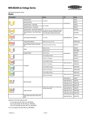
  • 1. Self-contained photoelectric sensors Models Sensing Mode Range LED Model OPPOSED Opposed Emitter 3 m (10 ft) Infrared 880 nm SM31E Opposed Receiver SM31R Opposed Emitter - Long Range 30 m (100 ft) SM31EL Opposed Receiver - Long Range SM31RL OPPOSED Opposed Emitter - Clear Plastic Detection 0 to 300 mm (0 to 12 in) Actual range varies, depending on the light transmission proper- ties of the plastic material being sensed. Visible Red 650 nm SM31EPD Opposed Receiver - Clear Plastic Detec- tion SM31RPD RETRO Non-Polarized Retroreflective 5 m (15 ft) SM312LV P POLAR RETRO Polarized Retroreflective 55 mm to 2 m (2 in to 7 ft) SM312LVAG Extended-Range Polarized Retroreflec- tive 10 mm to 3 m (0.4 in to 10 ft) SM312LP DIFFUSE Diffuse 380 mm (15 in) Infrared 880 nm SM312D 300 mm (12 in) SM312DBZ Divergent Diffuse 130 mm (5 in) SM312W CONVERGENT Convergent 16 mm (0.65 in) Focus SM312C 43 mm (1.7 in) Focus SM312C2 CONVERGENT 16 mm (0.65 in) Focus Visible Red 650 nm SM312CV 43 mm (1.7 in) Focus SM312CV2 CONVERGENT 16 mm (0.65 in) Focus Visible Blue 475 nm SM312CVB 49 mm (1.9 in) Focus SM312CV2B CONVERGENT 16 mm (0.65 in) Focus Visible Green 525 nm SM312CVG 49 mm (1.9 in) Focus SM312CV2G GLASS FIBER Glass Fiber Optic Range varies, depending on sensing mode and fiber optics used. Infrared 880 nm SM312F Visible Red 650 nm SM312FV Visible Blue 475 nm SM312FVB Visible Green 525 nm SM312FVG PLASTIC FIBER Plastic Fiber Optic Visible Red 650 nm SM312FP Visible Blue 475 nm SM312FPB Visible Green 525 nm SM312FPG Special High-Power Option Plastic Fiber Optic Visible Red 650 nm SM312FPH Standard 2 m (6.5') cable models are listed. • 9 m (30') cable: add suffix “W/30” (e.g., SM31EW/30). • 4-pin Euro QD models: add suffix “QD” (e.g., SM31EQD). • 150 mm (6") QD Pigtail: add suffix “QDP” (e.g., SM31EQDP). For a 0.3 ms response: add suffix “MHS” (eg., SM31EMHS). MINI-BEAM dc-Voltage Series P/N 69943 rev. C 6/19/2012
  • 2. Dimensions Models with suffix E, EL, EPD, R, RL, RPD, LV, LVAG, LP, D, C, C2, CV, CV2, CVG, CV2G, CVB, and CV2B Models with suffix DBZ and W 3.2 mm (0.13”) 12.2 mm (0.48”) 3 mm dia Clearance (2) M18 × 1 × 15 mm Thread (Mounting nut supplied) 27.4 mm (1.08”) 53.3 mm (2.10”) 19.1 mm (0.75”) Mounting peg (6.3 mm dia × 2.5 mm) 2 m (6.5’) Cable 30.7 mm (1.21”) 24.1 mm (0.95”) 3 mm dia Clearance (2) Bezel 18.0 mm (0.71”) 13.2 mm (0.52”) 39.1 mm (1.54”) Models with suffix F, FV, FVB, and FVG Models with suffix FP, FPB, FPG, and FPH M18 x 1 x 19 mm Thread (Mounting Nut Supplied) 57.5 mm (2.27") 31.2 mm (1.23") Fiber Optic Fitting 3.2 mm (0.13”) 12.2 mm (0.48”) 3 mm dia clearance (2) Fiber Optic Fitting 22.3 mm (0.88”) 16.2 mm (0.64”) 42.1 mm (1.66”) 19.1 mm (0.75”) Mounting Peg (6.3 mm dia × 2.5 mm) 2 m (6.5’) Cable 30.7 mm (1.21”) 24.1 mm (0.95”) QD Models Sensor Features 20.0 mm (0.79”) 12 mm Thread Quick-disconnect Gain (Sensitivity) Adjustment Screw Alignment Indicator Device (AID)* Light/Dark Operate Select Switch Clockwise: Light Operate (outputs conduct when sensing light is received). Counterclockwise: Dark Operate (outputs conduct when sensing light is not received). *U.S. Patent no. 4356393 MINI-BEAM dc-Voltage Series 2 www.bannerengineering.com - tel: 763-544-3164 P/N 69943 rev. C
  • 3. Wiring Diagrams Emitters with Attached Cable All Other Models with Attached Cable bn bu + – 10-30V dc bn wh bu + – bk Load Load 10-30V dc Emitters with Quick Disconnect (4-pin Euro-Style) All Other Models with Quick Disconnect (4-pin Euro-Style) bn wh bu + – bk 10-30V dc bn wh bu + – bk Load Load 10-30V dc The output type for all models is Bipolar NPN/PNP; load 150 mA max., each output. Sensor Mounting and Alignment MINI-BEAM sensors perform most reliably if they are properly aligned and securely mounted. For maximum mechanical stability, mount MINI-BEAM sensors through 18 mm diameter holes by their threaded barrel (where available), or use a mounting bracket. A complete selection of mounting brackets is available. Visit www.bannerengineering.com or contact the factory for information on mounting options. Begin with line-of-sight positioning of the MINI-BEAM sensor to its emitter (opposed-mode sensing) or to its target (all other sensing modes). When using a retroreflective sensor, the target is the retroreflector (“retro target”). For diffuse or convergent sensing modes, the target is the object to be detected. Apply power to the sensor (and to the emitter, if using the opposed mode). Advance the 15-turn Gain control to maximum (clockwise end of rotation) using a small flat-blade screwdriver. The Gain control is clutched at both ends to avoid damage and will “free-wheel” when either endpoint is reached. If the MINI-BEAM sensor is receiving its light signal, the red LED Alignment indicator will be ON and flashing at a rate proportional to the signal strength (faster = more signal). Move the sensor (or retro target, if applicable) up-down-right-left (including angular rotation) to find the center of the movement zone within which the LED indicator remains ON. Reducing the Gain setting reduces the size of the movement zone for more precise alignment. Repeat the alignment motions after each Gain reduction. When optimum alignment is achieved, mount sensor(s) (and the retro target, if applicable) solidly in that position. Increase the Gain to maximum. Test the sensor by placing the object to be detected in the sensing position, then removing it. The Alignment indicator LED should come ON when the sensing beam is established (Light condition) or be ON when the beam is broken (Dark condition). If the Alignment indicator LED stays ON for both sensing conditions, consider the follow- ing tips for each sensing mode. Opposed Mode Alignment Object Emitter Receiver “Flooding” occurs when a portion of the sensing beam passes around the object to be sensed. “Burn-through” occurs when a portion of the emitter’s light energy pass- es through a thin or translucent object, and is sensed by the receiver. To correct either problem, do one or more of the following to reduce the light ener- gy: • Reduce the Gain adjustment on the receiver. • Add an aperture to one or both lenses. (MINI-BEAM apertures, available from Banner, fit neatly inside the lens assembly.) • Intentionally misalign the emitter and receiver. Note: • Light condition: sensor output is ON when there is no object in beam • Dark condition: sensor output is ON when there is an object in beam MINI-BEAM dc-Voltage Series P/N 69943 rev. C www.bannerengineering.com - tel: 763-544-3164 3
  • 4. Diffuse Mode Alignment Object If the Alignment LED does not go OFF when the object is removed from the beam, the sensor is probably detecting light reflected from some background object. To remedy this problem: • Reduce the reflectivity of the background by painting the surface(s) flat-black, scuffing any shiny surface, or drilling a large hole, directly opposite the diffuse sensor. • Move the sensor closer to the object to be detected and reduce the Gain ad- justment. Rule of thumb for diffuse sensing: The distance to the nearest back- ground object should be at least three times the sensing distance. Note: • Light condition: sensor output is ON when there is no object in beam • Dark condition: sensor output is ON when there is an object in beam Retroreflective Mode Alignment Retro Target A highly reflective object may reflect enough light back to a retroreflective sensor to allow that object to slip through the beam, without being detected. This problem is called “proxing,” and the following methods may be used to correct it: • Position the sensor and retro target so the beam will not strike a shiny surface perpendicular to the sensor lens. • Reduce the Gain adjustment. • Add a polarizing filter (for model SM312LV). Note: • Light condition: sensor output is ON when there is no object in beam • Dark condition: sensor output is ON when there is an object in beam Convergent Mode Alignment Object Low Reflectivity Background The sensing energy of a convergent mode sensor is concentrated at the specified focus point. Convergent mode sensors are less sensitive to background reflections, compared with diffuse mode sensors. However, if background reflections are a problem: • Skew the sensor position at a 10° to 25° angle to eliminate direct reflections from shiny background surfaces. • Reduce the reflectivity of the background by painting the surface(s) flat-black, scuffing any shiny surface, or drilling a large hole, directly opposite the sensor. • Reduce the Gain adjustment. Note: • Light condition: sensor output is ON when there is no object in beam • Dark condition: sensor output is ON when there is an object in beam MINI-BEAM dc-Voltage Series 4 www.bannerengineering.com - tel: 763-544-3164 P/N 69943 rev. C
  • 5. Glass Fiber Installation O-ring Retaining Clip 1. Install the O-ring (supplied with the fiber) on each fiber end, as shown in the drawing. 2. While pressing the fiber ends firmly into the ports on the sensor front, slide the U-shaped retaining clip (supplied with the sensor) into the slot in the sensor’s barrel, until it snaps into place. Plastic Fiber Installation Trimmed fiber control ends Plastic fiber emitter port Plastic fiber receiver port Gripper Unlock Lock Adapters for 0.25- and 0.5-mm fibers Sensor Face 1. With supplied fiber cutter, make a clean cut at control ends of fibers. 2. Unlock the fiber gripper as shown below. Apply appropriate fiber adaptors prior to fiber insertion, if needed. 3. Gently insert the prepared fiber ends into the ports, as far as they will go. 4. Slide the fiber gripper back to lock, as shown below. MINI-BEAM dc-Voltage Series P/N 69943 rev. C www.bannerengineering.com - tel: 763-544-3164 5
  • 6. Specifications Supply Voltage and Current 10 to 30V dc (10% maximum ripple) at less than 25 mA (exclusive of load) Supply Protection Circuitry Protected against reverse polarity and transient voltages Output Configuration Bipolar: One current sourcing (PNP) and one current sinking (NPN) open collector transistor Output Rating 150 mA maximum each output at 25° C, derated to 100 mA at 70° C (derate ≈ 1 mA per ° C) OFF State Leakage Current: less than 1 microamp Output Saturation Voltage (PNP Output): less than 1 volt at 10 mA, less than 2 volts at 150 mA Output Saturation Voltage (NPN Output): less than 200 millivolts at 10 mA, less than 1 volt at 150 mA Output Protection Circuitry Protected against false pulse on power-up and continuous overload or short-circuit of outputs Output Response Time Sensors will respond to either a “light” or “dark” signal of 1 millisecond or longer duration, 500 Hz maximum. Modification for 0.3 millisecond re- sponse is available (MHS-suffix models; these models also feature re- duced sensitivity range and reduced repeatability.) NOTE: Outputs are non-conducting during 100 millisecond delay on power-up. Repeatability Opposed: 0.14 milliseconds Non-Polarized and Polarized Retro, Diffuse, Convergent, Glass Fiber Optic, and Plastic Fiber Optic: 0.3 milliseconds Response time and repeatability specifications are independent of signal strength. Adjustments Light/Dark Operate Select switch 15-turn slotted brass screw Gain (sensitivity) adjustment potentiometer (clutched at both ends of travel) Located on the rear panel, protected by a gasketed, clear acrylic cover. Indicators Patented alignment Indicator Device system (AID™, US patent #4356393) lights a rear-panel-mounted LED indicator when the sensor sees light. Its pulse rate is proportional to the light signal strength (the stronger the signal, the faster the pulse rate). Construction Reinforced thermoplastic polyester housing, totally encapsulated, o-ring sealing, acrylic lenses, stainless steel screws Environmental Rating Meets NEMA standards 1, 2, 3, 3S, 4, 4X, 6, 12, and 13; IEC IP67. Connections PVC-jacketed 4-conductor 2 m (6.5') or 9 m (30') cables, or 4-pin Euro- style QD fitting; QD cables available separately Operating Conditions Temperature: –20° to +70°C (–4° to +158°F) Maximum relative humidity: 90% at 50°C (non-condensing) Application Note The NPN (current sinking) output of dc MINI-BEAM sensors is directly compatible as an input to Banner logic modules, including all non-ampli- fied MAXI-AMP and MICRO-AMP modules. MINI-BEAMs are TTL com- patible. Certifications WARNING: Not To Be Used for Personnel Protection Never use this product as a sensing device for personnel protection. Doing so could lead to serious injury or death. This product does NOT include the self-checking redundant circuitry necessary to allow its use in personnel safety applications. A sensor failure or malfunction can cause either an energized or de-energized sensor output condition. Banner Engineering Corp Limited Warranty Banner Engineering Corp. warrants its products to be free from defects in material and workmanship for one year following the date of shipment. Banner Engineering Corp. will repair or replace, free of charge, any product of its manufacture which, at the time it is returned to the factory, is found to have been defective during the warranty period. This warranty does not cover damage or liability for misuse, abuse, or the improper application or installation of the Banner product. THIS LIMITED WARRANTY IS EXCLUSIVE AND IN LIEU OF ALL OTHER WARRANTIES WHETHER EXPRESS OR IMPLIED (INCLUDING, WITHOUT LIMITATION, ANY WARRANTY OF MERCHANTABILITY OR FITNESS FOR A PARTICULAR PURPOSE), AND WHETHER ARISING UNDER COURSE OF PERFORMANCE, COURSE OF DEALING OR TRADE USAGE. This Warranty is exclusive and limited to repair or, at the discretion of Banner Engineering Corp., replacement. IN NO EVENT SHALL BANNER ENGINEERING CORP. BE LIABLE TO BUYER OR ANY OTHER PERSON OR ENTITY FOR ANY EXTRA COSTS, EXPENSES, LOSSES, LOSS OF PROFITS, OR ANY INCIDENTAL, CONSE- QUENTIAL OR SPECIAL DAMAGES RESULTING FROM ANY PRODUCT DEFECT OR FROM THE USE OR INABILITY TO USE THE PRODUCT, WHETHER ARIS- ING IN CONTRACT OR WARRANTY, STATUTE, TORT, STRICT LIABILITY, NEGLIGENCE, OR OTHERWISE. Banner Engineering Corp. reserves the right to change, modify or improve the design of the product without assuming any obligations or liabilities relating to any product previously manufactured by Banner Engineering Corp. MINI-BEAM dc-Voltage Series