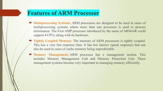
An Arm processor is a type of central processing unit (CPU) based on the RISC (Reduced Instruction Set Computing) architecture. ARM stands for Advanced RISC Machine. These processors are known for their energy efficiency and are widely used in mobile devices, embedded systems, and increasingly in servers and desktops.
Here's a more detailed explanation:
Key Characteristics:
RISC Architecture:
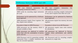
Unlike the more complex instruction sets found in some other processors (like x86), ARM processors use a streamlined set of instructions, which contributes to their efficiency.
Energy Efficiency:
ARM processors are designed to consume less power, making them ideal for battery-powered devices like smartphones, tablets, and wearables.
Licensing Model:
ARM Holdings, the company that designs the architecture, licenses it to other companies who then design and manufacture the actual processors.
Wide Range of Applications:
ARM processors are found in a vast array of devices, including smartphones, tablets, laptops, embedded systems, and even some supercomputers.
Examples of ARM-based devices:
Smartphones and Tablets:
Most smartphones and tablets, including those from Apple, Samsung, and Qualcomm, utilize ARM processors.
Laptops and Desktops:
Apple's M1, M2, and M3 chips used in MacBooks and iMacs are based on the ARM architecture.
Embedded Systems:
ARM processors are commonly found in a wide range of embedded systems, such as those in cars, industrial equipment, and consumer electronics.
Servers:
ARM processors are increasingly being used in servers, particularly in cloud computing environments, due to their energy efficiency and scalability.
In essence, ARM processors are a popular choice for devices where power consumption and size are critical factors, while still offering sufficient performance for demanding tasks.
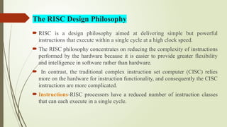
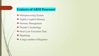
The ARM core uses RISC architecture.
The RISC philosophy is implemented with four major design rules:
1. Instructions – RISC processors have a reduced number of instruction classes. These
classes provide simple operations that can each execute in a single cycle. The compiler or
programmer synthesizes complicated operations (a divide operation) by combining
several simple instructions. Each instruction is a fixed length to allow the pipeline to
fetch future instructions before decoding the current instruction. In contrast, in CISC
processors the instructions are often of variable size and take many cycles to execute.
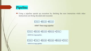
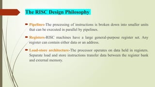
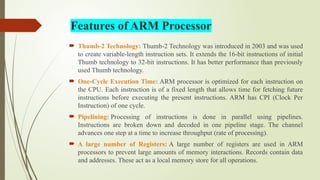
2. Pipelines —The processing of instructions is broken down into smaller units that can be
executed in parallel by pipelines. Ideally the pipeline advances by one step on each cycle
for maximum throughput. There is no need for an instruction to be executed by a mini
program called microcode as on CISC processors.
3. Registers—RISC machines have a large general-purpose register set. Any register can
contain either data or an address. In contrast, CISC processors have dedicated registers
for specific purposes.
4. Load-store archi

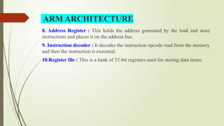
![ The ARM architecture processor is an advanced reduced instruction set
computing [RISC] machine and it's a 32 bit RISC microcontroller.
The ARM cortex is a complicated microcontroller within the ARM family
that has ARMv7 design.
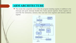
The ARM Architecture consists of following: a) Arithmetic Logic Unit b)
Booth multiplier c) Barrel shifter d) Control unit e) Register file
The ARM processor conjointly has other components like the Program
status register, which contains the processor flags (Z, S, V and C).
ARM ARCHITECTURE](https://image.slidesharecdn.com/armprocessor-250707070139-723a59df/85/ARM-Processor-pptxARM-means-Advanced-RISC-Machines-17-320.jpg)