This manual provides instructions for operating a Humminbird GPS chartplotter. It discusses how sonar and GPS/cartography work and the various views and functions available on the display. Key sections include instructions for navigation features like waypoints, routes, and tracks as well as explanations of menu options and basic unit operation.


![Table of Contents
Navigation X-PressTM Menu (Navigation views only) 40
Waypoint [Name] (only with an active cursor on a waypoint) . . . . . . . . . . . . . . . . . . . . . . . . . . . . 41
Cursor To Waypoint (Chart or Combo view only). . . . . . . . . . . . . . . . . . . . . . . . . . . . . . . . . . . . . . . 42
Save Current Track . . . . . . . . . . . . . . . . . . . . . . . . . . . . . . . . . . . . . . . . . . . . . . . . . . . . . . . . . . . . . . . . 42
Clear Current Track . . . . . . . . . . . . . . . . . . . . . . . . . . . . . . . . . . . . . . . . . . . . . . . . . . . . . . . . . . . . . . . . 43
Save Current Route (only when navigating). . . . . . . . . . . . . . . . . . . . . . . . . . . . . . . . . . . . . . . . . . . 43
Skip Next Waypoint (only when navigating) . . . . . . . . . . . . . . . . . . . . . . . . . . . . . . . . . . . . . . . . . . 43
Cancel Navigation (only when navigating) . . . . . . . . . . . . . . . . . . . . . . . . . . . . . . . . . . . . . . . . . . . 44
Remove Target (only if Target is Active) . . . . . . . . . . . . . . . . . . . . . . . . . . . . . . . . . . . . . . . . . . . . . . . 44
Remove Grid (only if Grid is Active) . . . . . . . . . . . . . . . . . . . . . . . . . . . . . . . . . . . . . . . . . . . . . . . . . . . 45
Sonar Window (Combo view only) . . . . . . . . . . . . . . . . . . . . . . . . . . . . . . . . . . . . . . . . . . . . . . . . . . . 45
Waypoint [Name] (Most recently-created waypoint) . . . . . . . . . . . . . . . . . . . . . . . . . . . . . . . . . . . 46
Sonar Menu Tab 47
Fish ID+TM . . . . . . . . . . . . . . . . . . . . . . . . . . . . . . . . . . . . . . . . . . . . . . . . . . . . . . . . . . . . . . . . . . . . . . . . . 48
Fish ID Sensitivity . . . . . . . . . . . . . . . . . . . . . . . . . . . . . . . . . . . . . . . . . . . . . . . . . . . . . . . . . . . . . . . . . 49
Real Time Sonar (RTS®) Window . . . . . . . . . . . . . . . . . . . . . . . . . . . . . . . . . . . . . . . . . . . . . . . . . . 49
Zoom Width . . . . . . . . . . . . . . . . . . . . . . . . . . . . . . . . . . . . . . . . . . . . . . . . . . . . . . . . . . . . . . . . . . . . . . 50
Depth Lines (Advanced) . . . . . . . . . . . . . . . . . . . . . . . . . . . . . . . . . . . . . . . . . . . . . . . . . . . . . . . . . . . . 50
Surface Clutter (Advanced) . . . . . . . . . . . . . . . . . . . . . . . . . . . . . . . . . . . . . . . . . . . . . . . . . . . . . . . . . . 51
Noise Filter (Advanced) . . . . . . . . . . . . . . . . . . . . . . . . . . . . . . . . . . . . . . . . . . . . . . . . . . . . . . . . . . . . . 52
Max Depth (Advanced) . . . . . . . . . . . . . . . . . . . . . . . . . . . . . . . . . . . . . . . . . . . . . . . . . . . . . . . . . . . . . 52
Water Type (Advanced) . . . . . . . . . . . . . . . . . . . . . . . . . . . . . . . . . . . . . . . . . . . . . . . . . . . . . . . . . . . . . 53
Navigation Menu Tab 54
Current Track. . . . . . . . . . . . . . . . . . . . . . . . . . . . . . . . . . . . . . . . . . . . . . . . . . . . . . . . . . . . . . . . . . . . . . 55
Saved Tracks . . . . . . . . . . . . . . . . . . . . . . . . . . . . . . . . . . . . . . . . . . . . . . . . . . . . . . . . . . . . . . . . . . . . . . 56
Waypoints . . . . . . . . . . . . . . . . . . . . . . . . . . . . . . . . . . . . . . . . . . . . . . . . . . . . . . . . . . . . . . . . . . . . . . . . 57
Routes . . . . . . . . . . . . . . . . . . . . . . . . . . . . . . . . . . . . . . . . . . . . . . . . . . . . . . . . . . . . . . . . . . . . . . . . . . . . 58
Chart Orientation . . . . . . . . . . . . . . . . . . . . . . . . . . . . . . . . . . . . . . . . . . . . . . . . . . . . . . . . . . . . . . . . . 59
North Reference . . . . . . . . . . . . . . . . . . . . . . . . . . . . . . . . . . . . . . . . . . . . . . . . . . . . . . . . . . . . . . . . . . 59
Grid Rotation . . . . . . . . . . . . . . . . . . . . . . . . . . . . . . . . . . . . . . . . . . . . . . . . . . . . . . . . . . . . . . . . . . . . . 59
Trackpoint Interval . . . . . . . . . . . . . . . . . . . . . . . . . . . . . . . . . . . . . . . . . . . . . . . . . . . . . . . . . . . . . . . . 60
iv](https://image.slidesharecdn.com/161-090720131937-phpapp02/85/161-5-320.jpg)


![Upper Range
(Advanced: Sonar, Split Sonar, Big Digits
and Circular Flasher views only)
Upper Range sets the shallowest depth range that will be displayed on the Sonar, Split
Sonar, Big Digits and Circular Flasher Views. The Upper Range menu choice is available
when User Mode is set to Advanced (see Setup Menu Tab: User Mode) and can only be
accessed from the Sonar, Big Digits and Circular Flasher Views. Upper Range is often
used with Lower Range.
For example, if you are only interested in the area between 20 and 50 feet
deep, you should set the Upper Depth Range to 20 and the Lower Depth
Range to 50. The Sonar View will then show the 30 foot area between 20
and 50, and will not show the surface or the bottom (assuming the
bottom is deeper than 50 feet), and will show greater detail for that area
between 20 and 50 feet.
NOTE: A minimum distance of 10 feet will be maintained between the Upper and Lower
Range regardless of the manual settings entered.
To adjust the Upper Range:
1. Make sure you are in Advanced Mode, then highlight Upper Range on the
Sonar X-PressTM menu.
2. Use the LEFT or RIGHT 4-WAY Cursor Control keys to increase or
decrease the Upper Range setting. (0 to 590 feet or 0 to 237 meters
[International Models only], Default = 0)
35](https://image.slidesharecdn.com/161-090720131937-phpapp02/85/161-42-320.jpg)
![Lower Range
Lower Range sets the deepest depth range that will be
displayed. Automatic is the default setting. When in automatic mode, the lower range
will be adjusted by the unit to follow the bottom. Selecting a specific setting locks the
depth range into Manual mode. Use both Upper and Lower Range together to view a
specific depth range manually when looking for fish or bottom structure. M will be
displayed in the lower right corner of the screen when you start manually adjusting the
Lower Range to indicate that you are in Manual mode.
For example, if you are fishing in 60 feet of water but are only interested
in the first 30 feet (surface to a depth of 30 feet) you should set the Lower
Depth Range limit to 30. The display will show the 0 to 30 foot range,
allowing you to see a more detailed view than you would see if the
display went all the way to the bottom.
NOTE: A minimum distance of 10 feet will be maintained between the Upper and Lower
Range regardless of the manual settings entered.
To adjust the Lower Range:
1. Highlight Lower Range on the Sonar X-PressTM menu.
2. Use the LEFT or RIGHT 4-WAY Cursor Control keys to increase or decrease
the Lower Range setting. (AUTO, 10 to 600 feet, 3 to 240 meters
[International Models only], Default = AUTO)
36](https://image.slidesharecdn.com/161-090720131937-phpapp02/85/161-43-320.jpg)

![Bottom Range
(Sonar Zoom view only when Bottom Lock is On)
Bottom Range allows you to control how much of the water column, measured up
from the bottom, is shown in the Sonar Zoom View. Choose a small value to see low-
lying bottom structure or details of the bottom return. Choose a larger value to see
large structure in deeper water. It is possible to set the Bottom Range to be greater
than the depth. In this case, you may see surface clutter in a wavy band that mirrors
changes in the depth.
To adjust the Bottom Range:
1. In the Sonar Zoom View, highlight Bottom Range on the Sonar X-PressTM menu.
2. Use the LEFT or RIGHT 4-WAY Cursor Control keys to change the Bottom
Range setting. (10 - 60 feet or 3-20 meters [International Models only],
Default = 15 feet)
Bottom Lock
(Sonar Zoom view only)
Bottom Lock changes the mode of the Zoomed view in the Sonar Zoom View. Bottom
Lock continuously graphs the bottom at a constant point on the display regardless of
changes in depth. This "flattens" out the bottom contour, but is effective at showing fish
on or near the bottom.
To turn on Bottom Lock:
1. In the Sonar Zoom View, highlight Bottom Lock on the Sonar X-PressTM Menu.
2. Use the LEFT or RIGHT 4-WAY Cursor Control keys to change the Bottom Lock
setting to on. (Off, On, Default = Off)
38](https://image.slidesharecdn.com/161-090720131937-phpapp02/85/161-45-320.jpg)


![Waypoint [Name]
(Only with an active cursor on a waypoint)
Waypoint [Name] allows you to view the Waypoints submenu for the waypoint under
your cursor.
To view the Waypoint [Name] Submenu:
1. Move the cursor onto an existing waypoint and press the MENU key once, or use
Cursor to Waypoint to select a waypoint from a list of saved waypoints.
2. Highlight Waypoint[Name] on the Navigation X-PressTM menu.
3. Use the RIGHT 4-Way Cursor Control key to view the Waypoints submenu, which
contains the following menu choices:
Waypoints Submenu
The Waypoint Submenu contains the following menu choices:
Edit allows you to edit the Name, Position (Latitude and Longitude) and select the Icon
that will be used to represent the waypoint in the Chart and Combo Views.
Delete allows you to delete a waypoint from the list of saved waypoints.
Target allows you to apply a target to a waypoint selected from the list of waypoints.
Grid allows you to apply a trolling grid to a waypoint selected from the list of waypoints.
41](https://image.slidesharecdn.com/161-090720131937-phpapp02/85/161-48-320.jpg)


![Waypoint [Name]
(Most recently-created waypoint)
Waypoint [Name] allows you to view the waypoints submenu for the most recently
created waypoint.
NOTE: You must have pressed the MARK key at least once since you last powered up the
fishfinder for this menu choice to appear.
To view the Waypoint [Name] Submenu:
1. Move the cursor to the desired position and press the MARK key once to save a
waypoint.
2. Highlight Waypoint[Name] on the Navigation X-PressTM menu.
3. Use the RIGHT 4-Way Cursor Control key to view the Waypoints submenu.
Waypoint [Name] Submenu
The Waypoint Submenu contains the following menu choices:
Edit allows you to edit the Name, Position (Latitude and Longitude) and select the Icon
that will be used to represent the waypoint in the Chart and Combo Views.
Delete allows you to delete a waypoint from the list of saved waypoints.
Go To allows you to select a waypoint and start navigation toward that waypoint, or add
that waypoint to the end of the current route.
Target allows you to apply a target to a waypoint selected from the list of waypoints.
Grid allows you to apply a trolling grid to a waypoint selected from the list of waypoints.
46](https://image.slidesharecdn.com/161-090720131937-phpapp02/85/161-53-320.jpg)


![Noise Filter
(Advanced)
Noise Filter adjusts the sonar Noise Filter to limit interference on the display
from sources such as your boat engine, turbulence, or other sonar devices.
The Noise Filter menu choice is available when User Mode is set to Advanced
(see Setup Menu Tab: User Mode).
NOTE: The Off setting removes all filtering; Low, Medium and High settings add progressive
filtering of the sonar returns. In some deep water situations, the High setting may actually
hinder your unit’s ability to find the bottom.
To change the Noise Filter setting:
1. Make sure you are in Advanced User Mode, then highlight Noise Filter on the
Sonar main menu.
2. Use the LEFT or RIGHT 4-WAY Cursor Control keys to change the Noise Filter
setting. (Off, Low, Medium, High1, High2, High3, Default = Low)
Max Depth
(Advanced)
Max Depth adjusts the maximum depth of operation. The performance of your 100
SeriesTM Fishing System can be tuned to the maximum depth you will be fishing in by
setting the Max Depth. When a maximum depth is set, your 100 SeriesTM Fishing System
will not attempt to acquire sonar data below that depth, thus increasing overall
performance. When Max Depth is set to Auto, the 100 SeriesTM Fishing System will acquire
bottom readings as needed (within the capacity of the unit). If the bottom is deeper than
the Max Depth setting, the digital depth readout will flash, indicating that the 100
SeriesTM Fishing System cannot locate the bottom. The Max Depth menu choice is
available when User Mode is set to Advanced (see Setup Menu Tab: User Mode).
To change the Max Depth setting:
1. Make sure you are in Advanced User Mode, then highlight Max Depth on the
Sonar main menu.
2. Use the LEFT or RIGHT 4-WAY Cursor Control keys to change the Max Depth
setting. (AUTO, 10 to 600 feet, 3 to 240 meters [International Models only],
Default = AUTO)
52](https://image.slidesharecdn.com/161-090720131937-phpapp02/85/161-59-320.jpg)


![Trackpoint Interval
Trackpoint Interval allows you to select the time
period between trackpoints. The current track can only contain up to 20,000
trackpoints, so longer time periods cause the track to extend back further in time,
but will be less detailed.
NOTE: Trackpoint Interval works in conjunction with Track Min Distance. Both conditions
must be met before a trackpoint is added to the current track.
To change the Trackpoint Interval setting:
1. Highlight Trackpoint Interval on the Navigation main menu.
2. Use the LEFT or RIGHT 4-WAY Cursor Control keys to change the Trackpoint
Interval setting. (1 second, 5 seconds, 10 seconds, 15 seconds, 30 seconds or 60
seconds, Default = 15 seconds)
NOTE: During slow travel or drift, setting both Trackpoint Interval and Track Min Distance to
small values will allow you to increase the track resolution.
Track Min Distance
(Advanced)
Track Min Distance allows you to set a minimum distance of travel before a trackpoint
is added to the track. The Track Min Distance menu choice is only available when User
Mode is set to Advanced (see Setup Menu Tab: User Mode).
NOTE: Track Min Distance works in conjunction with Trackpoint Interval. Both conditions
must be met before a trackpoint is added to the current track.
To change the Track Minimum Distance setting:
1. Make sure you are in Advanced User Mode, then highlight Track Min Distance
on the Navigation main menu.
2. Use the LEFT or RIGHT 4-WAY Cursor Control keys to change the Track Min
Distance setting. (1 to 300 feet or 1 to 100 meters [International Units only],
Default = 16 ft, 5 m)
NOTE: During slow travel or drift, setting both Trackpoint Interval and Track Min Distance to
small values will allow you to increase the track resolution.
60](https://image.slidesharecdn.com/161-090720131937-phpapp02/85/161-67-320.jpg)


![Depth Alarm
Depth Alarm sounds when the depth becomes equal to
or less than the menu setting.
To change the Depth Alarm setting:
1. Highlight Depth Alarm on the Alarms main menu.
2. Use the LEFT or RIGHT 4-WAY Cursor Control keys to change the Depth Alarm
setting. (OFF, 1 to 100 feet, or 0.5 to 30 meters [International Models only],
Default = OFF)
Fish ID Alarm
Fish ID Alarm sounds when the Fishing System detects
fish that correspond to the alarm setting. Fish ID Alarm will only sound if Fish ID+TM is on.
For example, if you've set the Fish ID Alarm to sound for Large fish only,
the Fish ID alarm will sound when a large-sized fish is detected.
To change the Fish ID Alarm setting:
1. Highlight Fish ID Alarm on the Alarms main menu.
2. Use the LEFT or RIGHT 4-WAY Cursor Control keys to change the Fish ID Alarm
setting. (Off, All, Large/Medium, Large, Default = Off)
Off
Large
Large/Medium
All
68](https://image.slidesharecdn.com/161-090720131937-phpapp02/85/161-75-320.jpg)
![Low Battery Alarm
Low Battery Alarm sounds when the input battery
voltage is equal to or less than the menu setting. The battery alarm will only sound
for the battery that is connected to the 100 SeriesTM Fishing System. The Low Battery
Alarm should be set to warn you when the battery voltage drops below the safety
margin that you have determined. For instance, if you are running a trolling motor
(battery operated), you would want to set the Low Battery Alarm to sound before
the battery voltage drops too low for it to be used to start your main, gasoline-
powered engine.
To change the Low Battery Alarm setting:
1. Highlight Low Battery Alarm on the Alarms main menu.
2. Use the LEFT or RIGHT 4-WAY Cursor Control keys to change the Low Battery
Alarm setting. (Off, 8.5V - 13.5V, Default = Off)
Temp Alarm
Temp Alarm sounds when the water temperature
detected by the 100 SeriesTM reaches the Temp Alarm setting, which is either set in
degrees Fahrenheit or Celsius [International Models only]. For example, if the Temp
Alarm is set to 58 degrees Fahrenheit, and the water temperature falls from 60 degrees
to 58 degrees, the Temp Alarm will sound. Similarly, if the water temperature rises from
56 degrees to 58 degrees, the Temp Alarm will also sound.
To change the Temp Alarm setting:
1. Highlight Temp Alarm on the Alarms main menu.
2. Use the LEFT or RIGHT 4-Way Cursor Control keys to change the Temp Alarm
setting. (Off, 33-120 [Fahrenheit], 0-50 [Celsius], Default = Off)
69](https://image.slidesharecdn.com/161-090720131937-phpapp02/85/161-76-320.jpg)
![Off Course Alarm
Off Course Alarm sounds when the boat has moved
too far off course based on the menu setting when navigating. Off Course Alarm
allows you to set how far the boat is allowed to move off course before the Off
Course Alarm will sound.
Off Course Limits
Arrival Alarm Circle
To change the Off Course Alarm setting:
1. Highlight Off Course Alarm on the Alarms main menu.
2. Use the LEFT or RIGHT 4-WAY Cursor Control keys to change the Off Course Alarm
setting. (Off, 25 to 3000 feet, 10 to 1000 meters [International Models only],
Default = 300 ft, 100 m)
Arrival Alarm
Arrival Alarm sounds when the boat has either
exceeded the distance to the destination waypoint, or has entered the Arrival Alarm
Circle, based on the menu setting when navigating. Arrival Alarm allows you to set how
close the boat must be to the destination waypoint before the Arrival Alarm will sound.
To change the Arrival Alarm setting:
1. Highlight Arrival Alarm on the Alarms main menu.
2. Use the LEFT or RIGHT 4-WAY Cursor Control keys to change the Arrival Alarm
setting. (Off, 25 to 3000 feet, 10 to 1000 meters [International Models only],
Default = 150 ft, 50 m)
70](https://image.slidesharecdn.com/161-090720131937-phpapp02/85/161-77-320.jpg)
![Drift Alarm
Drift Alarm sounds when the boat has exceeded the
distance from the boat’s anchored position, based on the menu setting. Drift Alarm
allows you to set the size of a perimeter around the boat’s anchored position; if the
anchored boat drifts outside of that perimeter, the Drift Alarm will sound.
Drift Alarm Circle
Drift Alarm Perimeter
To change the Drift Alarm setting:
1. Highlight Drift Alarm on the Alarms main menu.
2. Use the LEFT or RIGHT 4-WAY Cursor Control keys to change the Drift Alarm
setting. (Off, 25 to 3000 feet, 10 to 1000 meters [International Models only],
Default = Off)
Alarm Tone
Alarm Tone selects the pitch of the alarm sound. A brief
tone will be produced as you adjust the Alarm Tone so that you can select the tone that
you can hear best.
To change the Alarm Tone setting:
1. Highlight Alarm Tone on the Alarms main menu.
2. Use the LEFT or RIGHT 4-WAY Cursor Control keys to change the Alarm Tone
setting. (High, Medium, Low, Default = Medium)
71](https://image.slidesharecdn.com/161-090720131937-phpapp02/85/161-78-320.jpg)

![Units - Depth
Units - Depth selects the units of measure for all depth-
related readouts.
To change the Units - Depth setting:
1. Highlight Units - Depth on the Setup menu.
2. Use the LEFT or RIGHT 4-WAY Cursor Control keys to change the Units - Depth
setting. (Meters [International Models only], Feet, Fathoms; Default is Meters
for International models, and Feet for Domestic models)
Units - Temp
(International only)
Units - Temp selects the units of measure for all temperature-related readouts.
International Models only.
To change the Units - Temp setting:
1. Highlight Units - Temp on the Setup menu.
2. Use the LEFT or RIGHT 4-WAY Cursor Control keys to change the Units - Temp
setting. (Celsius, Fahrenheit; Default = Celsius)
Units - Distance
Units - Distance selects the units of measure for all
distance-related readouts, and will appear in the menu if a Temp/Speed Accessory is
connected and the paddlewheel has moved at least once, or if the GPS Receiver is
connected.
To change the Units - Distance setting:
1. Highlight Units - Distance on the Setup menu.
2. Use the LEFT or RIGHT 4-WAY Cursor Control keys to change the Units - Distance
setting. (Domestic Models: Statute Miles, Nautical Miles; Default = Statute
Miles; International Models: Meters/Kilometers, Meters/Nautical Miles,
Feet/Statute Miles, Feet/Nautical Miles; Default = Meters/Kilometers)
73](https://image.slidesharecdn.com/161-090720131937-phpapp02/85/161-80-320.jpg)
![Units - Speed
Units - Speed selects the units of measure for speed-related
readouts, and will appear in the menu if a Temp/Speed Accessory is connected and the
paddlewheel has moved at least once, or if the GPS Receiver is connected.
To change the Units - Speed setting:
1. Highlight Units - Speed on the Setup menu.
2. Use the LEFT or RIGHT 4-WAY Cursor Control keys to change the Units - Speed
setting. (kph [International Models only], mph, kts, Default = kph for
International models and mph for Domestic models)
User Mode
User Mode sets the menu system to either Normal or
Advanced. When set to Normal (default setting,) only the basic menu options are
shown. When set to Advanced, additional menu choices are available.
To change the User Mode setting:
1. Highlight User Mode on the Setup menu.
2. Use the LEFT or RIGHT 4-WAY Cursor Control keys to change the User Mode
setting. (Normal, Advanced, Default = Normal)
Language
(International only)
Language selects the display language for menus. International Models only.
To change the Language setting:
1. Highlight Language on the Setup menu.
2. Use the LEFT or RIGHT 4-WAY Cursor Control keys to change the Language
setting. (Default = English)
74](https://image.slidesharecdn.com/161-090720131937-phpapp02/85/161-81-320.jpg)

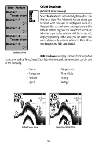
![To Select Readouts:
1. Make sure you are in Advanced User Mode, then highlight Select Readouts on
the Setup main menu.
2. Use the RIGHT 4-WAY Cursor Control key to initiate this procedure.
3. The Select Readouts submenu will appear, showing a list of all Readouts. Use
the UP or DOWN Cursor keys to select a particular Readout position, then
use the RIGHT or LEFT Cursor keys to change what will be displayed at that
position. (Course, Navigation, Position, Off, Speed, Temperature, Time+Date,
Triplog, Voltage)
Depth Offset
(Advanced)
Depth Offset will adjust the digital depth readout to indicate depth from the waterline
or boat's keel. Enter a positive vertical measurement from the transducer to the
waterline to read the depth from the waterline. Enter a negative vertical measurement
from the transducer to keel to read the depth from the keel. This menu choice is
available only when in Advanced User Mode (see Setup Menu Tab: User Mode.)
To change the Depth Offset setting:
1. Make sure you are in Advanced User Mode, then highlight Depth Offset on the
Setup menu.
2. Use the LEFT or RIGHT 4-WAY Cursor Control keys to change the Depth Offset setting.
(-10.0 to +10.0 feet or -3 to 3 meters [International Models only], Default = 0)
77](https://image.slidesharecdn.com/161-090720131937-phpapp02/85/161-84-320.jpg)

![Local Time Zone
(Advanced)
Local Time Zone selects your time zone in reference to the time reported by the
GPS receiver when Time+Date is selected as a Digital Readout on the Sonar View
(see Select Readouts). This menu choice is available only when in Advanced User
Mode (see Setup Menu Tab: User Mode).
To change the Local Time Zone:
1. Make sure you are in Advanced User Mode, then highlight Local Time Zone on
the Setup menu.
2. Use the LEFT or RIGHT 4-WAY Cursor Control keys to change the Local Time Zone
(Default = EST [UTC-5] - Eastern Standard Time).
Daylight Saving Time
(Advanced)
Daylight Saving Time adjusts the time display to account for local Daylight Saving Time
when Time+Date is selected as a Digital Readout on the Sonar View (see Select Readouts).
Selecting On adds one hour to the time display adjusted for your local time zone.
Selecting Off leaves the time display as adjusted for your local time zone. This menu
choice is available only when in Advanced User Mode (see Setup Menu Tab: User Mode).
To change the Daylight Saving Time setting:
1. Make sure you are in Advanced User Mode, then highlight Daylight Saving Time
on the Setup menu.
2. Use the LEFT or RIGHT 4-WAY Cursor Control keys to turn Daylight Saving Time
On or Off. (Off, On, Default = Off)
79](https://image.slidesharecdn.com/161-090720131937-phpapp02/85/161-86-320.jpg)