Download to read offline


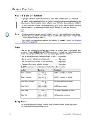
![Using thi s Manual
Congratulations on your purchase of the SmartFadeML control console. This manual will
hopefully get you up and running in no time. These are the manual conventions.
Instructions
Instructions are shown in a table with columns for Action, Console and Feedback.
Action Console Feedback
Activate Blackout mode BLACK
OUT
Button lights up. No output except from the
Independents.*
* There may be a comment like this with an asterisk.
Menu Directions
Many functions require menu navigation. For brevity’s sake, menu navigation is conveyed
in the following method:
Menu>Settings>Language>[English]
Each “>” indicates passage to a new menu sublevel, usually by pressing the MENU button.
Items [within brackets] are changed with the wheels or the SEL or MORE buttons.
Displays are shown like this
Text Conventions
• Buttons in tables are shown as images. Buttons in text are indicated with bold captial
letters followed by the word button. Like STACK button.
• References to other parts of the manual are indicated in italics. When viewing this
manual electronically, click on the reference to jump to that section of the manual.
Note: Notes are helpful hints and information that is supplemental to the main text.
CAUTION: A Caution statement indicates situations where there may be undefined or
unwanted consequences of an action, possible data loss or equipment problems.
Please E-mail comments about this manual to: TechComm@etcconnect.com
2 SmartFadeML v1.1 User Manual](https://image.slidesharecdn.com/smartfademlv11usermanualreva-100714162035-phpapp02/85/Smart-fademl-v1_1_user_manual_reva-8-320.jpg)

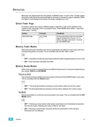
![Power-up and Shutdown Procedures
Unpack & Connect
You can get SmartFadeML up and running in no time.
• Unpack
• Connect power
• Connect DMX to dimmers and moving lights
• Power up
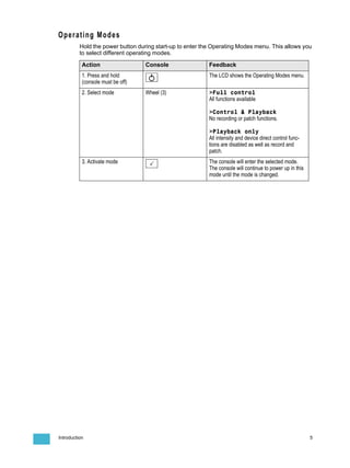
Power-up Procedure
SmartFade uses the power button for power-up and power-down. It is also used to access
the operating mode selection menu.
Action Console Feedback
Press and release The LCD shows the current software version.
[ETC SmartFade ML ]
[Version 1.0.0 2007]
The button LEDs will light up in the following
order: GREEN, RED, rest. After this all LEDs
light to the levels appropriate to the selected
mode of operation. *
* During the startup process, LEDs will fade to full brightness regardless of user settings.
Shutdown Procedure
Action Console Feedback
1. Press and release The LCD shows a message asking that you
confirm the shutdown command.
2a. Confirm Console is shut down.
2b. Cancel < Shutdown is cancelled and operation
resumed.
When you use the shutdown procedure, the SmartFade console will complete any pending
operations and save any system data as required to ensure error-free startup at the next
session. Disconnecting power from the console while it is shut down produces no ill effects.
4 SmartFadeML v1.1 User Manual](https://image.slidesharecdn.com/smartfademlv11usermanualreva-100714162035-phpapp02/85/Smart-fademl-v1_1_user_manual_reva-10-320.jpg)
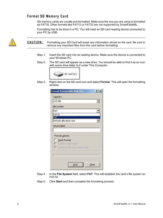
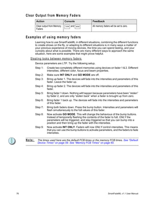
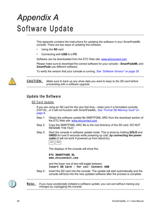
![Save & Load to Memory Card
SmartFadeML uses a standard SD Memory card as the primary external storage device.
Before you can use a new SD card make sure it is formatted correctly (FAT16). See
“Format SD Memory Card” on page 8.
The file format is Standard ASCII Light Cues. This format is compatible with other systems
that follow the same (and only) standard. Although there may be discrepancies between
systems, usually the main play data is compatible. For more information see www.usitt.org.
Save Show to card
This is done from the Save/Load Show menu
Menu>Save/Load Show>[Save as]
Shows may be given a two digit number with the wheel.
Showfiles saved in the ETC PC application SmartSoft can be given any valid DOS-style
name of 8 characters plus the suffix .ASC
Quick Save Show to card
This is done from the Save/Load Show menu
Menu>Save/Load Show>[Quick save]
If a file name has been used, it will save to this name, otherwise it will jump to the Save as
menu.
Load show from card
This is done from the Save/Load Show menu
Menu>Save/Load Show>[Load show]
Select the show with the wheel. The default show offered for loading will be the last show,
or the lowest numbered recording on the card.
6 SmartFadeML v1.1 User Manual](https://image.slidesharecdn.com/smartfademlv11usermanualreva-100714162035-phpapp02/85/Smart-fademl-v1_1_user_manual_reva-12-320.jpg)
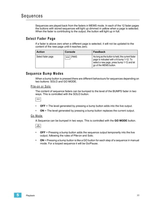
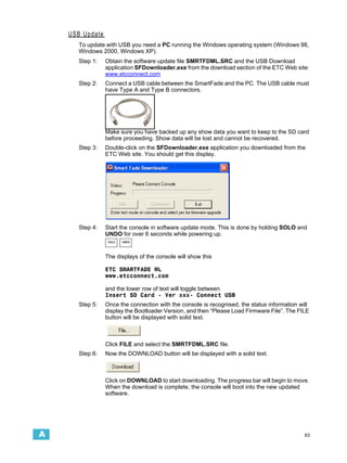
![Load patch from card
This is done from the Save/Load Show menu
Menu>Save/Load Show>[Save as]
Select the show with the wheel. The default show offered for loading a patch from will be
the lowest numbered recording on the card. The reason for this is that you may want to save
a dummy show with just a patch as show 001.
Introduction 7](https://image.slidesharecdn.com/smartfademlv11usermanualreva-100714162035-phpapp02/85/Smart-fademl-v1_1_user_manual_reva-13-320.jpg)
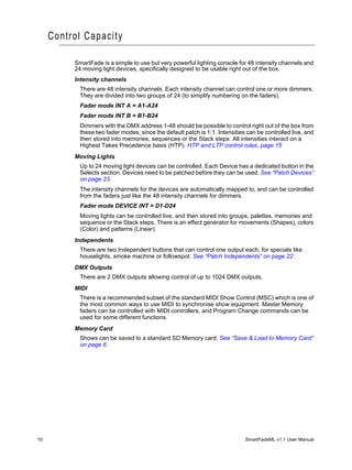
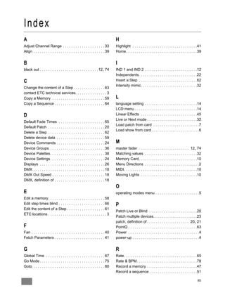
![DMX Output
DMX (Digital MultipleX) is a worldwide standard (or protocol) that your SmartFadeML uses
to communicate with lighting equipment. It is a digital protocol that basically defines a state
of “on”, “off” or a percentage of “on”. DMX can be used to control dimmers, moving lights,
fog machines, color scrollers, media servers or any number of other DMX devices.
DMX is restricted to a total of 512 (output) channels available in one DMX line (referred to
as a universe). Your SmartFadeML has two such universes, allowing control of up to 1024
outputs (2x512).
The DMX outputs are patched to console channels for intensities or devices in
SmartFadeML. There are 48 intensity channels, 24 device channels and 2 independent
channels. Each console channel can be patched to multiple outputs. The default is set 1:1.
INT A1-A24, , INT B1-B24, DEVICE INT D1-D24, IND 1, IND 2
A moving light device can have up to 48 different parameters, each parameter requiring one
of the 1024 outputs. This depends on the type of moving light, and is automatically set by
patching the appropriate template.
DMX Out Speed
In rare cases some DMX devices may have trouble reading DMX at the full standard speed
supplied by SmartFadeML. This is often seen as flicker in your lighting devices. You can
slow down the DMX out speed to try to alleviate such communications errors with other
manufacturer’s equipment. The default is set to “Max”.
Menu>Setup>DMX Out>[Max]..[Slow]..[Medium]..[Fast]
18 SmartFadeML v1.1 User Manual](https://image.slidesharecdn.com/smartfademlv11usermanualreva-100714162035-phpapp02/85/Smart-fademl-v1_1_user_manual_reva-24-320.jpg)
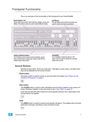
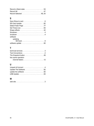
![Clear/Set Patch
Clear Intensity Patch
The intensity patch for INT A and INT B is cleared from the Patch Menu.
Menu>Patch>Patch Set/Clear>[Clear INT Patch]
Press OK to confirm.
Set Intensity Patch 1:1
The intensity patch for INT A and INT B is set 1:1 from the Patch Menu.
Menu>Patch>Patch Set/Clear>[Set INT Patch 1:1?]
Press OK to confirm.
Note: The Device Intensitiy channels can be used to patch 24 more conventional lights if no
Devices are being used. See “Patch by Channel” on page 21.
Clear Device Patch
Devices can be unpatced “all” or one by one in the Patch Menu.
Menu>Patch>Patch Set/Clear>[Clear Device]
Select All or 1-24 with wheel, and press OK to confirm.
2 Setup 19](https://image.slidesharecdn.com/smartfademlv11usermanualreva-100714162035-phpapp02/85/Smart-fademl-v1_1_user_manual_reva-25-320.jpg)
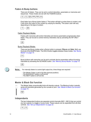
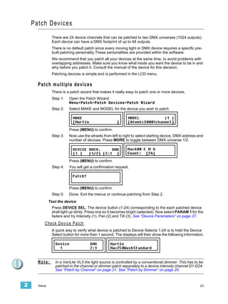
![Patch Dimmers (INT)
There are 48 intensity channels that can be patched to two DMX universes (1024 outputs).
They are divided into two groups of 24 - fader mode INT A and INT B.
The Default Patch
SmartFadeML defaults to a “1 to 1” patch mode in DMX universe 1 for dimmers.
INT A = DMX1-24
INT B = DMX 25-48
This is the simplest version of a patch and is the most common, as it is easy to remember
and provides immediate control with all of your available channels. It is also possible to
create a custom patch by assigning any DMX output(s) to any control channel. Setting the
patch is simple and is performed on the LCD menu.
Patch Live or Blind
Patching in Live will set the selected DMX output to full , and set all other dimmers to zero
so you can see what’s connected to that dimmer. Patching in Blind will not affect current
DMX values until changes in the patch override any active channels.
Note: A dimmer can only be patched to one control channel at a time. If you patch a dimmer
and then later patch the same dimmer to a different channel, the dimmer will be
automatically unpatched from its original channel and assigned to the new channel.
Patch by Dimmer
Patching by dimmer is probably the easiest way to patch a rig that is unknown to you. In
Live mode you can turn on each output one by one, select an intensity channel and patch it.
Step 1: Open the Patch:
Menu>Patch>[Patch by dimmer]
Step 2: Choose between Live and Blind mode using encoder wheel 3.
Press (MENU) to confirm.
Step 3: All patching is done in the left LCD.
Menu choice Console Feedback
DMX Wheel 1 Select a DMX output. If you are patching Live
it will be set to full instantly.
CH. Wheel 2 Select a channel to patch or unpatch to the
selected DMX output.
<[U1] MORE Toggles the DMX universe between 1 and 2.
[UNPATCH] SEL Press to patch or unpatch the currently
selected channel to the currently selected
DMX output and universe.
20 SmartFadeML v1.1 User Manual](https://image.slidesharecdn.com/smartfademlv11usermanualreva-100714162035-phpapp02/85/Smart-fademl-v1_1_user_manual_reva-26-320.jpg)
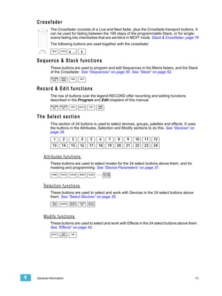
![Patch by Channel
Patching by channel is just as simple as patching by dimmer. The only difference is that the
starting point is the intensity channel. By doing it Live you can check what is patched to
each intensity channel, and then patch or unpatch more dimmer outputs to this channel.
Step 1: Open the Patch:
Menu>Patch>[Patch by channel]
Step 2: Choose between Live and Blind mode using encoder wheel 3.
Press (MENU) to confirm.
Step 3: Patching is done in the left LCD. The right LCD shows all dimmer outputs
patched to the currently selected channel - use encoder wheel 3 to scroll if there
are more than three dimmer outputs patched to the same intensity channel.
Menu choice Console Feedback
CH. Wheel 1 Select a channel to patch or unpatch. The
corresponding DMX output will be selected
immediately when the wheel is moved. D1-
D24 can be selected as well. See Note.
DMX Wheel 2 Select a DMX output to patch to the selected
channel. If it is already patched there is an “*”
before the number as in the image above.
[U1]> MORE Toggles the DMX universe between 1 and 2.
[UNPATCH] SEL Press to patch or unpatch the currently
selected channel to the currently selected
DMX output and universe.
Note: You can patch any of the Device Intensity channels D1-D24 to conventional lights if you
aren’t using these channels for devices.
2 Setup 21](https://image.slidesharecdn.com/smartfademlv11usermanualreva-100714162035-phpapp02/85/Smart-fademl-v1_1_user_manual_reva-27-320.jpg)
![Patch Independents
Independent buttons IND 1 and IND 2 provide two outputs separated from all other controls.
They are intended to operate devices such as smoke machines, tab tracks, cue lights, etc.
• SOLO does not affect these outputs.
• The state or result of the 2 independent outputs is not recordable.
The Default Patch
SmartFadeML defaults to the last outputs in DMX universe 1 for the independents.
IND 1 = DMX 511
IND 2 = DMX 512
This is easy to remember and provides immediate control with two outputs. It is also
possible to create a custom patch by assigning any DMX outputs to the independents.
Set up Independents
They are patched and set up in the Independents menu.
Menu>Independents>[Patch to]
Menu choice Console Feedback
IND 1 Wheel 1 Choose output for Independent 1.
<[U1] SEL Toggles the DMX universe for Independent 1
between 1 and 2.
[U1]> MORE Toggles the DMX universe for Independent 2
between 1 and 2.
IND 2 Wheel 2 Choose output for Independent 2.
Button behaviour
Menu choice Console Feedback
[Button mode] Wheels 1 & 2
[Master mode] Wheels 1 & 2
Sets if BLACKOUT and MASTER
fader will affect or not.
[Set Level] Wheels 1 & 2
22 SmartFadeML v1.1 User Manual](https://image.slidesharecdn.com/smartfademlv11usermanualreva-100714162035-phpapp02/85/Smart-fademl-v1_1_user_manual_reva-28-320.jpg)
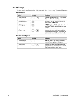
![Device Commands
Device commands like Lamp On, Lamp Off and Reset are done from the Device menu. The
currently selected Devices are affected. See “Select Devices” on page 35.
Menu>Devices>Device Commands>[Lamp On]..[Lamp Off]..[Reset]
View/Modify Device Patch
To check DMX addresses and modify the patch of single devices, open the View/Modify
Patch menu:
Menu>Patch>Patch Devices>View/Modify Patch
These are the options. NOTHING is changed unless (MENU) is pressed and confirmed.
Menu choice Console Feedback
Select a device Wheel 1 As the device number is changed, the rest of
the settings will update to reflect each device.
Universe 1 or 2 MORE Toggles the DMX address between DMX uni-
verse 1 and 2.
DMX address Wheel 2 Change DMX address for the device.
Device Settings
You can invert and/or swap pan and tilt functions individually for every device. This is
usually only used when they are not rigged in the same way - to make pan and tilt have the
same result on stage.
These functions are available from the Device Menu. Go to Menu>Devices>
Menu choice Console Feedback
[Invert Pan] Wheel 2 selects device
(DEV).
SEL toggles on/off.
[Invert Tilt] Wheel 2 selects device
(DEV).
SEL toggles on/off.
[Swap Pan/Tilt] Wheel 2 selects device
(DEV).
SEL toggles on/off.
24 SmartFadeML v1.1 User Manual](https://image.slidesharecdn.com/smartfademlv11usermanualreva-100714162035-phpapp02/85/Smart-fademl-v1_1_user_manual_reva-30-320.jpg)
![Console Setup
Erase Functions
Erasing data is done from the Setup menu.
Menu>Setup>[Erase]
The following kind of data can be erased:
• All show data
• Memories
• Sequences
• Stack
• Palettes
Crossfade faders
The direction in which the Crossfade faders advance to the next step in STACK mode is set
in the Setup menu.
Menu>Setup>[Crossfade faders]
There are two choices of behaviour
• Upwards only
• Both ways
Default Times
Default times can be set for
• Fades in Sequences and Stack. See “Default Fade Times” on page 65.
• Speed Limit.
• FCB Sneak time.
DMX Out
See “DMX Out Speed” on page 18.
MIDI Settings
See “MIDI Settings” on page 25.
2 Setup 25](https://image.slidesharecdn.com/smartfademlv11usermanualreva-100714162035-phpapp02/85/Smart-fademl-v1_1_user_manual_reva-31-320.jpg)
![Language
You can choose language for the menus from the Setup menu.
Menu>Setup>Language>[English]
Current choices are
• English
• Français
• Deutsch
• Español
The console will continue to boot with the last selected language until it is changed.
Displays
Display settings are done from the Setup menu.
Menu>Setup>Displays
Menu choice Console Feedback
BUTTON Wheel 1 Button intensities
SCREEN Wheel 2 LCD intensities
CONTRAST Wheel 3 LCD Contrast
Software Version
You can verify what software version your console is running in the Setup menu.
Menu>Setup>[Software version]
26 SmartFadeML v1.1 User Manual](https://image.slidesharecdn.com/smartfademlv11usermanualreva-100714162035-phpapp02/85/Smart-fademl-v1_1_user_manual_reva-32-320.jpg)
![MIDI Setup
SmartFade ML has included MIDI (Musical Instrument Digital Interface) facilities to provide
three primary functions.
• Show control systems: SmartFadeML may be set to respond to MIDI data from a
time-based sequencer or show control system. This can be MSC or functions from the
Basic MIDI implementation of SmartFadeML.
• Synchronising playback of two SmartFadeML: the Memory faders, bumps and the
playback functions of the Stack plus Grand Master and Blackout can be synchronised.
• Sending MIDI controller data: There is a controller patch where any channel in
SmartFadeML can be set to send any MIDI controller 1-127 to control external devices.
For show control and synchronising playback it is normally enough to make a MIDI
connection and start using without having to set up anything.
MIDI Show Contol
MSC is a show control standard within MIDI that usually is used when different devices are
linked in a show control setup. SmartFadeML supports a basic set of Midi Show Control
(MSC) commands. They are both sent and received at all times - regardless of the settings
for MIDI channel.
You can set the MSC Device ID from the MIDI menu.
Menu>Setup>MIDI>[MSC Device ID]
Midi Show Control Commands
• Go
• Stop
• Resume
Synchronising Two SmartFadeML
To synchronise playback of two SmartFadeML consoles, just connect MIDI OUT from
console A to MIDI IN on console B. Now the main playback functions are “mirrored” from
console A to console B.
If you want to be able to playback from B as well, and mirror back to console A - connect
MIDI OUT from console B to console A as well.
There is no MIDI THRU in SmartFadeML - so there will be no “looping” of information.
Functions
• Since MSC is default on so GO, PAUSE and STOP will be synchronised right away.
• In MEM mode the faders and bumps will be synchronised*
• SOLO mode will be synchronised for MEM bumps*
• Grand Master, Blackout and Bumps Master will be synchronised*
* These functions are transmitted from within the Basic MIDI implementation on the
currently set MIDI channel. MIDI channel, page 28, Basic MIDI implementation, page 28.
2 Setup 27](https://image.slidesharecdn.com/smartfademlv11usermanualreva-100714162035-phpapp02/85/Smart-fademl-v1_1_user_manual_reva-33-320.jpg)
![Basic MIDI implementation
A set of controllers and buttons can be sent and received. This can be used both for Show
Control and to Synchronise two SmartFadeML consoles.
Controllers
• 1-48 = Master 1-48 (only in MEM mode)
• 124 = Live fader
• 125 = Next fader
• 126 = Bump Master
• 127 = Grand Master
Program Change
• 0 = Reset the Stack to step 0
• 1-99 = GOTO step 1-99 in the Stack
• 100-111 = Memory pages 1-12
• 124 = Pause
• 125 = Start (GO)
• 126 = B.O. not active
• 127 = B.O. active
Note on/off
• 0-47 = MEM bumps 1-48 (only in MEM mode)
MIDI channel
The Basic and Advanced MIDI functions apart from MSC are sent and received on the
same MIDI channel. This is set in the MIDI menu.
Menu>Setup>MIDI>[MSC Device ID]
Press OK
Use the wheel 1 to select MIDI channel 1-16 and press OK to confirm.
28 SmartFadeML v1.1 User Manual](https://image.slidesharecdn.com/smartfademlv11usermanualreva-100714162035-phpapp02/85/Smart-fademl-v1_1_user_manual_reva-34-320.jpg)
![Sending MIDI Controllers
This function is designed to allow any control channel in SmartFadeML to control an
external device using any MIDI controller 0-127. This is set up in the Controller Patch.
Menu>Setup>MIDI>[Controller Patch]
Press OK
Use the wheel 1 to select SmartFadeML control channel 1-72, then use wheel 2 to select
MIDI controller 1-127. Press OK to confirm.
Once this is set up the output of this channel will also be transmitted on the MIDI controller
assigned in the Controller Patch.
Note: When a MIDI controller is patched to a channel, the default MIDI implementation function
of this controller is disabled.
2 Setup 29](https://image.slidesharecdn.com/smartfademlv11usermanualreva-100714162035-phpapp02/85/Smart-fademl-v1_1_user_manual_reva-35-320.jpg)


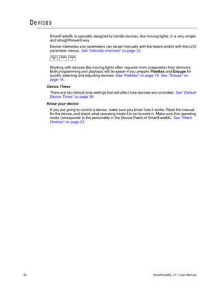
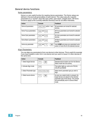
![Adjust Channel Range
It’s possible to select any channel range and adjust proportionally in the Channel menu.
Menu>Channels>[Adjust Channel Range]
Menu choice Console Feedback
START Wheel 1 Select first channel in range
END Wheel 2 Select last channel in range
[All] SEL Selects all channels as channel range.
Adjust LEVEL Wheel 3 Adjust the levels proportionally
Set Channel Range
It’s possible to select any channel range and set levels in the Channel menu.
Menu>Channels>[Set Channel Range]
Menu choice Console Feedback
START Wheel 1 Select first channel in range
END Wheel 2 Select last channel in range
[All] SEL Selects all channels as channel range.
Set LEVEL Wheel 3 As soon as the wheel is moved, all channels
in the range will instantly be set to this level.
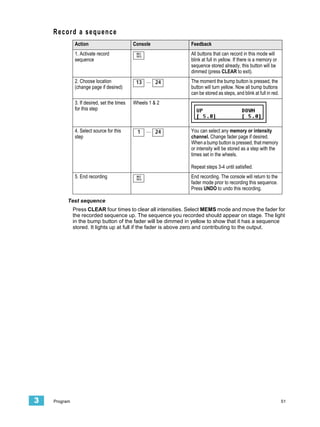
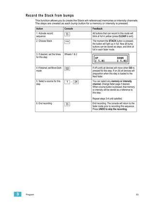
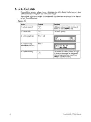
3 Program 33](https://image.slidesharecdn.com/smartfademlv11usermanualreva-100714162035-phpapp02/85/Smart-fademl-v1_1_user_manual_reva-39-320.jpg)
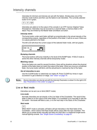
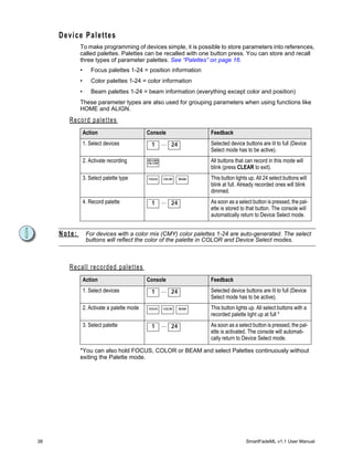
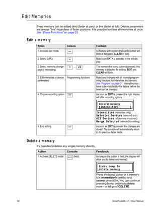
![Device Parameters
A device in SmartFadeML can have up to 48 parameters such as pan, tilt, gobo etc. These
parameters are automatically mapped to the controls by the personality in the device patch.
Parameters for the selected devices are always moved to the last issued value in an LTP
manner (Latest Takes Precedence). They are not affected by the Master Fader or Blackout
button.
P a r a m e t e r s i n t h e f a de r s
When a device is selected all its parameters are mapped into two PARAM fader pages.
PARAM PARAM
1 2
As soon as one of these fader pages is activated (button is lit) the bump button will light up
under the fader of any parameter that is available in the currently selected devices.
The parameter of each fader is printed on the console frontpanel, under the fader.
PARAM 1 parameters are printed below the buttons and PARAM 2 above. For example,
fader 1 in PARAM 1 = Intensity.
When a fader is moved, that parameter will jump to the value of the fader (which may be
unwanted behaviour). To adjust parameters relative to their current value, use the encoder
wheels and LCDs.
Bump buttons
The bump buttons will toggle a parameter between zero and full when PARAM 1 or 2 are
held.
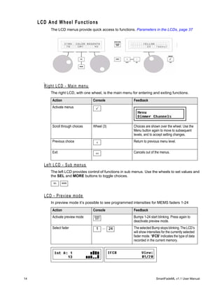
Parameters in the LCDs
As soon as a device is selected, both LCD’s provide parameter control with the encoder
wheels. This is necessary if you want to adjust parameters relative to their current position.
The left LCD shows the current parameter type in the top middle (Focus in this example).
The top right corner of the right LCD shows the number of this menu, and underneath is the
number of available sub-menus. In this example Coarse is the current sub-menu, and it’s
sub-menu number 1 out of 2 (1/2).
Parameters that do not exist in the currently selected device(s) are displayed [---].
Navigation buttons
Action Console Feedback
Next parameter menu SEL The next parameter menu is selected and dis-
played top/mid in the left LCD.
Sub-menus MORE Sub-menus are displayed bottom/mid in the
left LCD, and the button lights up.
3 Program 37](https://image.slidesharecdn.com/smartfademlv11usermanualreva-100714162035-phpapp02/85/Smart-fademl-v1_1_user_manual_reva-43-320.jpg)

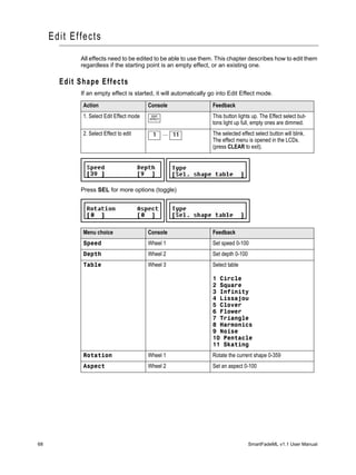
![Snapshots
The Snapshot function is designed to make it easy to capture the current output, and store
it as a memory at a later point.
• Snapshot can be pressed at any time inside any menu or function.
Snapshot captures a complete state of all output channels and stores them into a buffer.
This buffer has 10 snapshot positions. If pressed 11 times, Snapshot will overwrite the 1st
Snapshot in the buffer.
The Snapshot button
The button is off when there are no Snapshots recorded. As soon as there is a Snapshot
recorded it will light at full in red.
Record a Snapshot
Action Console Feedback
Record the current output SNAP
SHOT
The current output is recorded. The display
will momentarily display a confirmation.
The Snapshot button will light up as soon as
there are one or more Snapshots.
Copy a Snapshot to a Memory
It’s possible to copy a Snapshot to a memory in the Memories menu.
Menu>Memories>[Copy Snapshots]
Use SEL to choose between Live and Blind mode, press OK to confirm.
Menu choice Console Feedback
SNAP Wheel 1 Select snapshot 1-10
TARGET Wheel 2 Select target fader page and memory. Press
OK twice to confirm.
Clear all Snapshots
Action Console Feedback
Clear the Snapshot buffer CLEAR and SNAP
SHOT
The Snapshot buffer is immediately deleted,
and cannot be undone.
3 Program 49](https://image.slidesharecdn.com/smartfademlv11usermanualreva-100714162035-phpapp02/85/Smart-fademl-v1_1_user_manual_reva-55-320.jpg)
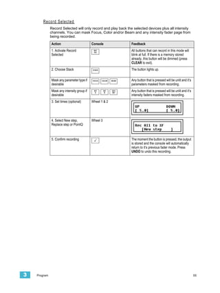

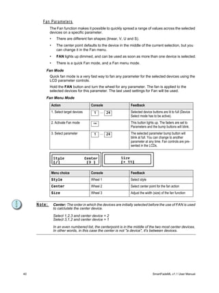
![C o p y a M e m or y
Action Console Feedback
1. Activate Copy mode COPY This button lights up. All buttons with content
will blink at full (press CLEAR to exit).
2. Select source memory 1 ... 24 When this button is pressed, all possible tar-
(change page if neces- gets for this copy operation will blink. Empty
sary). ones blink at full, occupied ones are dimmed.
3. Mask any parameter FOCUS COLOR BEAM Any button that is pressed will be unlit and it’s
type if desirable parameters masked from copying.
4. Select target 1 ... 24 As soon as the button is pressed, the source
memory is recorded. The console will auto-
matically return to it’s previous fader mode.
Delete device data from a memory
Action Console Feedback
1. Activate Delete mode DELETE All buttons with content that can be deleted
will blink at full (press CLEAR to exit).
2. Select memory (change 1 ... 24 The moment the bump button is pressed, this
page if necessary). memory is selected for editing. DELETE and
CLEAR will blink.
3. Select devices to delete Device select functions Use any device selection functions to select
the devices you wish to delete.
4. Mask any parameter FOCUS COLOR BEAM Any button that is pressed will be unlit and it’s
type if desirable parameters masked from deleting.
5. End editing DELETE As soon as DELETE is pressed the changes
are stored. The console will automatically
return to it’s previous fader mode.
Default Device Times
There are two types of default device times.
• Speed Limit = A limiting time that sets a maximum speed for any function, mainly to
keep mechanical noise down. This time is used by Move by Dark prepositioning in
sequence/Stack and Home.
• FCB Sneak Time = A time used when activating a palette or using Align.
They are both set in the Default Time menu
Menu>Setup>Default times[SpeedLimit & Sneak]
Use encoder wheel 2 and 3 to set the times. Exit menu when done.
4 Edit 59](https://image.slidesharecdn.com/smartfademlv11usermanualreva-100714162035-phpapp02/85/Smart-fademl-v1_1_user_manual_reva-65-320.jpg)
![M e m or y F C B T i m e s
A memory can have a time for the FCB parameters, that is used (only) when they are
executed with the Bump button in GO mode. See “Memory Bump Modes” on page 75.
Step 1: Press EDIT
Make sure [Times] is selected (press SEL to toggle).
Step 2: Now press a bump button for a memory. The display will change to time setting.
Menu choice Console Feedback
PAGE Wheel 1 Select another fader page (or press a bump)
MEMORY Wheel 2 Select another memory (or press a bump)
FCB TIME Wheel 3 Set the FCB time for the selected memory
Step 3: Press EDIT to exit.
Test the FCB time
If you have set this time to a memory with devices and want to try it, press CLEAR 4 times
to clear the output. Set all memory faders to zero. Select all devices and set to HOME. Set
faders to INT ONLY and bring up the fader for the memory. Activate GO mode. Press the
bump button for the memory where you set an FCB time. The device parameters should
change in this time.
60 SmartFadeML v1.1 User Manual](https://image.slidesharecdn.com/smartfademlv11usermanualreva-100714162035-phpapp02/85/Smart-fademl-v1_1_user_manual_reva-66-320.jpg)
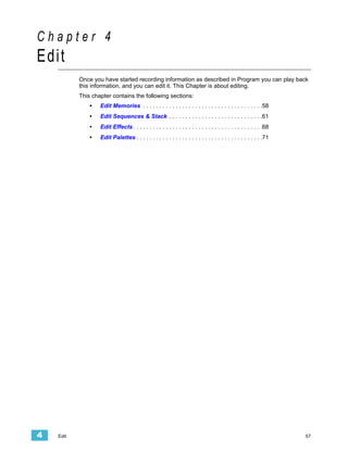
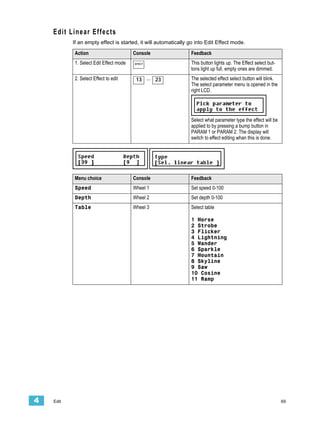
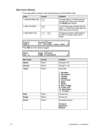
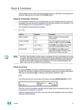
![Edi t Sequences & Stack
Sequence and Stack steps are edited in the same way. The Stack has some extra editing
functions since there are unique Stack states and point cues, which don’t exist in
sequences. To delete all Sequences and the Stack See “Erase Functions” on page 25.
The functions available for modifying Sequence & Stack steps are Edit, Delete, Insert and
Change. For the stack there is also the option of recording up to 9 point Qs between each
step.
Edit the content of a Step
A sequence or Stack step can contain a reference to a memory in a specific page, or a
single channel intensity. The Stack can have a unique memory state as well. Memories can
be edited in the memory fader, or in the step. Steps that reference a single intensity channel
can not be edited, you have to use change instead to change to a different single intensity
channel. Unique Stack steps are edited as described, just like memories.
Step 1: Press EDIT
Make sure [Data] is selected (press SEL to toggle).
Step 2: Select Sequence by pressing a bump button, or press STACK.
Step 3: Select Step (wheel 2) and Edit (wheel 3). The content of the selected step will
be selected for editing.
Press (MENU) to confirm.
Step 4: The left display will show the intensities in the selected fader page of this step.
Use the intensity faders and Device controls to edit the memory.
Press EDIT to confirm.
Step 5: You now have the choice of recording only intensities, all devices or only the
selected devices. If you choose Selected Devices you can mask FCB in the
same way as when using the Rec Sel button. See “Record a memory” on
page 47.
Press (MENU) to confirm. You will automatically exit the Edit function and return
to the fader mode previous to pressing EDIT the first time.
4 Edit 61](https://image.slidesharecdn.com/smartfademlv11usermanualreva-100714162035-phpapp02/85/Smart-fademl-v1_1_user_manual_reva-67-320.jpg)
![Delete a Step
Step 1: Press EDIT
Make sure [Data] is selected (press SEL to toggle).
Step 2: Select Sequence by pressing a bump button, or press STACK.
Step 3: Select Step (wheel 1) and Insert (wheel 3).
Press (MENU) to confirm.
Step 4: You will be asked to confirm deleting the selected step.
Press (MENU) to confirm.
Step 5: Exit by pressing EDIT or continue with Actions from Step 2. You can press UNDO
to skip and revert to the data previous to this action.
Insert a Step
Step 1: Press EDIT
Make sure [Data] is selected (press SEL to toggle).
Step 2: Select Sequence by pressing a bump button, or press STACK.
Step 3: Select Step (wheel 1) and Insert (wheel 3). The new step will be inserted after
the selected step.
Press (MENU) to confirm.
Step 4: Press any bump in any fader page and fader mode.
The step is inserted as soon as the bump button is pressed.
Step 5: Press EDIT to complete, or continue with Actions from Step 2. You can press
UNDO to skip and revert to the data previous to this action.
62 SmartFadeML v1.1 User Manual](https://image.slidesharecdn.com/smartfademlv11usermanualreva-100714162035-phpapp02/85/Smart-fademl-v1_1_user_manual_reva-68-320.jpg)
![Insert a PointQ
Step 1: Press EDIT
Make sure [Data] is selected (press SEL to toggle).
Step 2: Select Stack by pressing STACK.
Step 3: Select Step (wheel 1) and Insert PointQ (wheel 3). The new PointQ step will be
inserted after the selected step.
Press (MENU) to confirm.
Step 4: Use wheel 2 to select which PointQ (0.1-0.9), and then press any bump in any
fader page and fader mode.
The PointQ is stored as soon as the bump button is pressed.
Step 5: Press EDIT to complete, or continue with Actions from Step 2.
Change the content of a Step
Use this function to change the memory or channel content of a step to another content.
Step 1: Press EDIT
Make sure [Data] is selected (press SEL to toggle).
Step 2: Select Sequence by pressing a bump button, or press STACK.
Step 3: Select Step (wheel 1) and Insert (wheel 3). The content of the selected step will
be changed for a new content.
Press (MENU) to confirm.
Step 4: Press any bump in any fader page and fader mode.
The change is stored as soon as the bump button is pressed.
Step 5: Press EDIT to exit, or continue with Actions from Step 2. You can press UNDO
to skip and revert to the data previous to this action.
4 Edit 63](https://image.slidesharecdn.com/smartfademlv11usermanualreva-100714162035-phpapp02/85/Smart-fademl-v1_1_user_manual_reva-69-320.jpg)
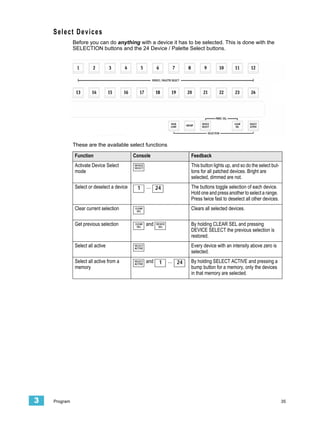
![Copy a Sequence
Action Console Feedback
1. Activate Copy mode COPY This button lights up. All buttons with content
will blink at full (press CLEAR to exit).
2. Select source sequence 1 ... 24 When this button is pressed, all possible tar-
(change page if neces- gets for this copy operation will blink. Empty
sary). ones blink at full, occupied ones are dimmed.
3. Select target 1 ... 24 As soon as the button is pressed, the source
sequence is recorded. The console will auto-
matically return to it’s previous fader mode.
Run Modes
There are three run modes for a Sequence: Manual, One Shot and Loop (default). The
Stack only has Manual and One Shot. Run modes are set from the Sequences menu.
Step 1: Press EDIT
Make sure [Times] is selected (press SEL to toggle).
Step 2: Now press a bump button for a sequence. You will get this display.
Step 3: Use encoder wheel 3 to select [Run mode]. Press (MENU) to confirm.
Step 4: Select run mode using encoder wheel 3. Press (MENU) to confirm.
Menu choice Console Feedback
Loop Wheel 3 Default behaviour for Sequences (not avail-
able for the Stack). The Sequence will loop
from the last step back to the first, endlessly.
Manual Wheel 3 Default behaviour for the Stack. A press of
the GO key is required to advance to the next
step. Sequences in this mode use the bump
button to advance to the next step.
One Sht Wheel 3 Runs sequences through one full cycle only.
Stack will run automatically through the cue
list once with a single press of GO.
Step 5: Done. Press EDIT to exit.
64 SmartFadeML v1.1 User Manual](https://image.slidesharecdn.com/smartfademlv11usermanualreva-100714162035-phpapp02/85/Smart-fademl-v1_1_user_manual_reva-70-320.jpg)
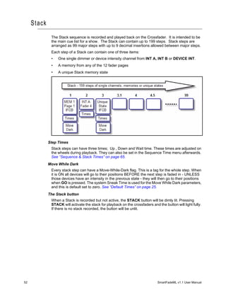
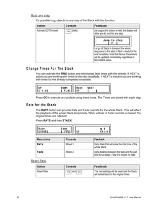
![Sequence & Stack Times
Each Sequence step can have three times, Up, Down and Wait. In addition to these times
there is an overall Rate and Fade time that affect the whole Sequence. These times are set/
changed during playback.
Default Fade Times
Default fade times are set from the Setup menu.
Menu>Setup>Default Times>[Fade Times]
Menu choice Console Feedback
UP Wheel 1 Default Up times
DOWN Wheel 2 Default Down times
WAIT Wheel 3 Default Wait times
Set Times Live
The TIME button allows you to change the fade times for each step of the Stack during
playback. This can be done for the last fade (normal) or the next fade (NEXT active).
Press TIME and then STACK.
The set times are stored.
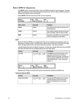
Rate
The RATE button can provide Rate and Fade controls for the Stack. This will affect the
playback of the whole Sequence or Stack.
Press RATE and then STACK.
Menu choice Console Feedback
Rate Wheel 1 Set a Rate that will scale the total time of the
whole Stack.
Fade Wheel 2 Set a balance between the fade and the wait
time for all steps. Fade 0% means no fade.
4 Edit 65](https://image.slidesharecdn.com/smartfademlv11usermanualreva-100714162035-phpapp02/85/Smart-fademl-v1_1_user_manual_reva-71-320.jpg)
![Edit step times blind
It is possible to edit the times blind, for each step of a Sequence or Stack. This is done with
the EDIT function.
Step 1: Press EDIT
Make sure [Times] is selected (press SEL to toggle).
Step 2: Now press a bump button for a sequence. You will get this display.
Step 3: Use encoder wheel 3 to select [Single step]. Press (MENU) to confirm.
Step 4: Use encoder wheel 3 to select a step.
Press (MENU) to confirm.
Step 5: Use the encoder wheels to set times for the selecte step. Exit the menus when
done.
Menu choice Console Feedback
UP Wheel 1 Up time
DOWN Wheel 2 Down time
WAIT Wheel 3 Wait time
Step 6: Done. Press EDIT to exit.
66 SmartFadeML v1.1 User Manual](https://image.slidesharecdn.com/smartfademlv11usermanualreva-100714162035-phpapp02/85/Smart-fademl-v1_1_user_manual_reva-72-320.jpg)
![Global Time for all steps
It is possible to edit the times globally for all steps of a Sequence or Stack. This is set with
the EDIT functions. All previous timing information is replaced and cannot be undone.
Step 1: Press EDIT
Make sure [Times] is selected (press SEL to toggle).
Step 2: Now press a bump button for a sequence. You will get this display.
Step 3: Use encoder wheel 3 to select [All steps]. Press (MENU) to confirm.
Step 4: Use the wheels to set Global Timing for all steps of the selecte Sequence or
Stack.
Menu choice Console Feedback
UP Wheel 1 Up time for all steps
DOWN Wheel 2 Down time for all steps
WAIT Wheel 3 Wait time for all steps
Step 5: Press (MENU) to store.
Press (MENU) to confirm
Step 6: Done. Press EDIT to exit.
4 Edit 67](https://image.slidesharecdn.com/smartfademlv11usermanualreva-100714162035-phpapp02/85/Smart-fademl-v1_1_user_manual_reva-73-320.jpg)


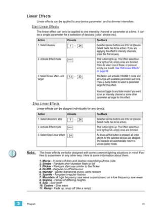
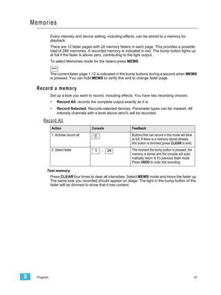
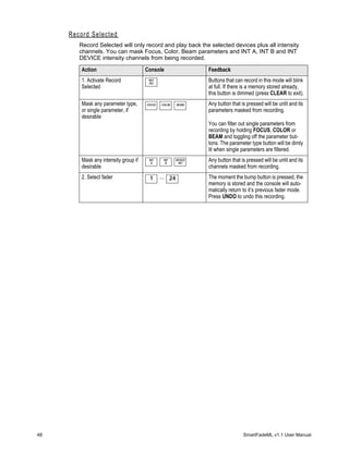
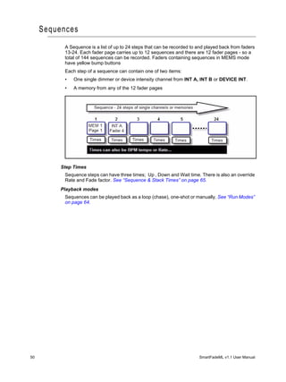
This document is the user manual for the Control Console version 1.1, released in June 2007 by Electronic Theatre Controls, Inc. It provides instructions on how to operate the control console, including setup procedures, programming functions, and saving/loading shows to an SD memory card. The manual is intended to explain all functionality of the control console to users.


