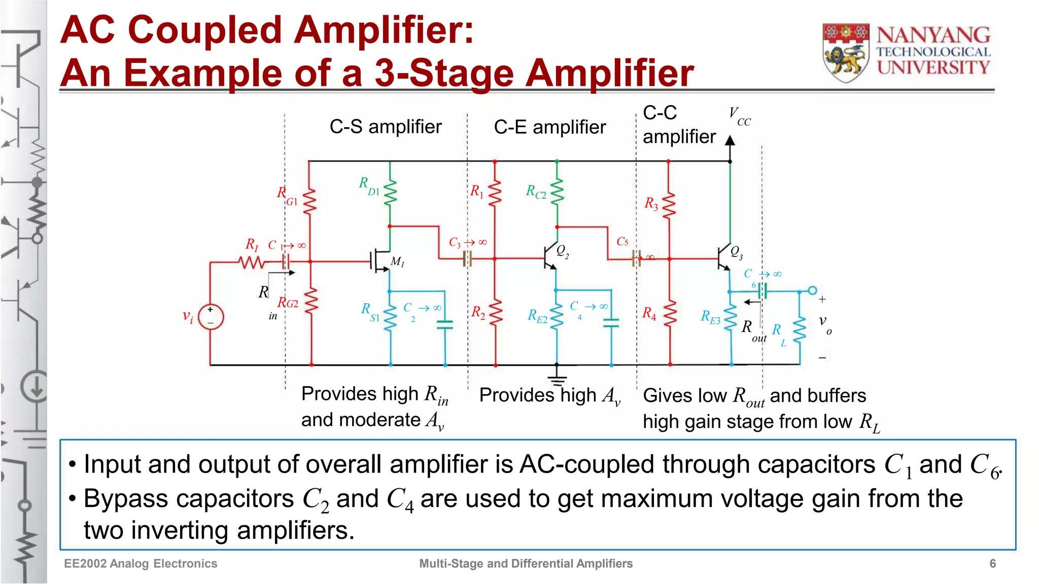
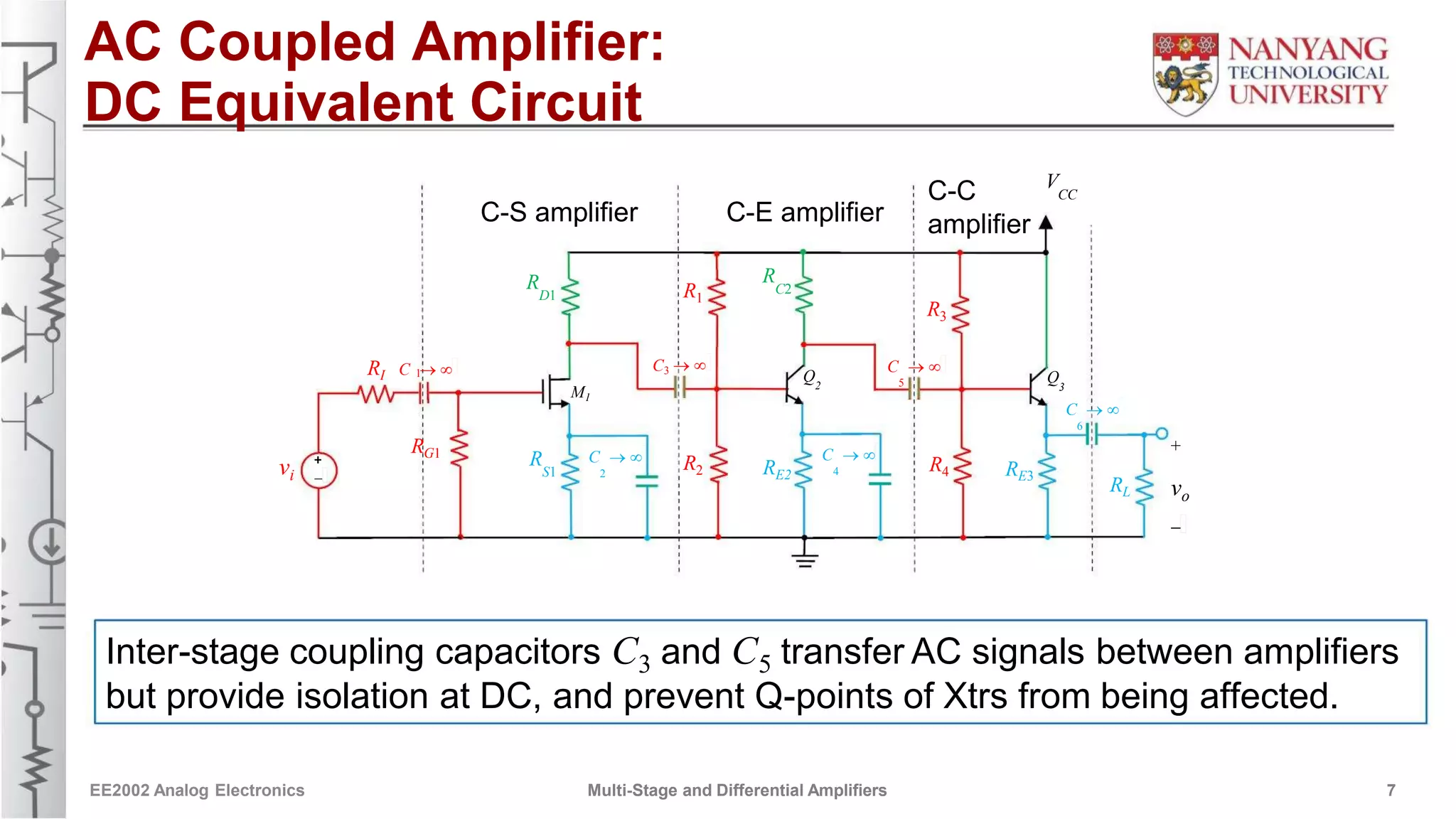
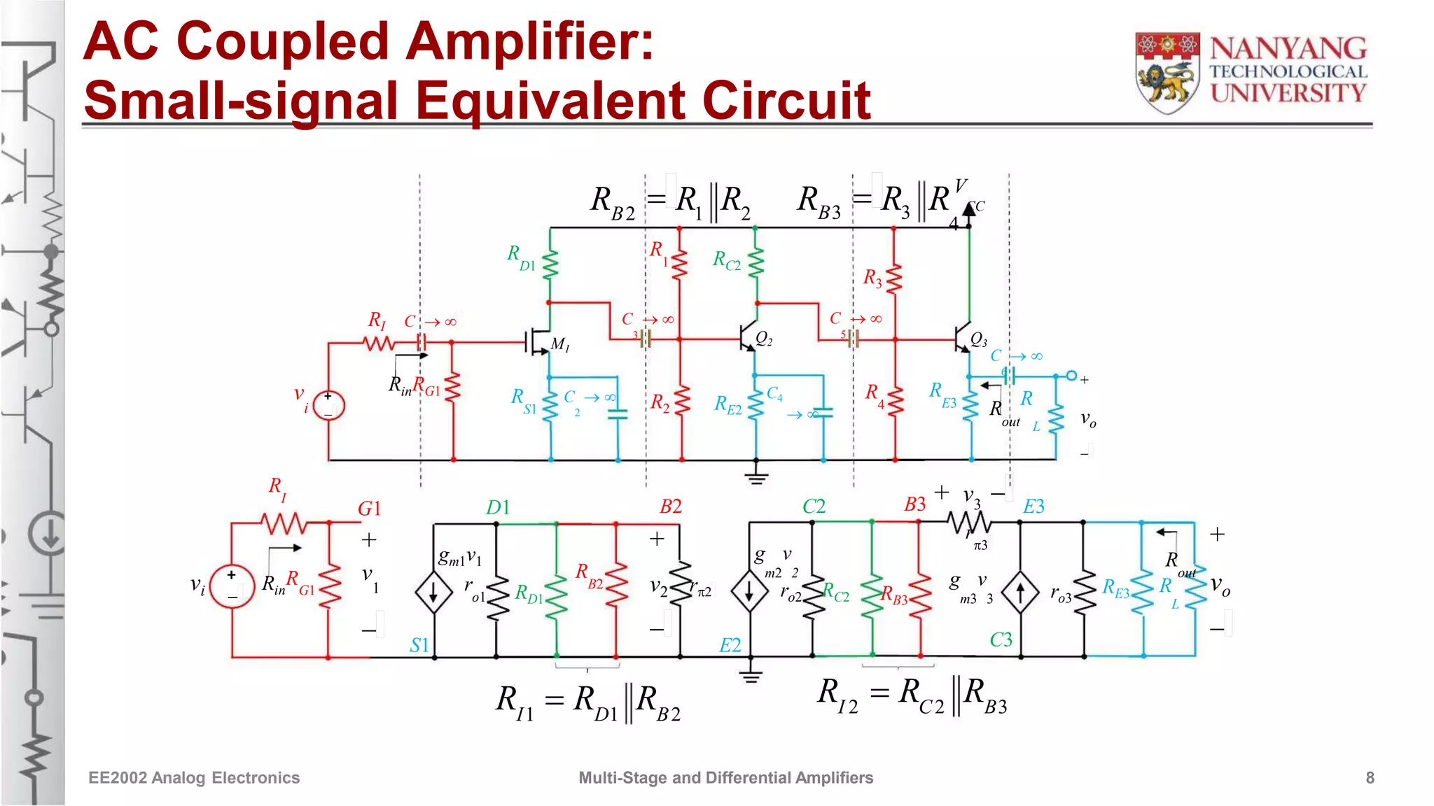
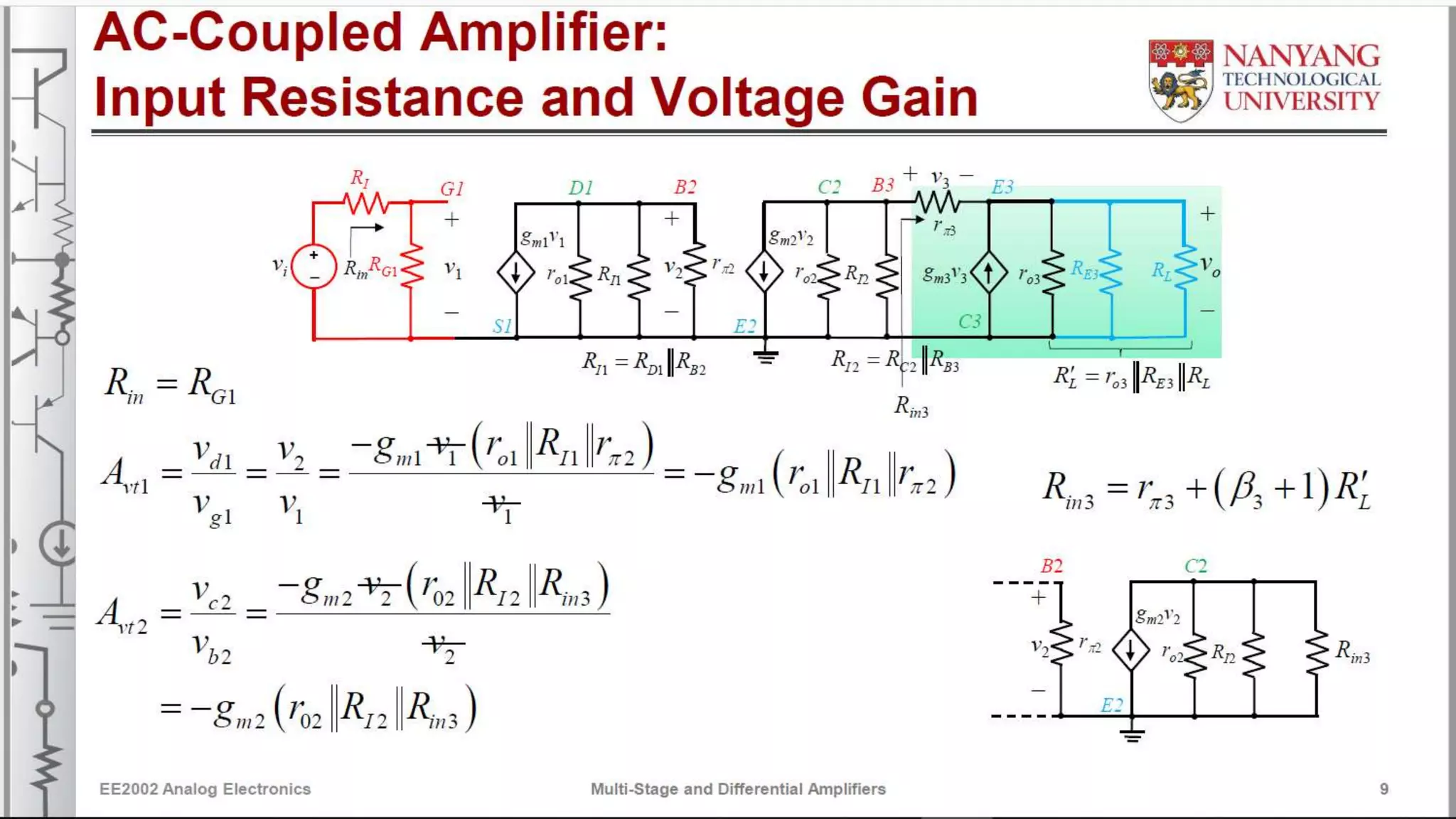
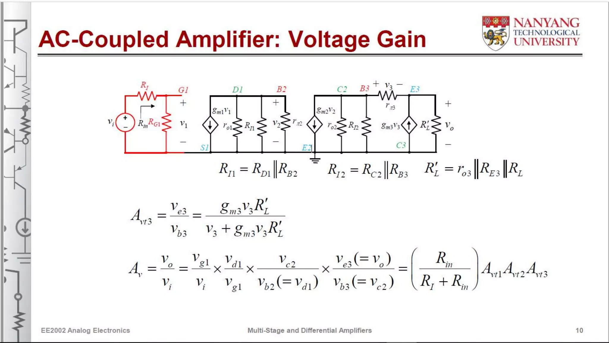
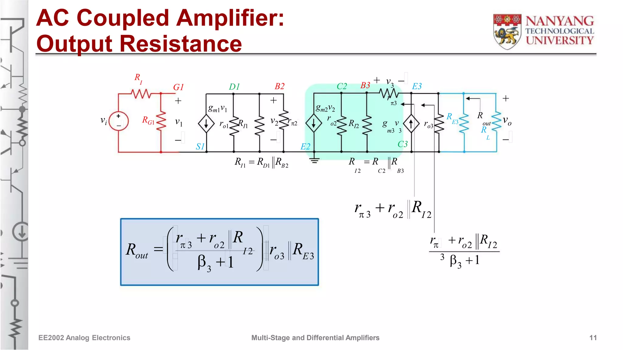
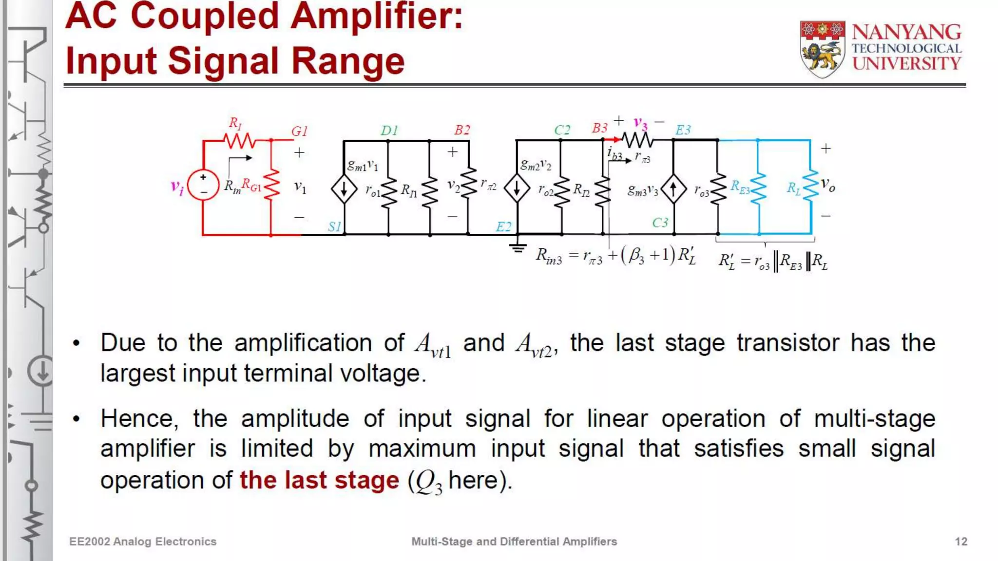
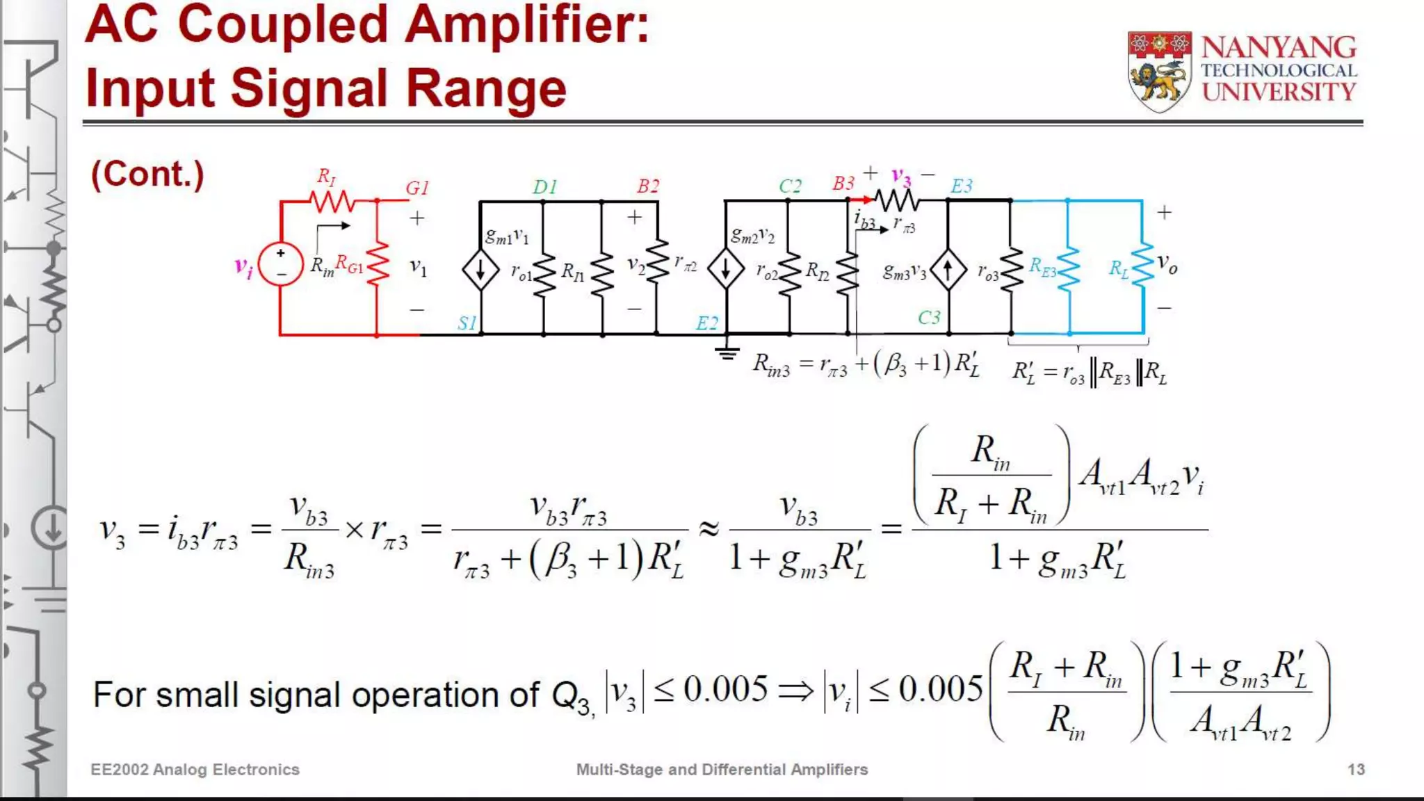
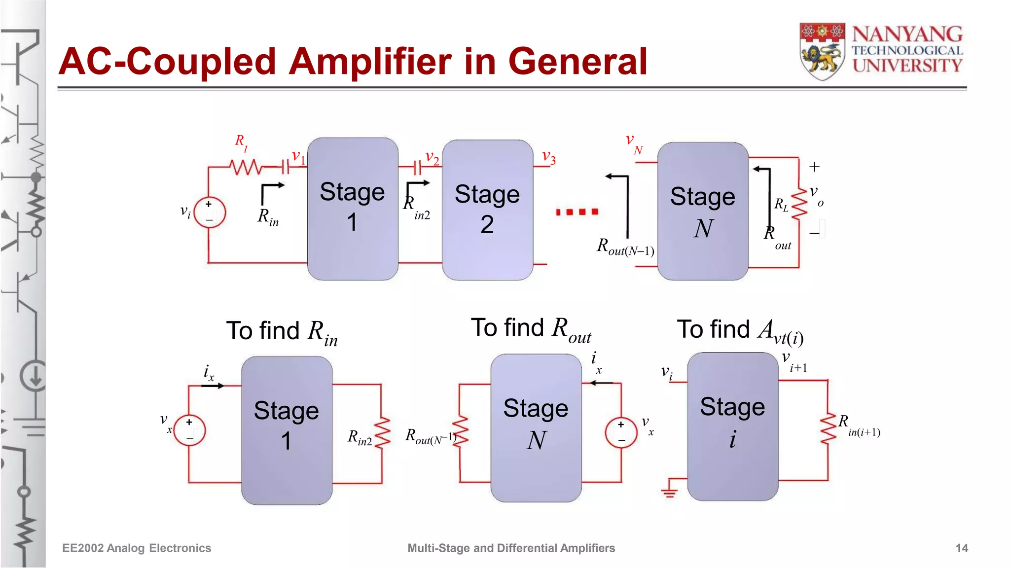
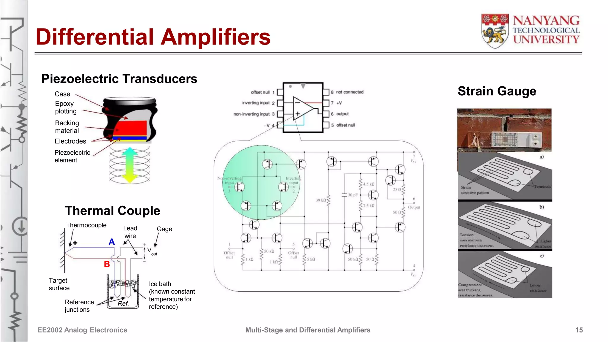
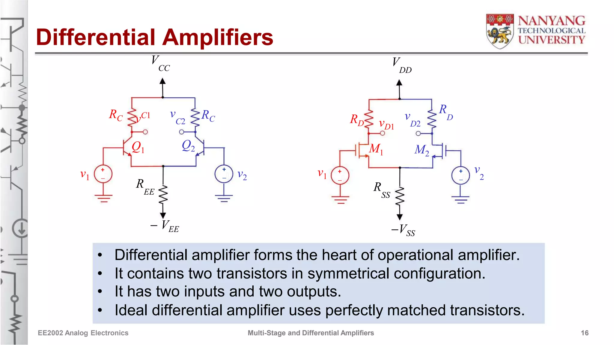
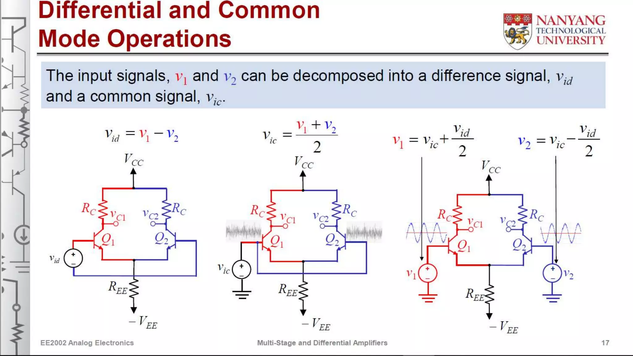
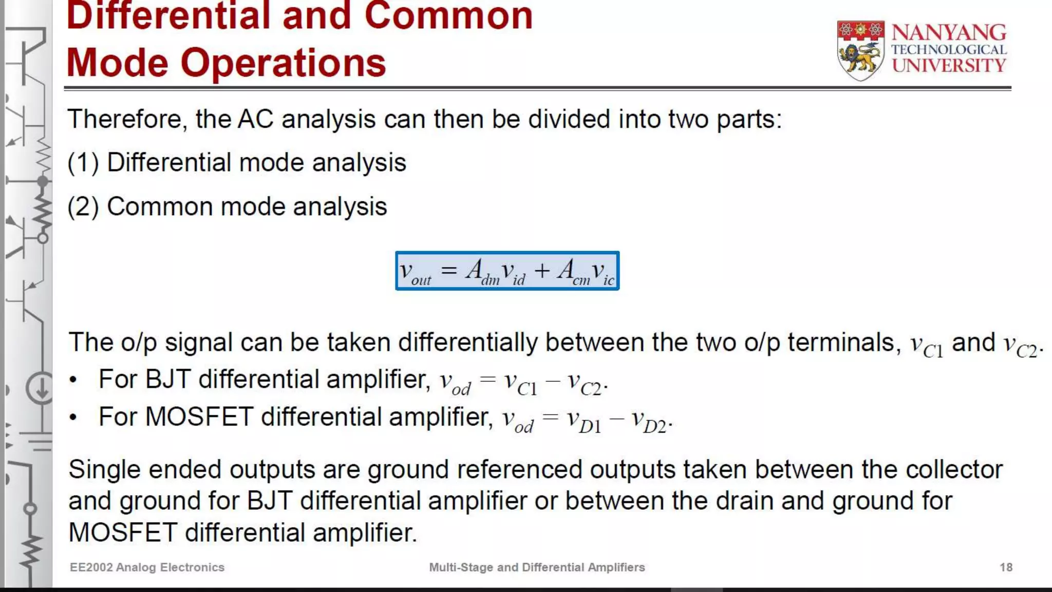
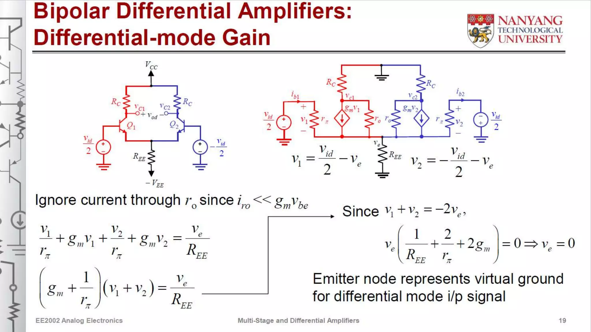
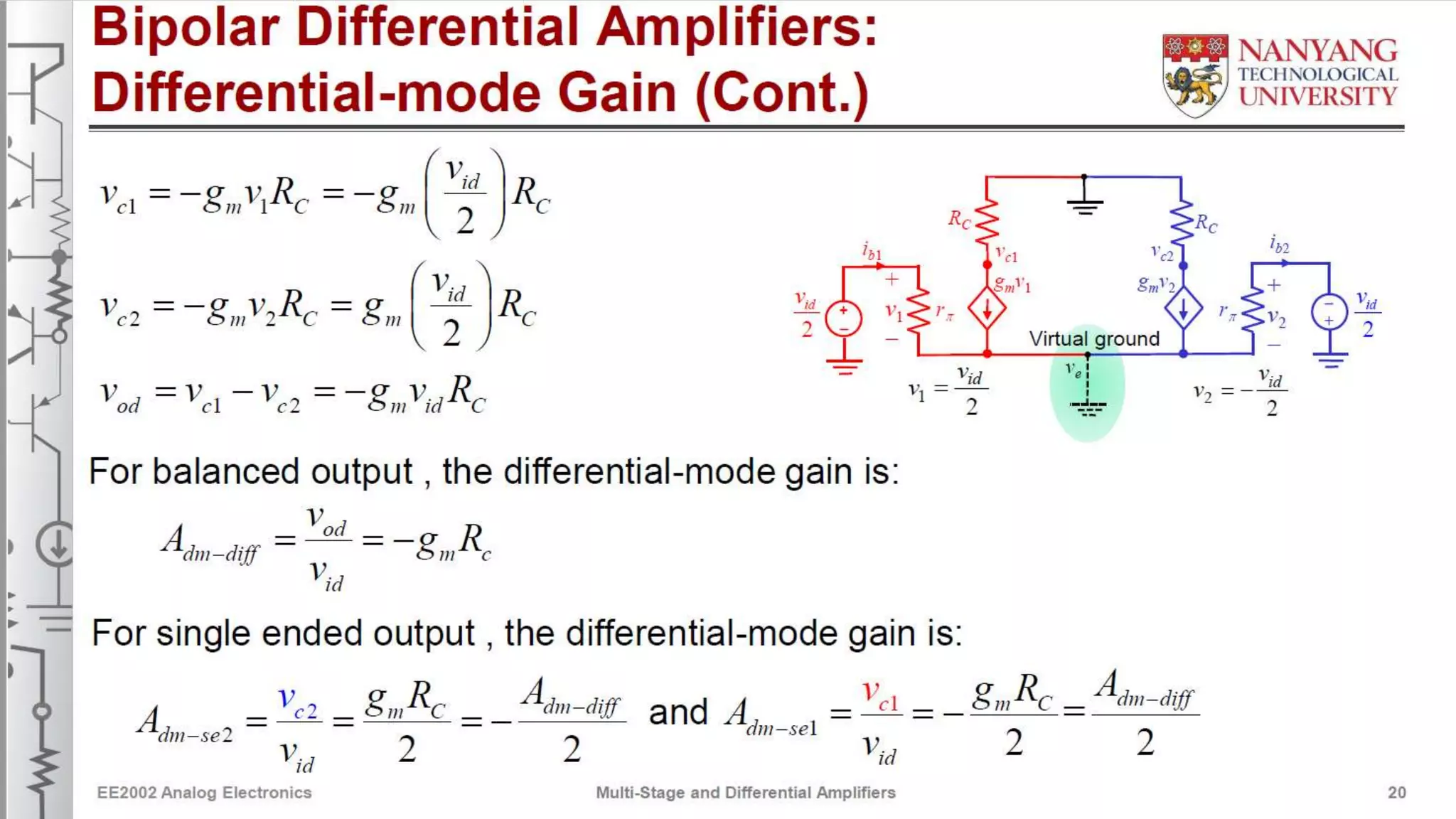
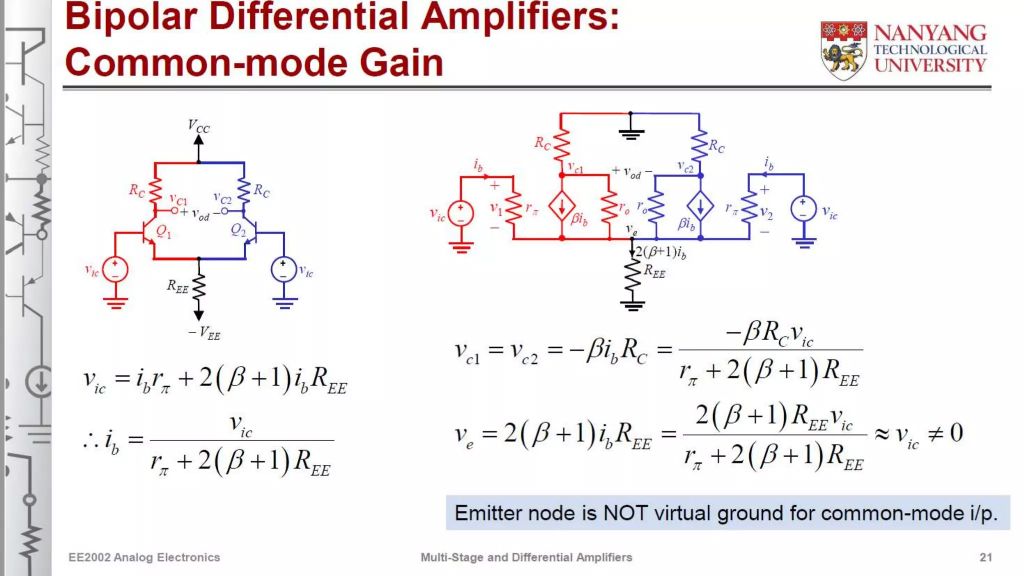
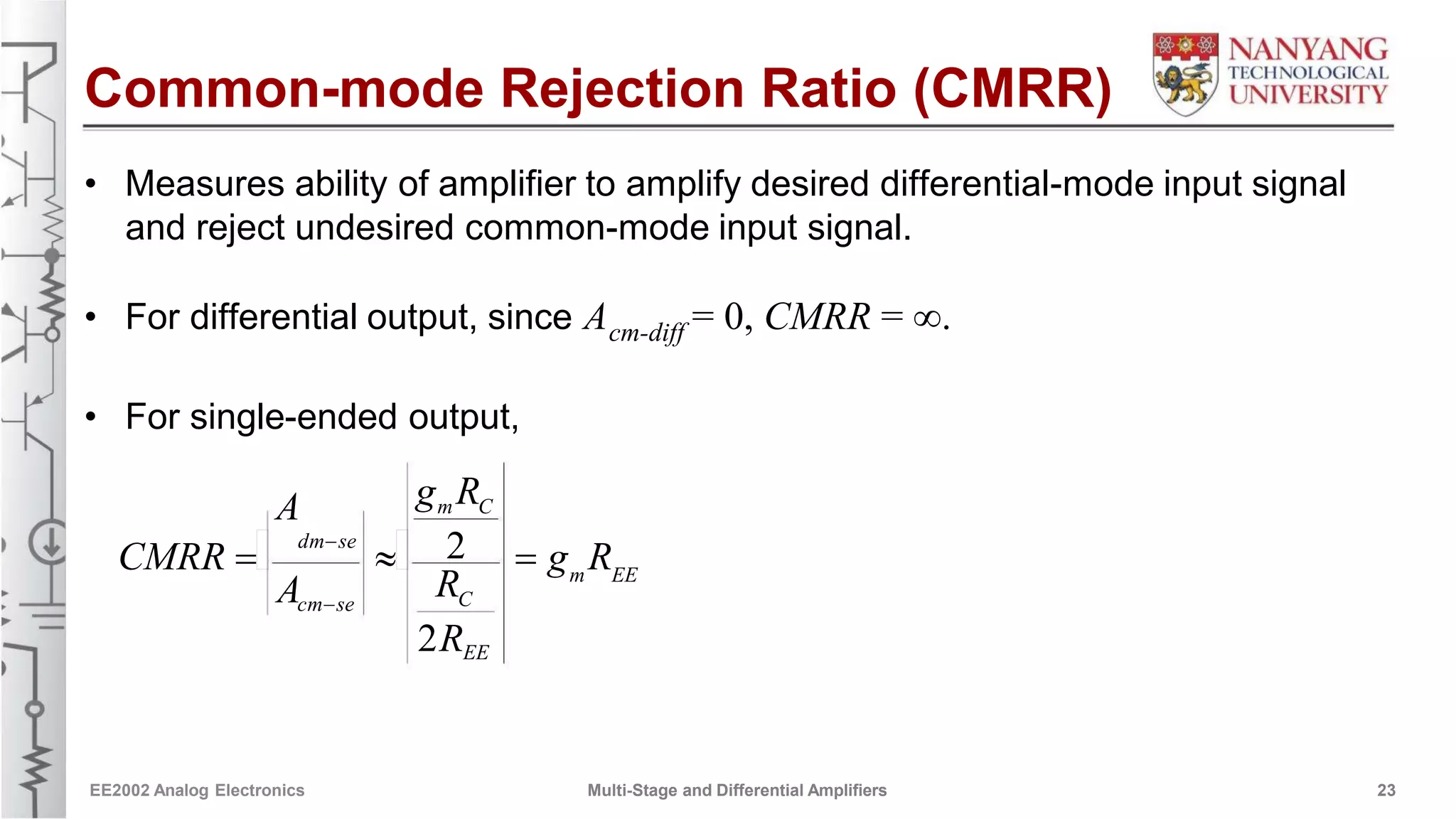
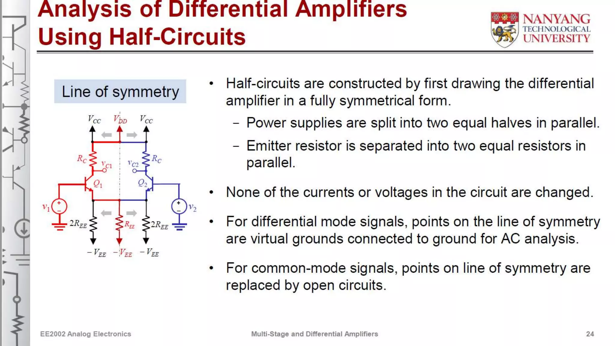
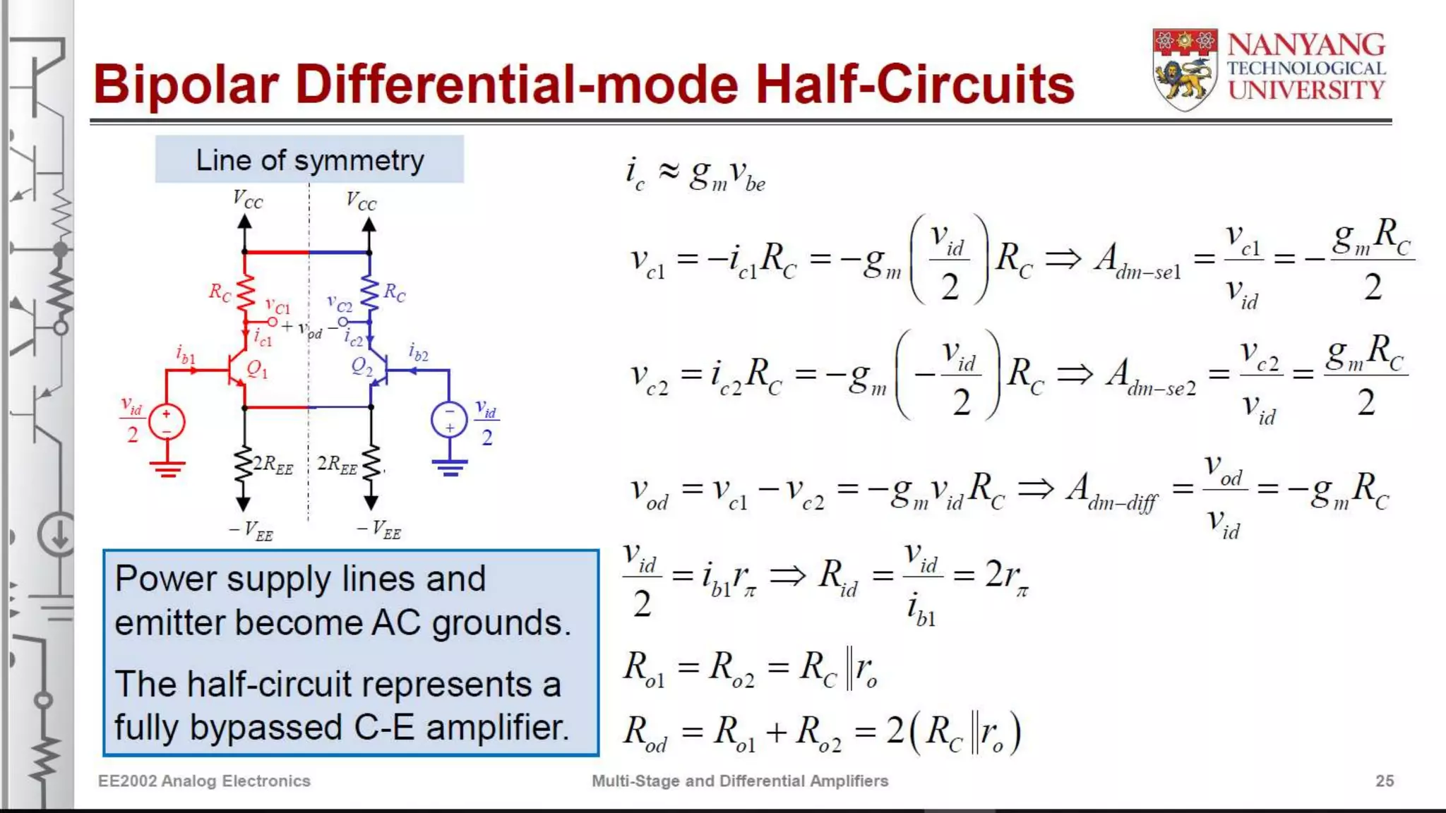
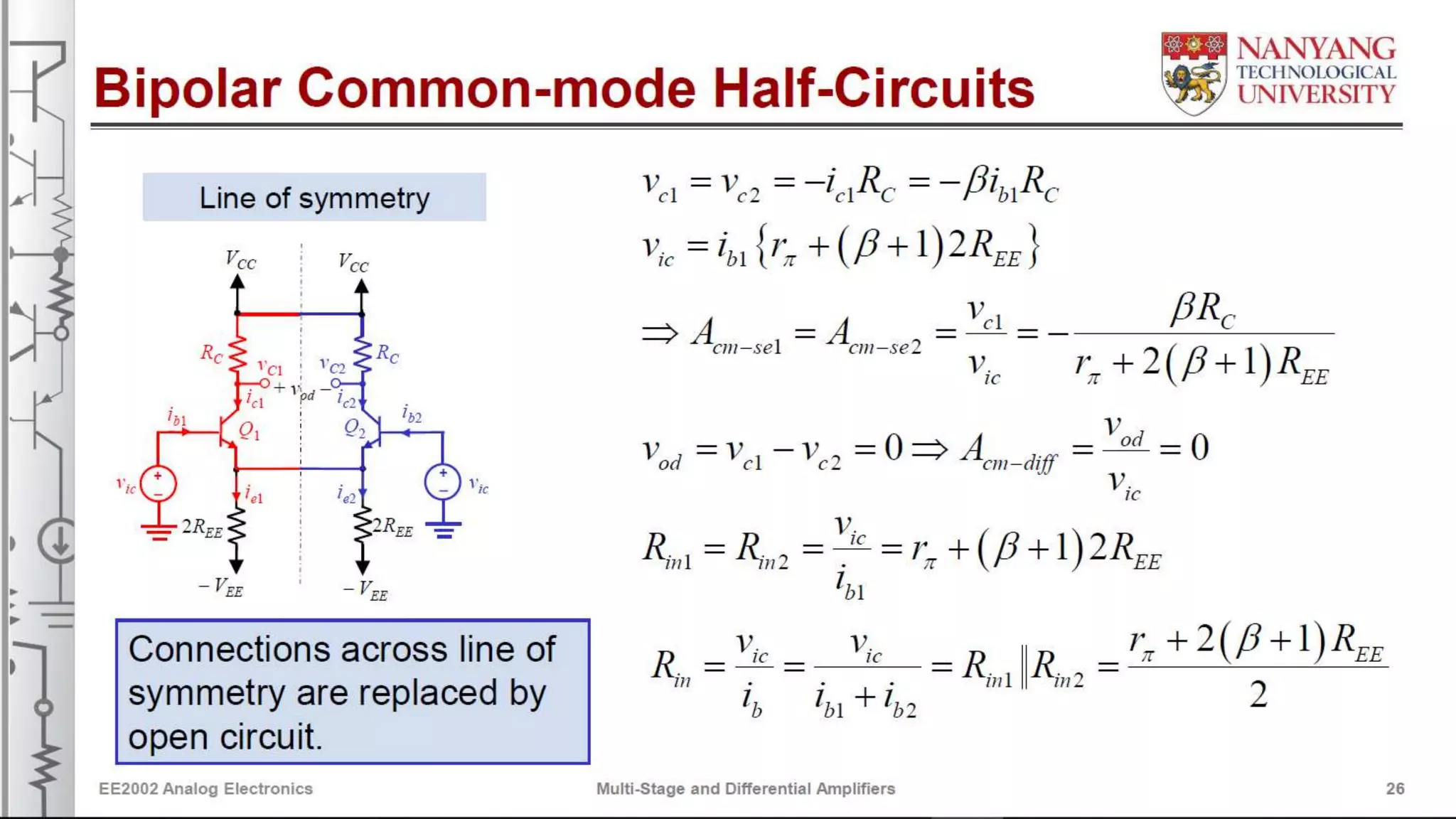
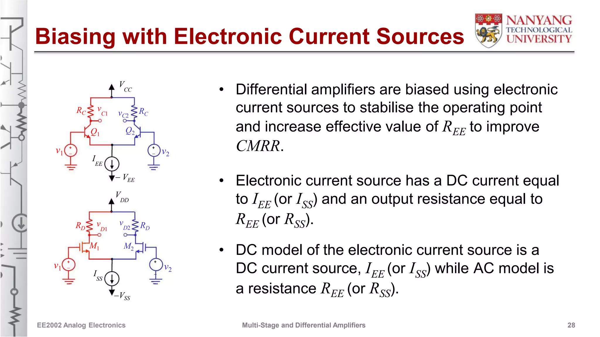
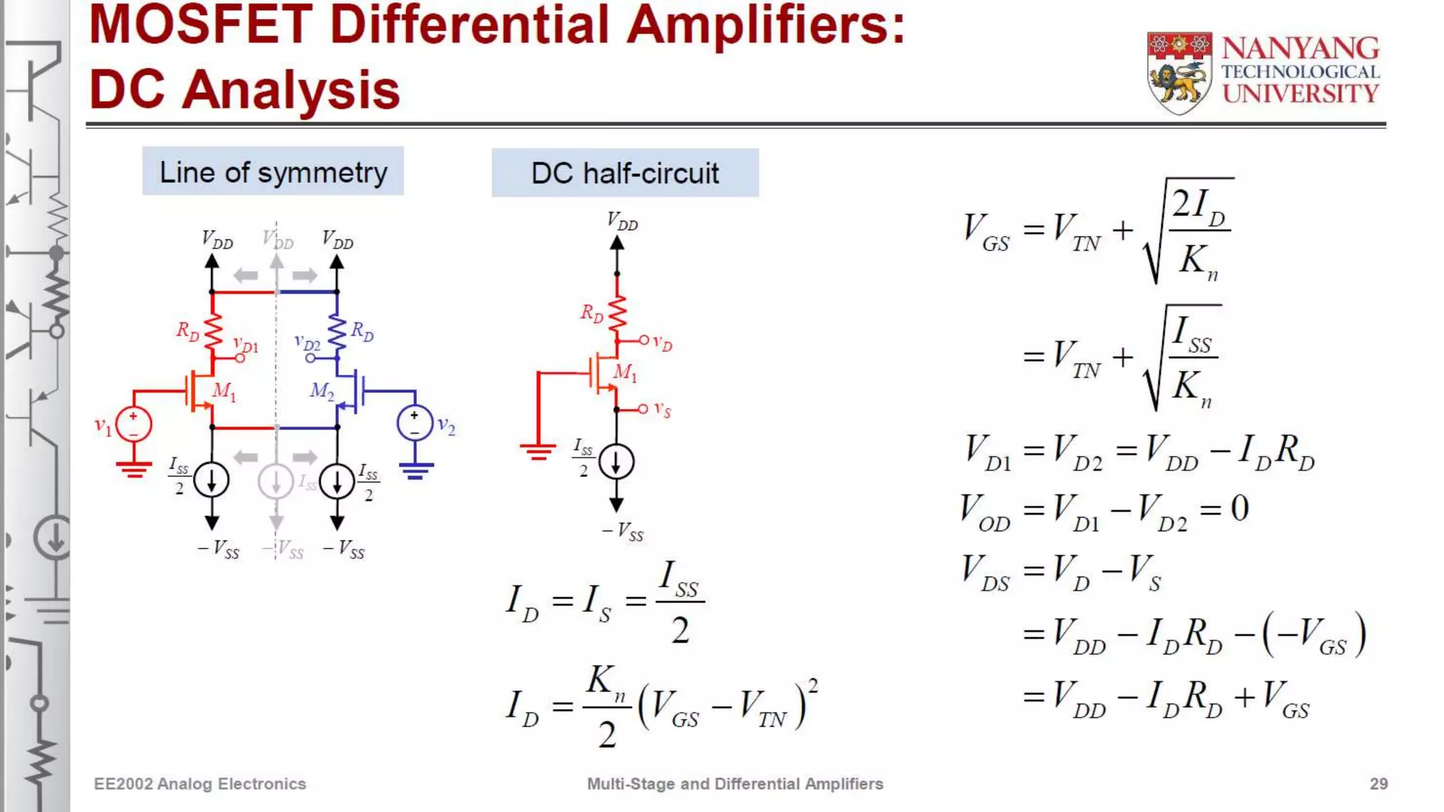
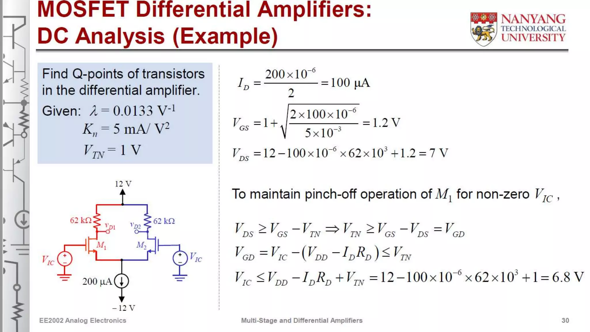
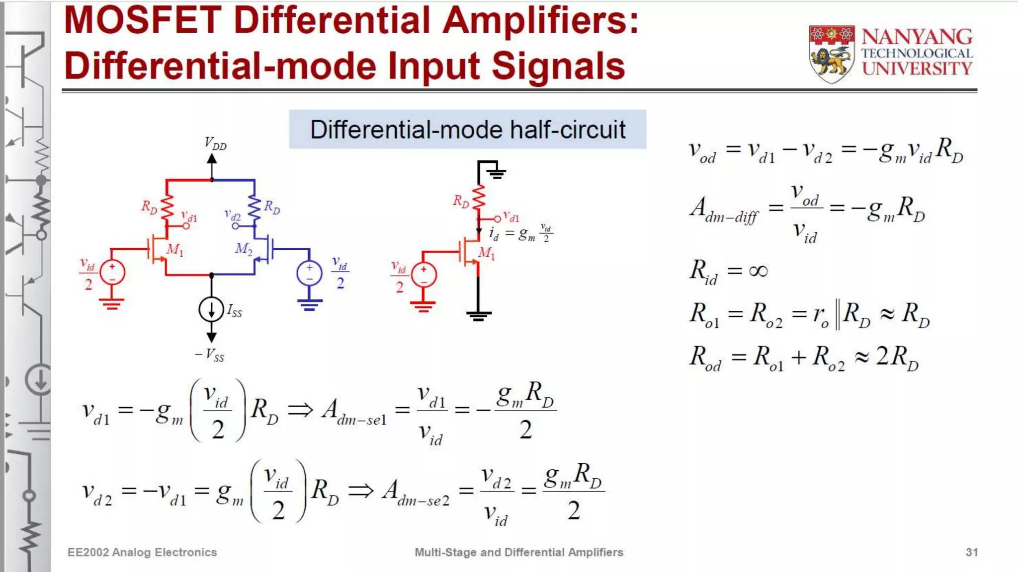
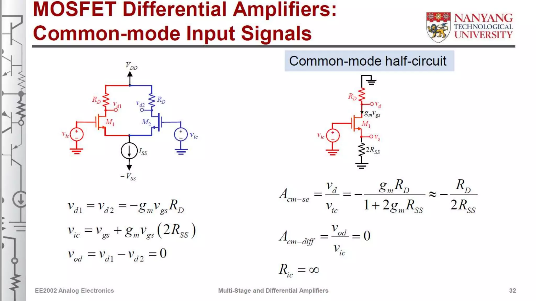
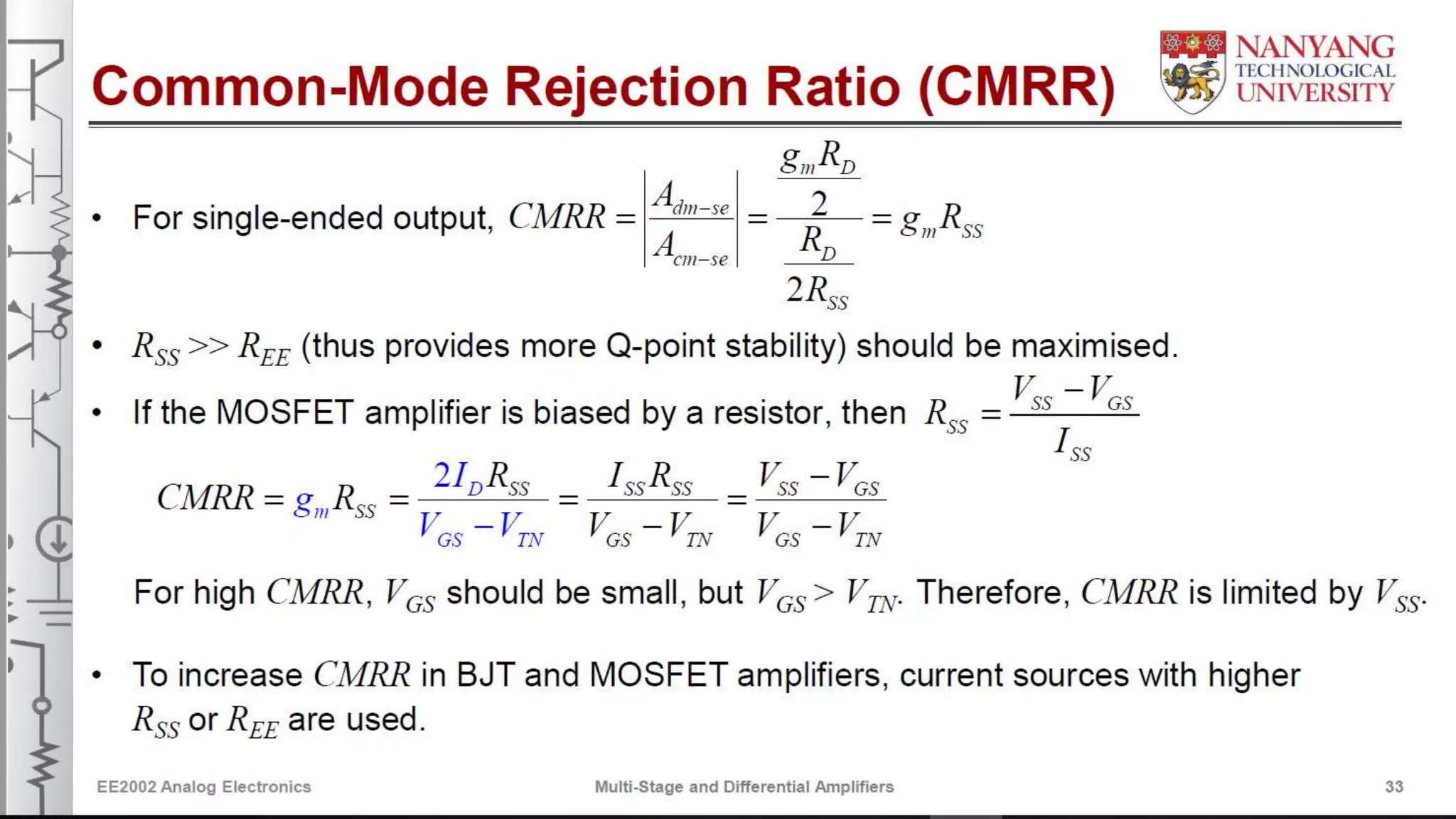
Part 2.2
Multi-Stage and
Differential Amplifiers
Assoc Prof Zheng Yuanjin email: yjzheng@ntu.edu.sg
EE2002 Analog Electronics
References
Main Textbook:
Jaeger, Richard C. & Blalock, Travis N., “Microelectronic Circuit Design”,
4th Edition, McGraw-Hill, 2011 (Chapters 4, 5, 13, and 14)
Other References:
 Hambley, Allan R., “Electronics”, 2 Edition, Prentice Hall, 2000.nd
 Naemen, Donald A., “Electronic Circuit Analysis and Design”, 2 Edition,nd
McGraw-Hill, 2002
EE2002 Analog Electronics Multi-Stage and Differential Amplifiers 2
Lesson Objectives
At the end of this lesson, you should be able to:
• Perform DC analysis to determine Q-point of each transistor in multi-stage
AC-Coupled amplifiers
• Draw AC equivalent circuit for multi-stage AC-Coupled amplifiers
• Determine the voltage gain, input resistance and output resistance of multi-
stage AC-Coupled amplifiers
• Identify the circuit structure of differential amplifier
• Draw DC, differential-mode and common-mode half-circuits of differential
amplifier
EE2002 Analog Electronics Multi-Stage and Differential Amplifiers 3
Lesson Objectives
(Cont.)
• Calculate the Q-point of the transistors of differential amplifier
• Calculate differential-mode and common-mode gains, input and output
resistances, and CMRR with single-ended or differential output
• Perform similar analysis for current source biased differential amplifier
EE2002 Analog Electronics Multi-Stage and Differential Amplifiers 4
Outline
• Analysis of AC-coupled Multi-stage Amplifiers
- Voltage Gain
- Input Resistance
- Output Resistance
- Small Signal Limitations
• Three-stage AC-coupled Amplifiers
• DC and AC Properties of Differential Amplifiers
EE2002 Analog Electronics Multi-Stage and Differential Amplifiers 5
AC Coupled Amplifier:
An Example of a 3-Stage Amplifier
C-C
amplifier
V
CC
C-S amplifier C-E amplifier
R
D1 R1 RC2R
G1 R3
RI C   C3   C5
 
1 Q2
Q3
M1
C  
6
R
in
RG2 +C  
4
C  
2
+
-
R2vi
R4RE2 RE3
R
S1 v
oR
L
R
out
-
Provides high Rin
and moderate Av
Provides high Av Gives low
high gain stage from low
R and buffersout
RL
• Input and output of overall amplifier is AC-coupled through capacitors C and C .1 6
• Bypass capacitors C and C are used to get maximum voltage gain from the2 4
two inverting amplifiers.
EE2002 Analog Electronics Multi-Stage and Differential Amplifiers 6
AC Coupled Amplifier:
An Example of a 3-Stage Amplifier
AC-Coupled Amplifier:
DC Equivalent Circuit
C-C
amplifier
V
CC
C-S amplifier C-E amplifier
R
C2R1
R
D1
R3
RI C   C3   C  
5
1 Q2
Q3
M1
C  
6
RG1 +
C  
2
C  
4
+
-
R2vi
R4
R
S1 RE2 RE3
RL vo
-
Inter-stage coupling capacitors C and C transfer AC signals between amplifiers3 5
but provide isolation at DC, and prevent Q-points of Xtrs from being affected.
EE2002 Analog Electronics Multi-Stage and Differential Amplifiers 7
AC Coupled Amplifier:
DC Equivalent Circuit
AC-Coupled Amplifier:
Small-signal Equivalent Circuit
  V
CC
4
R R R R R RB2 1 2 B3 3
R
1 RC2
R
D1
R3
RI C  
3
C  
5
C  
1 Q2 Q3M1
C  
6
RinRG1
+
+
-
C  
2
C4
 
v
i R2 RE2
R
4
R
E3R
S1
vo
R
out
R
L
-
+ v -R
I
B3 3 E3G1 D1 B2 C2
++ + r
p3
g v g v
m2 2
m1 1
r
o1
R
out+
-
vi v2 rp2
g v
m3 3
vo
-
Rin
R v
1
R
B2 RE3 R
L
G1 RD1
ro2 RC2 RB3
ro3
- - C3S1 E2
R  R RR  R R I 2 C2 B3I1 D1 B2
EE2002 Analog Electronics Multi-Stage and Differential Amplifiers 8
AC Coupled Amplifier:
Small-signal Equivalent Circuit
AC-Coupled Amplifier:
Output Resistance
+ v -R
I
B3 3G1 D1 B2 C2 E3
++ + r
p3
g v g vm1 1 m2 2
+
-
R
out
R
L
vi v2 rp2 vo
-
RG1 v1
R
E3ro1 RI1
r
o2 RI2 g v
m3 3
ro3
- - C3S1 E2
R  R R R  R R
I 2 C2 B3
I1 D1 B2
r  r Rp 3 o2 I 2
r  r R  r  r R
 p3 o2
I 2 r R p
3
o2 I 2
Rout   1 o3 E3  1  33
EE2002 Analog Electronics Multi-Stage and Differential Amplifiers 11
AC Coupled Amplifier:
Output Resistance
AC-Coupled Amplifier in General
v
N
R
I
v1 v2 v3
+
Stage
1
Stage
2
Stage v
o+
-
RLvi
R
in2Rin
N -R
outRout(N-1)
To find RoutTo find Rin To find Avt(i)
v
i+1
i
xix vi
Stage StageStage
1
+
-
+
-
v
x
v
x
R
in(i+1)
iRin2 Rout(N-1)
N
EE2002 Analog Electronics Multi-Stage and Differential Amplifiers 14
Differential Amplifiers
Piezoelectric Transducers
Strain GaugeCase
Epoxy
plotting
Backing
material
Electrodes
Piezoelectric
element
Thermal Couple
Thermocouple Lead
wire
Gage
A+
Vout
B
Target
surface
Ice bath
(known constant
temperature for
reference)
Reference
junctions
Ref.
EE2002 Analog Electronics Multi-Stage and Differential Amplifiers 15
Differential Amplifiers
V
CC
V
DD
RC vC1
Q1
RC
R
DRD
v
C2 vD1
v
D2
Q2 M1 M2
+
-
v1v1
+
- v2
+
-
+
-
v
2
R
EE R
SS
- VEE -VSS
• Differential amplifier forms the heart of operational amplifier.
• It contains two transistors in symmetrical configuration.
• It has two inputs and two outputs.
• Ideal differential amplifier uses perfectly matched transistors.
EE2002 Analog Electronics Multi-Stage and Differential Amplifiers 16
Common-mode Rejection Ratio (CMRR)
• Measures ability of amplifier to amplify desired differential-mode input signal
and reject undesired common-mode input signal.
• For differential output, since A = 0, CMRR = .cm-diff
• For single-ended output,
g Rm CA
dm-se 2CMRR    g R
R m EE
A Ccm-se
2REE
EE2002 Analog Electronics Multi-Stage and Differential Amplifiers 23
Bipolar Common-mode Half-Circuits
+VCC +VCC
+VCC +VCC
RC RC RC
R
C
R
C v
c1vC1 vC1v
C1 vC2
Q
1
Q
2
vev
IC vicvE
2REE
v
IC vIC 2REE
2R
EE
-VEE
(b) (c)2REE 2REE (a)
Q-point analysis
with no DC input
Large DC common-
mode input
Common-mode
signal analysis-VEE -VEE
All points on line of symmetry become open circuits.
• DC circuit with V set to zero is used to find amplifier’s Q-point.IC
• Half circuit (c) is used for common-mode signal analysis and represents
the C-E amplifier with emitter resistor 2R .EE
EE2002 Analog Electronics Multi-Stage and Differential Amplifiers 27
Biasing with Electronic Current Sources
• Differential amplifiers are biased using electronicV
CC
current sources to stabilise the operating pointRC RC
v
C1 vC2
and increase effective value of R to improveQ2 EEQ1
CMRR.v1
+
-
+
- v2
I
EE
- VEE
• Electronic current source has a DC current equal
to I (or I ) and an output resistance equal toV
DD
EE SS
R (or R ).EE SSRD RD
v
D2
v
D1
M1 M2
• DC model of the electronic current source is a
DC current source, I (or I ) while AC model isv1
+
-
+
v2
- EE SSI
SS
a resistance R (or R ).EE SS-VSS
EE2002 Analog Electronics Multi-Stage and Differential Amplifiers 28
Multi-Stage and
Differential Amplifiers
-End of Lecture-

16 s1 ee2002_ld_multi-stage_differential_amplifiers_v1.3 (powerpoint version)

  • 1.
    Part 2.2 Multi-Stage and DifferentialAmplifiers Assoc Prof Zheng Yuanjin email: yjzheng@ntu.edu.sg EE2002 Analog Electronics
  • 2.
    References Main Textbook: Jaeger, RichardC. & Blalock, Travis N., “Microelectronic Circuit Design”, 4th Edition, McGraw-Hill, 2011 (Chapters 4, 5, 13, and 14) Other References:  Hambley, Allan R., “Electronics”, 2 Edition, Prentice Hall, 2000.nd  Naemen, Donald A., “Electronic Circuit Analysis and Design”, 2 Edition,nd McGraw-Hill, 2002 EE2002 Analog Electronics Multi-Stage and Differential Amplifiers 2
  • 3.
    Lesson Objectives At theend of this lesson, you should be able to: • Perform DC analysis to determine Q-point of each transistor in multi-stage AC-Coupled amplifiers • Draw AC equivalent circuit for multi-stage AC-Coupled amplifiers • Determine the voltage gain, input resistance and output resistance of multi- stage AC-Coupled amplifiers • Identify the circuit structure of differential amplifier • Draw DC, differential-mode and common-mode half-circuits of differential amplifier EE2002 Analog Electronics Multi-Stage and Differential Amplifiers 3
  • 4.
    Lesson Objectives (Cont.) • Calculatethe Q-point of the transistors of differential amplifier • Calculate differential-mode and common-mode gains, input and output resistances, and CMRR with single-ended or differential output • Perform similar analysis for current source biased differential amplifier EE2002 Analog Electronics Multi-Stage and Differential Amplifiers 4
  • 5.
    Outline • Analysis ofAC-coupled Multi-stage Amplifiers - Voltage Gain - Input Resistance - Output Resistance - Small Signal Limitations • Three-stage AC-coupled Amplifiers • DC and AC Properties of Differential Amplifiers EE2002 Analog Electronics Multi-Stage and Differential Amplifiers 5
  • 6.
    AC Coupled Amplifier: AnExample of a 3-Stage Amplifier C-C amplifier V CC C-S amplifier C-E amplifier R D1 R1 RC2R G1 R3 RI C   C3   C5   1 Q2 Q3 M1 C   6 R in RG2 +C   4 C   2 + - R2vi R4RE2 RE3 R S1 v oR L R out - Provides high Rin and moderate Av Provides high Av Gives low high gain stage from low R and buffersout RL • Input and output of overall amplifier is AC-coupled through capacitors C and C .1 6 • Bypass capacitors C and C are used to get maximum voltage gain from the2 4 two inverting amplifiers. EE2002 Analog Electronics Multi-Stage and Differential Amplifiers 6 AC Coupled Amplifier: An Example of a 3-Stage Amplifier
  • 7.
    AC-Coupled Amplifier: DC EquivalentCircuit C-C amplifier V CC C-S amplifier C-E amplifier R C2R1 R D1 R3 RI C   C3   C   5 1 Q2 Q3 M1 C   6 RG1 + C   2 C   4 + - R2vi R4 R S1 RE2 RE3 RL vo - Inter-stage coupling capacitors C and C transfer AC signals between amplifiers3 5 but provide isolation at DC, and prevent Q-points of Xtrs from being affected. EE2002 Analog Electronics Multi-Stage and Differential Amplifiers 7 AC Coupled Amplifier: DC Equivalent Circuit
  • 8.
    AC-Coupled Amplifier: Small-signal EquivalentCircuit   V CC 4 R R R R R RB2 1 2 B3 3 R 1 RC2 R D1 R3 RI C   3 C   5 C   1 Q2 Q3M1 C   6 RinRG1 + + - C   2 C4   v i R2 RE2 R 4 R E3R S1 vo R out R L - + v -R I B3 3 E3G1 D1 B2 C2 ++ + r p3 g v g v m2 2 m1 1 r o1 R out+ - vi v2 rp2 g v m3 3 vo - Rin R v 1 R B2 RE3 R L G1 RD1 ro2 RC2 RB3 ro3 - - C3S1 E2 R  R RR  R R I 2 C2 B3I1 D1 B2 EE2002 Analog Electronics Multi-Stage and Differential Amplifiers 8 AC Coupled Amplifier: Small-signal Equivalent Circuit
  • 11.
    AC-Coupled Amplifier: Output Resistance +v -R I B3 3G1 D1 B2 C2 E3 ++ + r p3 g v g vm1 1 m2 2 + - R out R L vi v2 rp2 vo - RG1 v1 R E3ro1 RI1 r o2 RI2 g v m3 3 ro3 - - C3S1 E2 R  R R R  R R I 2 C2 B3 I1 D1 B2 r  r Rp 3 o2 I 2 r  r R  r  r R  p3 o2 I 2 r R p 3 o2 I 2 Rout   1 o3 E3  1  33 EE2002 Analog Electronics Multi-Stage and Differential Amplifiers 11 AC Coupled Amplifier: Output Resistance
  • 14.
    AC-Coupled Amplifier inGeneral v N R I v1 v2 v3 + Stage 1 Stage 2 Stage v o+ - RLvi R in2Rin N -R outRout(N-1) To find RoutTo find Rin To find Avt(i) v i+1 i xix vi Stage StageStage 1 + - + - v x v x R in(i+1) iRin2 Rout(N-1) N EE2002 Analog Electronics Multi-Stage and Differential Amplifiers 14
  • 15.
    Differential Amplifiers Piezoelectric Transducers StrainGaugeCase Epoxy plotting Backing material Electrodes Piezoelectric element Thermal Couple Thermocouple Lead wire Gage A+ Vout B Target surface Ice bath (known constant temperature for reference) Reference junctions Ref. EE2002 Analog Electronics Multi-Stage and Differential Amplifiers 15
  • 16.
    Differential Amplifiers V CC V DD RC vC1 Q1 RC R DRD v C2vD1 v D2 Q2 M1 M2 + - v1v1 + - v2 + - + - v 2 R EE R SS - VEE -VSS • Differential amplifier forms the heart of operational amplifier. • It contains two transistors in symmetrical configuration. • It has two inputs and two outputs. • Ideal differential amplifier uses perfectly matched transistors. EE2002 Analog Electronics Multi-Stage and Differential Amplifiers 16
  • 23.
    Common-mode Rejection Ratio(CMRR) • Measures ability of amplifier to amplify desired differential-mode input signal and reject undesired common-mode input signal. • For differential output, since A = 0, CMRR = .cm-diff • For single-ended output, g Rm CA dm-se 2CMRR    g R R m EE A Ccm-se 2REE EE2002 Analog Electronics Multi-Stage and Differential Amplifiers 23
  • 27.
    Bipolar Common-mode Half-Circuits +VCC+VCC +VCC +VCC RC RC RC R C R C v c1vC1 vC1v C1 vC2 Q 1 Q 2 vev IC vicvE 2REE v IC vIC 2REE 2R EE -VEE (b) (c)2REE 2REE (a) Q-point analysis with no DC input Large DC common- mode input Common-mode signal analysis-VEE -VEE All points on line of symmetry become open circuits. • DC circuit with V set to zero is used to find amplifier’s Q-point.IC • Half circuit (c) is used for common-mode signal analysis and represents the C-E amplifier with emitter resistor 2R .EE EE2002 Analog Electronics Multi-Stage and Differential Amplifiers 27
  • 28.
    Biasing with ElectronicCurrent Sources • Differential amplifiers are biased using electronicV CC current sources to stabilise the operating pointRC RC v C1 vC2 and increase effective value of R to improveQ2 EEQ1 CMRR.v1 + - + - v2 I EE - VEE • Electronic current source has a DC current equal to I (or I ) and an output resistance equal toV DD EE SS R (or R ).EE SSRD RD v D2 v D1 M1 M2 • DC model of the electronic current source is a DC current source, I (or I ) while AC model isv1 + - + v2 - EE SSI SS a resistance R (or R ).EE SS-VSS EE2002 Analog Electronics Multi-Stage and Differential Amplifiers 28
  • 34.