Right-hand
thread
Thread that willassemble when
turned clockwise.
Left-hand
thread
Thread that will assemble when
turned counter-clockwise.
THREAD TERMINOLOGY
Turnbuckle use RH and LH thread at
each end to double displacement.
11.
Crest
Root
Thread angle
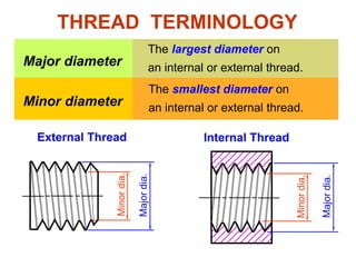
THREAD TERMINOLOGY
Thepeak edge of a thread.
The bottom of the thread cut into
a cylindrical body.
The angle between threads faces.
Internal Thread
External Thread
Crest
Root
Thread angle
Crest
Root
12.
Major diameter
The largestdiameter on
an internal or external thread.
Minor diameter
The smallest diameter on
an internal or external thread.
Internal Thread
External Thread
Minor
dia.
Major
dia.
THREAD TERMINOLOGY
Minor
dia.
Major
dia.
13.
Pitch
The distance betweencrests of
threads.
Lead The distance a screw will advance
when turned 360o.
THREAD TERMINOLOGY
Internal Thread
External Thread
Pitch
Pitch
14.
Form is theprofile shape of the
thread.
Thread Form
THREAD TERMINOLOGY
Example :
“knuckle thread form”
External thread Internalthread
DETAILED REPRESENTATION
60o
Pitch
Use slanting lines to represent crest and root.
Roots and crest are drawn in sharp Vs.
Thread runout
21.
SCHEMATIC REPRESENTATION
External thread
PitchCrest (thin line)
Root (thick line)
Use alternate long and short lines for representing
crests and roots of the thread, respectively.
Internal thread
22.
SIMPLIFIED REPRESENTATION
External threadInternal thread
Use thick continuous lines for representing crest
and thin continuous lines for representing root of
the thread, respectively.
Pitch/2
Root
Crest
Thread runout
23.
SIMPLIFIED REPRESENTATION
External threadInternal thread
Sectional view
Use thick continuous lines for representing crest
and thin continuous lines for representing root of
the thread, respectively.
Nominal
size
Major
diameter
Pitch Minor
diameter
Tap drillsize
M6 6.00 1.00 4.92 5.00
M8 8.00 1.25 6.65 6.75
M10 10.00 1.50 8.38 8.50
M12 12.00 1.75 10.11 10.00
METRIC COARSE THREAD
Minor diameter = Major diameter – Pitch
Minor diameter ≈ Tap drill size
[Table 9.1]
Metric thread
In thread drawing, the following relationship is used.
26.
Nominal
size
Major
diameter
Pitch Minor
diameter
Tap drillsize
M8 8.00
0.75 7.188 7.25
1.00 6.917 7.00
M10 10.00
0.75 9.188 9.25
1.00 8.917 9.00
1.25 8.647 8.75
METRIC FINE THREAD
[Table 9.2]
Minor diameter = Major diameter – Pitch
Minor diameter ≈ Tap drill size
In thread drawing, the following relationship is used.
27.
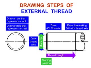
Thread Length
DRAWING STEPSOF
EXTERNAL THREAD
Starting
position
Draw
thread
axis
Major
dia.
Minor
dia.
Draw
45o Chamfer
Draw line making
30o with thread axis
Draw a circle that
represents a crest.
Draw an arc that
represents a root.
28.
Internal Thread
1. Throughthreaded hole
DRAWING STEPS OF
THREADED HOLE
Draw
thread
axis
Major
dia.
Minor
dia.
Draw a root
Draw a crest
Sectional view
Draw a circle that
represents a crest.
Draw an arc that
represents a root.
root
crest
Section lines are drawn
into the crest of a thread.
29.
Minor
dia.
DRAWING STEPS OF
THREADEDHOLE
2. Blinded threaded hole
Draw
thread
axis
Major
dia.
Hole depth
Thread depth
Draw a circle that
represents a crest.
Draw an arc that
represents a root.
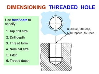
DIMENSIONING EXTERNAL THREAD
M10×1.5
×1.0 Fine thread
Coarse thread
xx
Thread
length
Use local note to specify :- thread form, nominal size,
pitch (if it is a fine thread)
Use typical method to specify :- thread length.
32.
3. Thread form
4.Nominal size
5. Pitch
1. Tap drill size
2. Drill depth
6. Thread depth
8.50 Drill, 20 Deep,
M10 Tapped, 15 Deep
DIMENSIONING THREADED HOLE
Use local note to
specify
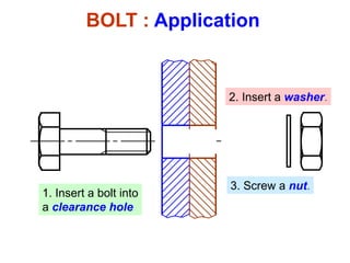
BOLT : Terminology
Boltis a threaded cylinder with a head.
Hexagonal head
bolt and nut
Head
thickness
Thread length
Length
Width
across flat
Dimensions of bolt’s head are
listed in table 9.4.
35.
Draw
bolt
axis
Draw an
end view
ofthe head
B
Starting
position
H
Draw a
bolt head
B/2 B/2
30o
Length
Thread Length
Major
f
Draw
body of a bolt
BOLT : Drawing steps
36.
NUT : Drawingsteps
Draw an end view
of the nut
B
H
B/2 B/2
Dimensions of the nut are given in Table 9.14.
Dash lines represent
a threaded hole are
omitted for clarity.
37.
1. Insert abolt into
a clearance hole
2. Insert a washer.
3. Screw a nut.
BOLT : Application
38.
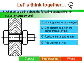
Let’ s thinktogether…
What do you think about the following suggestions for
design improvement?
(B) Use shorter bolt with the
same thread length.
Correct
(C) Reduce the thread length.
Inappropriate Wrong
(D) Add washer or nut.
(A) Nothing have to be changed.
39.
Let’ s thinktogether…
What do you think about the following suggestions for
design improvement?
(B) Use a bolt of this length but
has a longer thread length.
(C) Use a longer bolt with the
same thread length.
(D) Add washer.
(A) Nothing have to be changed.
Correct Inappropriate Wrong
40.
Let’ s thinktogether…
What do you think about the following suggestions for
design improvement ?
(B) Use a bolt of this length but
has a shorter thread length.
(C) Use a longer bolt with the
same thread length.
(D) Add washer.
(A) Nothing have to be changed.
Correct Inappropriate Wrong
41.
Let’ s thinktogether…
What do you think about the following suggestions for
design improvement?
(A) Use a bolt of this length but
has a shorter thread length.
(B) Use a longer bolt with the
same thread length.
(C) Use a longer bolt by
increasing a thread length
(D) Remove washer.
Correct Inappropriate Wrong
42.
Let’ s thinktogether…
What do you think about the following suggestions for
design improvement ?
(A) Increase the bolt diameter.
(B) Use washer with larger
outside diameter.
(C) Reduce the hole diameter.
(D) Add washer at bolt head.
Correct Inappropriate Wrong
43.
Let’ s thinktogether…
What do you think about the following suggestions for
design improvement ?
(B) Use a bolt with shorter
thread length.
(C) Add washer.
(D) Increase drill and thread
depths.
(A) Nothing have to be changed.
Correct Inappropriate Wrong
44.
Let’ s thinktogether…
What do you think about the following suggestions for
design improvement ?
(A) Nothing have to be changed.
(B) Use a bolt with slightly
longer thread length.
Correct Inappropriate Wrong
45.
Stud is aheadless bolt, threaded at both ends.
STUD : Terminology
Thread length
Length
Thread length
Drawing
representation
46.
Major
f
STUD : Drawingsteps
Draw
stud
axis
Minor
f
Starting
position
Stud Length
Thread Length Thread Length
Draw
45o Chamfer
Draw
45o Chamfer
Draw line making
30o with axis
47.
STUD : Application
1.Drill a hole.
3. Screw a stud.
4. Place the part to be
fastened.
5. Insert washer and
fastened a nut.
2. Tap a hole.
48.
Let’ s thinktogether…
What is the mistake in the following use of stud ?
49.
Let’ s thinktogether…
What is the mistake in the following use of stud ?
50.
Cap screw issimilar to bolt, but has a longer thread
than a bolt.
CAP SCREW : Terminology
51.
CAP SCREW :Counterbore hole
x drill,
fy C’bore,
z deep
x drill,w deep,
f y C’bore,
z deep
z
52.
x drill,
CSK tofy
CAP SCREW : Countersink hole
x drill, w deep,
CSK to fy
y
Draw 90o
53.
SET SCREW :Terminology
Set screw is a threaded cylinder used to prevent
rotation or movement between parts.


![Nominal
size
Major
diameter
Pitch Minor
diameter
Tap drill size
M6 6.00 1.00 4.92 5.00
M8 8.00 1.25 6.65 6.75
M10 10.00 1.50 8.38 8.50
M12 12.00 1.75 10.11 10.00
METRIC COARSE THREAD
Minor diameter = Major diameter – Pitch
Minor diameter ≈ Tap drill size
[Table 9.1]
Metric thread
In thread drawing, the following relationship is used.](https://image.slidesharecdn.com/1-180816063512-ef43c4/85/1-3-thread-fastener-25-320.jpg)
![Nominal
size
Major
diameter
Pitch Minor
diameter
Tap drill size
M8 8.00
0.75 7.188 7.25
1.00 6.917 7.00
M10 10.00
0.75 9.188 9.25
1.00 8.917 9.00
1.25 8.647 8.75
METRIC FINE THREAD
[Table 9.2]
Minor diameter = Major diameter – Pitch
Minor diameter ≈ Tap drill size
In thread drawing, the following relationship is used.](https://image.slidesharecdn.com/1-180816063512-ef43c4/85/1-3-thread-fastener-26-320.jpg)