
Recommended
More Related Content
What's hot
What's hot (20)
Similar to Three phase power measurement
Similar to Three phase power measurement (20)
More from Jayaraju Gaddala
Recently uploaded
Recently uploaded (20)
Three phase power measurement
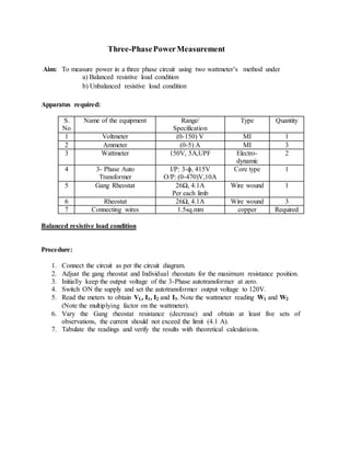
- 1. Three-PhasePowerMeasurement Aim: To measure power in a three phase circuit using two wattmeter’s method under a) Balanced resistive load condition b) Unbalanced resistive load condition Apparatus required: S. No Name of the equipment Range/ Specification Type Quantity 1 Voltmeter (0-150) V MI 1 2 Ammeter (0-5) A MI 3 3 Wattmeter 150V, 5A,UPF Electro- dynamic 2 4 3- Phase Auto Transformer I/P: 3-ɸ, 415V O/P: (0-470)V,10A Core type 1 5 Gang Rheostat 26Ω, 4.1A Per each limb Wire wound 1 6 Rheostat 26Ω, 4.1A Wire wound 3 7 Connecting wires 1.5sq.mm copper Required Balanced resistive load condition Procedure: 1. Connect the circuit as per the circuit diagram. 2. Adjust the gang rheostat and Individual rheostats for the maximum resistance position. 3. Initially keep the output voltage of the 3-Phase autotransformer at zero. 4. Switch ON the supply and set the autotransformer output voltage to 120V. 5. Read the meters to obtain VL, I1, I2 and I3. Note the wattmeter reading W1 and W2 (Note the multiplying factor on the wattmeter). 6. Vary the Gang rheostat resistance (decrease) and obtain at least five sets of observations, the current should not exceed the limit (4.1 A). 7. Tabulate the readings and verify the results with theoretical calculations.
- 3. Observation table -1 Three phase power in a balanced load Theoretical calculations: For Star connected Balanced load: VPh= VL / √3 IPh=IL W1=√3 VPh IPh Cos (30 + Φ) (OR) VL .IL Cos (30 + Φ) W2=√3 VPh IPh Cos (30 - Φ) (OR) VL .IL Cos (30 - Φ) W1+ W2= √3 VL .IL Cos Φ Calculated power WC= VPh IPh1+ VPh IPh2+ VPh IPh3 Determination of power factor for the balanced load ∅ = 𝑇𝑎𝑛−1 (√3. (𝑊2−𝑊1) (𝑊2+𝑊1) )
- 4. Unbalanced resistive load Procedure: 1. Connect the circuit as per circuit diagram in Fig. 2. 2. Adjust the three rheostats and gang rheostat at the maximum resistance position. 3. Switch ON the supply and set the autotransformer output voltage to120V. 4. Take five sets of observation for different rheostat settings such that the reading of I1, I2 and I3 in each set is appreciably different to create unbalanced loading condition. (Don’t vary the gang rheostat).The current should not exceed the limits in each arm. 5. Note down I1, I2, I3, V1, V2, V3, W1 and W2. Check the result by completing the computations indicated in Table.2.
- 6. Observation table -2 (three phase power in an unbalanced load) Theoretical calculations: For Star connected Unbalanced load: Precautions: 1. All the connections should be tight. 2. Initially keep the output voltage of the autotransformer to zero. Result: