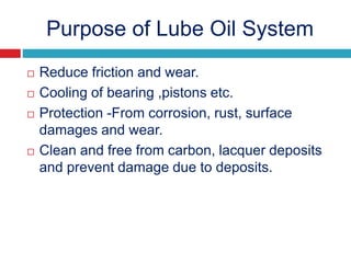
The document provides information about the components, purpose, and operation of a lube oil system for diesel engines. It includes:
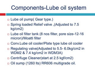
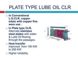
- A list of the main components of the lube oil system such as the lube oil pump, filter, cooler, sump, and their purposes.
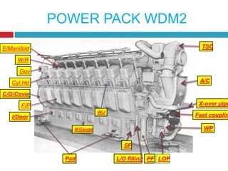
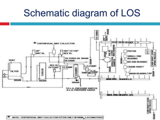
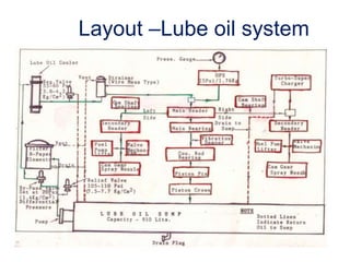
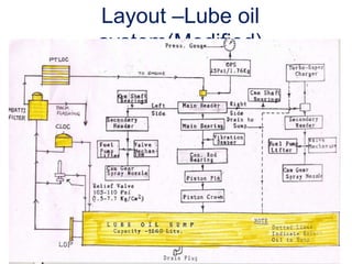
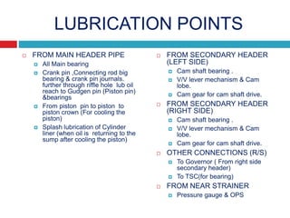
- Schematic diagrams that illustrate the layout and flow of oil through the system to lubricate parts like the main bearings, connecting rod bearings, camshaft, and more.
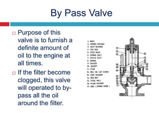
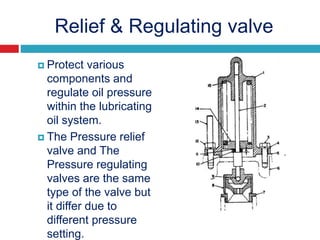
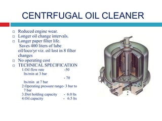
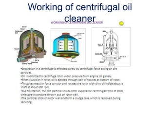
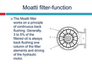
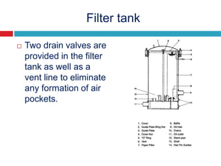
- Descriptions of additional components like the relief and regulating valves that control oil pressure, and the centrifugal cleaner and filter that remove contaminants from the oil.
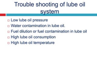
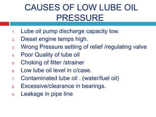
- Troubleshooting guidance for issues involving low oil pressure,


![Lubrication in ice. ppt 4 [autosaved]](https://cdn.slidesharecdn.com/ss_thumbnails/lubricationinice-210526071608-thumbnail.jpg?width=640&height=640&fit=bounds)