This document provides specifications for MCC 1N4728 through 1N4764 zener diodes. It includes maximum ratings, electrical characteristics, and dimensions for the glass packaged diodes. Key specifications include:
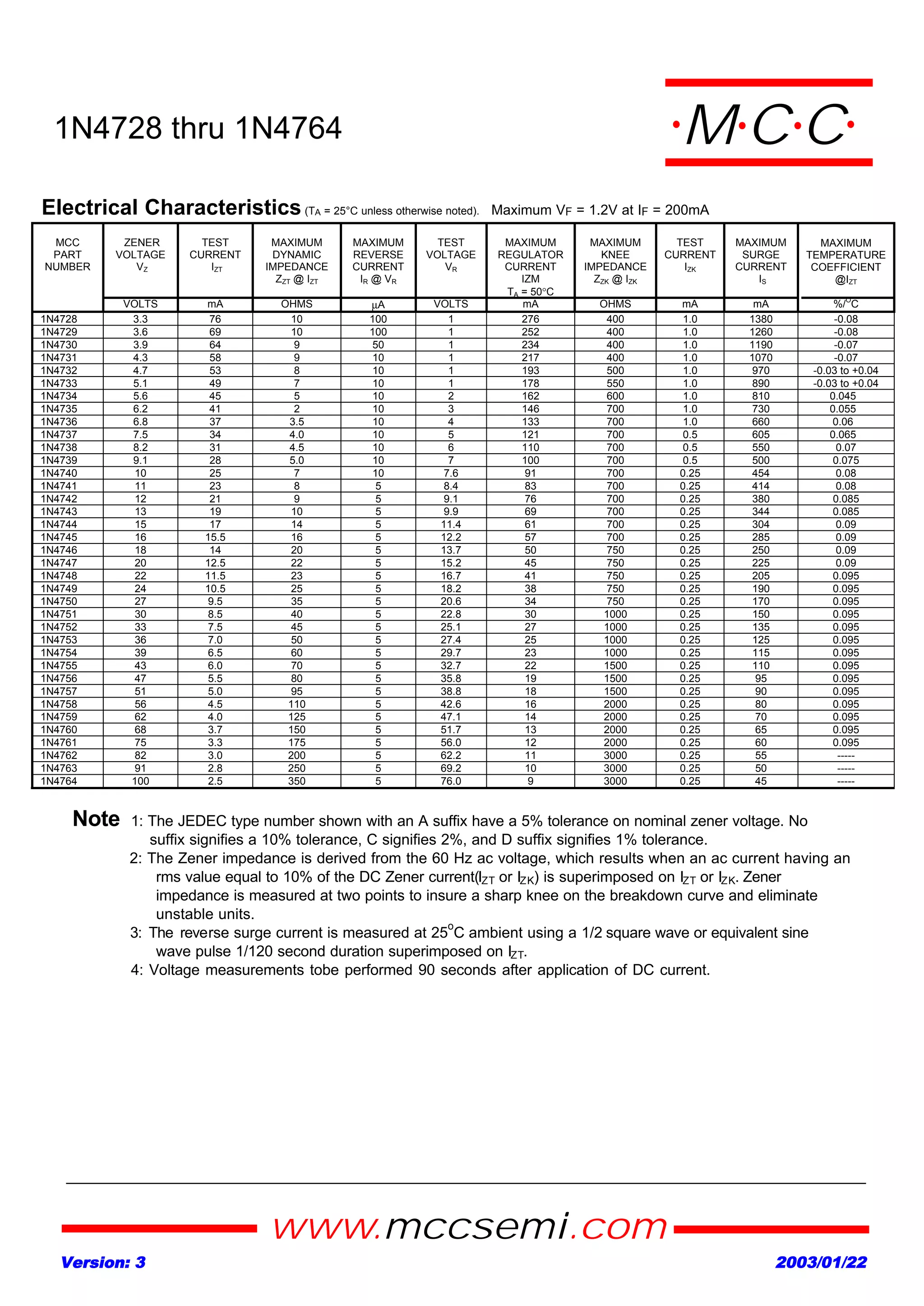
- Voltage ratings from 3.3V to 100V
- Power dissipation of 1W at 100C case temperature
- Test currents and voltages, dynamic impedance, reverse leakage, and more
- Temperature coefficients and maximum surge currents
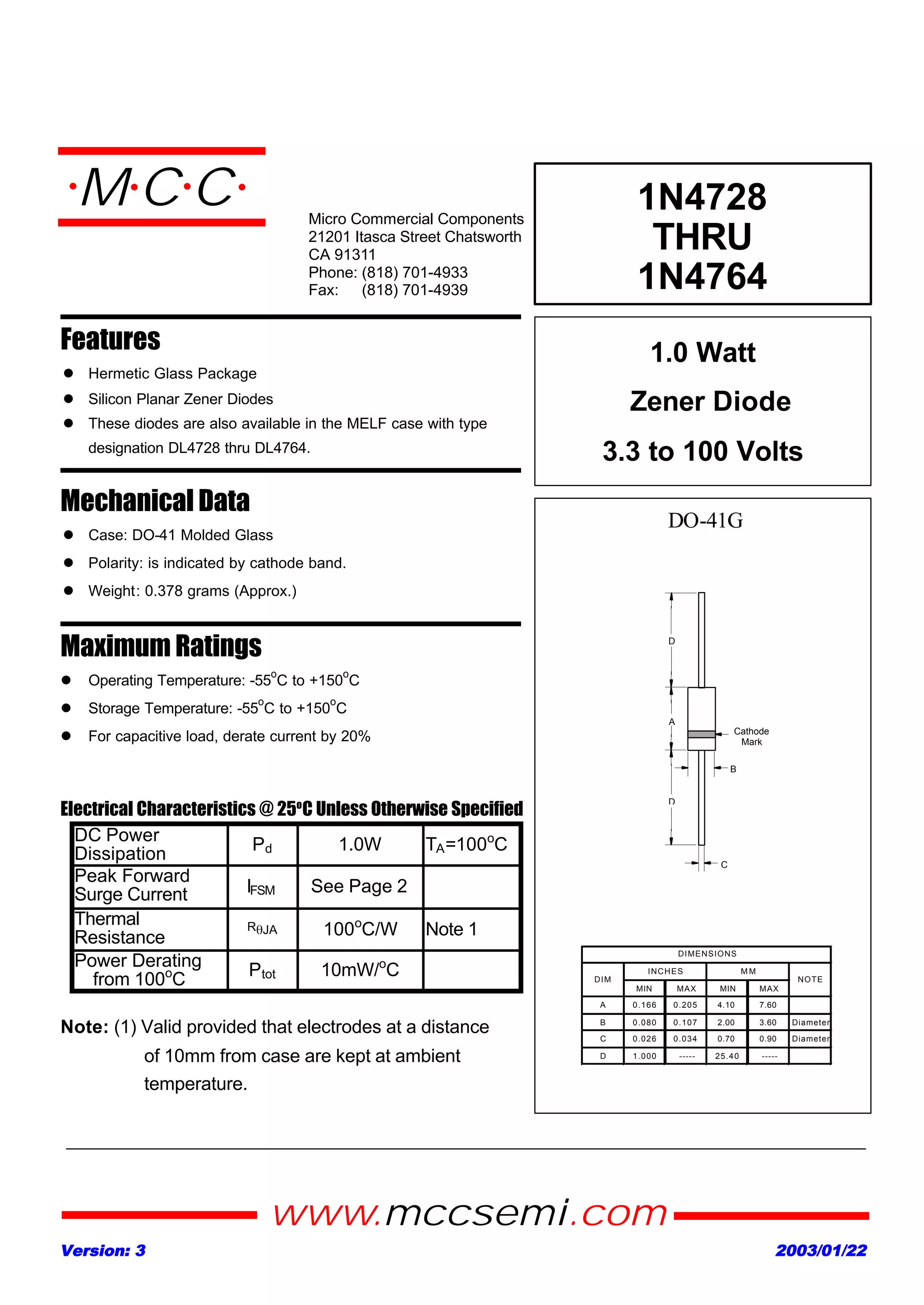
- Hermetic glass packages in DO-41 case from 0.166 to 0.205 inches in length