Download to read offline
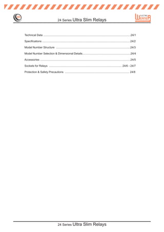
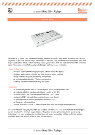
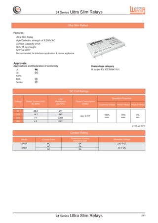
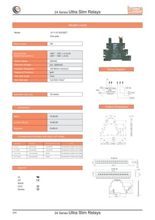

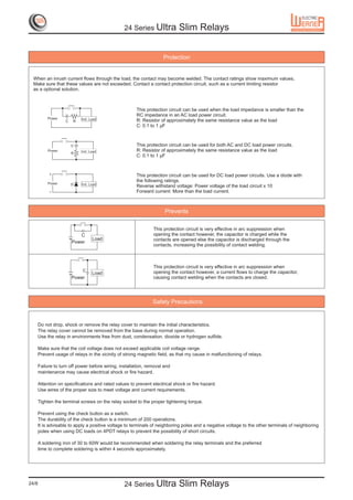

The document outlines the specifications and features of Werner's 24 series ultra slim relays, designed for compact and high-performance applications. These relays are fully sealed, suitable for various voltages, and feature a dielectric strength of up to 5000V, making them ideal for low current circuits while minimizing space and heat production. It includes detailed information on model selection, installation accessories, and safety precautions to ensure optimal usage.