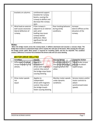
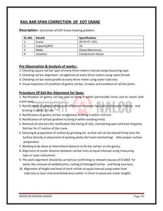
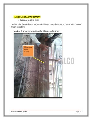
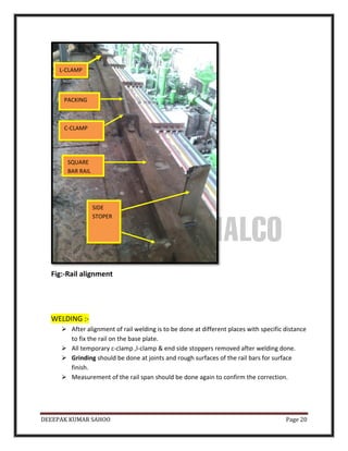
DEEEPAK KUMAR SAHOO Page 1
SUBMITTED TO
NALCO(M&R),DAMANJODI
SUBMITTEDBY
Mr.DEEPAKKUMARSAHOO
YEAR-2015-2016
DEEEPAK KUMAR SAHOO Page 2
DIAGNOSIS & RECTIFICATION OF BRIDGE (EOT) CRANES
TRACKING PROBLEMS
Introduction
Poor bridge tracking can be a major and expensive maintenance problem for
overhead cranes. It is also one of the most critical problems to troubleshoot.
Tracking problems are difficult to diagnose because of the many conditions that
cause them. If they are not pro-actively rectified, the destructive action feeds on
itself and problems can multiply. When this happens, the problem becomes even
more complicated.
Symptoms
For abnormal tracking behavior, the following are some of the symptoms:
 Frequent replacement of wheels, wheel bearings, and rails.
 Broken tie‐backs between runway beams and columns.
 Extra drive power required to muscle through certain areas of the runway.
 Broken wheel flanges.
 Loud scraping sounds.
 Wheel flanges pressed hard against the rail head.
 End trucks cracked near the wheel assemblies.
 Loose girder connections.
 Wheel flanges attempt to climb over the rail then suddenly crash down.
 Bridge derailment.
Skewing, side thrust, and wheel/rail wear occur naturally during bridge tracking.
Design specifications for cranes and runways provide for lateral crane loads and
forces caused by steering and skewing.
DEEEPAK KUMAR SAHOO Page 3
A Simplified Description of Skewing
Skewing occurs when there is a difference in traction or speed between the driven ends of the
bridge. For this description we will assume that skewing is initiated by one drive end moving
faster than the other, or from drive wheel skidding/slippage.
Wheel float
Figure 1:-Crane wheel floating
DEEEPAK KUMAR SAHOO Page 4
When this happens, the following events are set into motion:
I. The drive effectively delivers a larger traction force to one end of the bridge.
II. The difference in traction between the driven ends causes the bridge span to act as a
lever arm.
III. The lever arm forces are resisted by lateral loading of the wheels and rail.
IV. The lever‐arm action causes the bridge frame to temporarily deform
V. The deformation causes the corners of the bridge frame to twist, and the wheels to
VI. become temporarily misaligned. If the frame is not stiff enough, the misalignment will
contribute to the tracking problem.
VII. The frame will remain deformed as long as there is a difference in traction force
between the driven ends.
VIII. The traction difference causes the crane to steer to one side of the runway.
IX. The crane will continue to steer to one side until the wheel flange touches the side of
the rail head.
X. The wheel flange applies a lateral force to the runway.
XI. The lateral force creates a friction force parallel to the runway.
XII. The friction force counteracts the traction force.
XIII. The random differences of the friction forces between bridge ends causes the skew
angle to intermittently increase and decrease.
XIV. See Figure 2. The crane rotates (in plan) until the cumulative effect of wheel flange
contact and lateral friction are equal to the effect of the traction force difference
between the driven ends. The angle of rotation is the skew angle.
XV. If the skew angle is allowed to be large enough, the friction force parallel to the runway
will equal or exceed the traction force and the crane will bind and come to a halt.
XVI. If the drives have sufficient power and traction, the wheels will climb up the rail and the
crane may derail.
XVII. If the skew angle is prevented from being large, the flange will skip off the side of rail
and continue tracking along the runway path.
DEEEPAK KUMAR SAHOO Page 5
Six Troubleshooting Procedure for EOT crane Tracking Problems
Runway
Rail‐Related
Wheel‐Related
Bridge Frame
Alignment
Bridge
Mechanical‐Re
lated
Motor
Drive‐Related
Runway &
Building
Structure‐Relat
ed
DEEEPAK KUMAR SAHOO Page 6
RUNWAY RAIL RELATED
Condition Cause How to Detect Corrective Action
1 Runway rails out of
horizontal alignment.
Misaligned rails cause
wheels to bind.
Perform a runway
alignment survey
Align rails
2 Excessive wheel float
caused by rail wear.
float allows a larger
skew angle, larger
lateral rail force, and
binding.
Inspect sides of rail
head for excessive
wear.
Replace worn rails.
3 Excessive lateral rail
movement caused by
use of floating rail
clamps.
Floating clamps allow
rail to shift laterally,
causing a larger skew
angle.
Check for gaps
between rail base and
rail clamp. Clamps
should be tight against
both edges of rail
base.
Replace floating rail
clamps with
non‐floating type
clamps or clips.
4 Drive wheel skidding
or slippage.
Causes unbalanced
traction between drive
wheels resulting in
skewing.
Inspect rail surfaces
for liquid or debris.
Keep rails clean and
dry. Adjust motor
controls to reduce
acceleration.
5 Runway rail elevation
out of alignment.
Relatively large
elevation differences
are required to cause
problems.
Perform a runway
alignment survey.
Align rails per
tolerances.
RUNWAY & BUILDING STRUCTURE‐RELATED
Condition Cause How to Detect Corrective Action
1 Broken tie‐backs for
runway beams
Causes rail
misalignment
Visual structural
inspection.
replace tiebacks
with improved
design.
2 Long span runway
beam on one side of
the runway.
Longer beam spans
have larger deflection.
See note below
Observe poor tracking
behavior over bays
where one end of the
bridge is supported by
a beam with a
significantly
longer span than the
other end.
Specify positive
camber and increased
stiffness for the long
span beam.
3 Excessive deflection of
runway beam support
Columns are
eccentrically loaded by
Poor tracking at or
near columns
increase the
column stiffness
DEEEPAK KUMAR SAHOO Page 7
brackets on columns. cantilevered support
brackets for runway
beams, causing the
runway to deflect and
decrease the runway
span.
4 Wind load on exterior
wall causes excessive
lateral deflection of
runway.
If the runway is
adjacent to an exterior
wall, wind
loading may cause
runway lateral
deflection. More
significant for tall
structures.
Poor tracking behavior
during windy
conditions.
increase
lateral stiffness at the
elevation of the
runway.
Notes:
When the bridge travels across the runway beam, it deflects downward and assumes a concave shape. The
bridge then travels on a downward slope until it reaches the mid span of the beam. After passing the mid span,
the bridge travels uphill. More power is required for travelling uphill, and less for downhill. This condition
creates a difference in traction force between the driven ends and can cause skewing.
MOTOR DRIVE RELATED
Condition Causes How to Detect Corrective Action
1 Difference in braking
torque between drive
wheels.
Applies to
independent
drives with magnetic
control. One end of
the bridge stops faster
causing skewing.
Visual observation of
one end of the bridge
stopping before the
other.
Adjust brake torque
settings to obtain
equal torque.
2 Drive motor speeds
not
equal.
Applies to
independent
drives with magnetic
control. One end of
the bridge travels
faster causing skewing.
Monitor motor speeds
under dynamic
conditions
Service motors and/or
motor controls to
obtain
synchronized motor
speeds
DEEEPAK KUMAR SAHOO Page 8
BRIDGE MECHANICAL‐RELATED
Condition Causes How to Detect Corrective Action
1 Drive shaft too flexible Applies to cross‐shaft
connected drive
wheels. Flexible
shafting causes a
larger difference in
angular twist between
drive wheels.
Perform an
engineering
analysis to confirm
that angular deflection
of
shafting is within
allowable limits
Replace with larger
diameter shafting
for allowable shaft
twist.
2 Drive shaft couplings
loose or worn.
Causes drive wheels to
be unsynchronized.
Inspect bridge drive
couplings
Replace loose or worn
couplings.
3 Drive shafts become
preloaded,
shaft windup is
locked‐in.
Applies to cross‐shaft
connected drive
wheels where
4‐wheels are driven. If
one drive wheel slips
relative to the others,
the drive
shafts can become
preloaded with
torsion.
Observe tracking and
watch for wheel
skidding or slippage
Inspect rail surfaces
for liquid or debris.
Keep rails clean and
dry. Jack the drive
wheel off the rail to
release the torque.
BRIDGE FRAME ALIGNMENT
Condition Causes How to Detect Corrective Action
1 Bridge trucks, bogie
trucks, or end ties out
of alignment.
Original equipment
may be misaligned, or
became misaligned
from other causes.
Complete a precise
wheel alignment
survey.
"MCB" bearing
capsules can be
shimmed for
alignment.
2 Bridge span dimension
out of tolerance
relative
to runway rail span.
Has same effect as rail
span misalignment.
Use a precise laser
"distance meter" to
measure the bridge
wheel spans.
Consult with a
qualified person for
bridge span
modifications.
3 Loose girder
connections.
Allows bridge frame to
become misaligned.
Inspect girder
connections.
Complete a precise
wheel alignment
survey. Ream holes to
next larger bolt
diameter, use
interference fit bolts.
4 Bridge acceleration or
deceleration with
trolley at or near one
end of the bridge
One end of
bridge moves faster
than the other causing
skewing.
Observe tracking
behavior during
acceleration with
trolley at center of
Modify duty cycle so
that bridge
acceleration does
not start until trolley is
DEEEPAK KUMAR SAHOO Page 9
span compared to
acceleration with
trolley at end of
bridge.
near mid span of
bridge.
5 End trucks or end ties
too flexible.
Frame deformation
can cause temporary
wheel misalignment
and skewing.
Perform an
engineering analysis to
determine corner
rotation under normal
service loads.
Consult with a
qualified person to
increase the stiffness
of the bridge frame.
WHEEL RELATED
Condition Causes How to Detect Corrective Action
1 Wheel misalignment
relative to other
wheels and tracking
direction
Produces the same
effect as rail
misalignment, and
causes skewing.
Complete a precise
wheel alignment
survey.
"MCB" bearing
capsules can be
shimmed for
alignment.
2 Excessive wheel float
caused by wheel
flange wear.
Excessive float allows a
larger skew angle,
larger lateral rail
force, and binding.
Inspect wheel flanges
for excessive wear.
Use greater flange
hardness for
replacement wheels.
3 Drive wheel diameters
not matched within
tolerance.
Causes speed
difference across the
span, resulting
in skewing.
Check wheel tread
Diameters &
tolerances.
Replace drive wheels
with wheel pairs that
have matching
diameters within
recommended
tolerance.
4 Excessive wear of drive
wheel tread
Creates variable drive
tread circumference
and
causes a speed
difference between
drive wheels.
By visual examination.
Normal tread surfaces
should look perfectly
flat.
Replace worn wheels,
use greater tread
hardness
5 Excessive wheel float
due to tread profile
too wide for rail head.
Excessive float allows a
larger skew angle,
larger lateral rail
force, and binding.
Float should be within
the values shown
Replace with wheels
that have proper tread
width.
6 Wheel bearing failure. Causes skewing due to
rolling resistance at
one end of the bridge.
High local temperature
at the bearing capsule,
paint discoloration,
noise.
Replace bearing and
capsule.
DEEEPAK KUMAR SAHOO Page 10
Description:- Correction of EOT Crane tracking problem.
RAIL BAR SPAN CORRECTION OF EOT CRANE
SL.NO. Details Specification
1 Crane 28-HH-ET-1301
2 Capacity(MT) 10
3 Make Oswal Machinery
4 Location Compressor House
1. Checking square rail bar span at every three meters interval using measuring tape.
Pre Observation & Analysis of works:-
2. Checking rail bar alignment –straightness at every three meters using nylon thread.
3. Checking rail bar level-parallel at every three meter using water tube test.
4. Visual inspection of condition of gantry rail bar, its wear and condition of rail bar joints.
1. Rectification of gantry rail bar span to bring it within permissible limits and to match with
crane span.
Procedure Of Rail Bar Alignment for Span:
2. Rectification of gantry rail bar level difference between two rails at the same location and
to bring it within 10 mm.
3. Rectification of gantry rail bar straightness to bring it within ±10 mm.
4. Rectification of rail bar gradient to bring it within working limits.
5. Removal of rails bars for rectification like facing of rails, maintaining span and level of gantry
Rail bar for LT motion of the crane.
6. Cleaning & preparation of surface by grinding etc. so that rail can be placed firmly onto the
Surface directly or placement of packing plates (for level maintaining) after proper surface
preparation.
7. Welding to be done at intermittent distance to fix the rail bar on the gantry.
8. Alignment of center distance between rail bar lines at equal intervals using measuring
tape or Laser instrument.
9. The work alignment should be carried out confirming to relevant clauses of IS:3443 for
works like removal of welded joints, cutting of damaged rail bar and fixing new bars.
10. Alignment of height and level of each rail bar at equal interval using water level
tube test or laser instrument(tolerance within +/-5mm in every one meter length).
DEEEPAK KUMAR SAHOO Page 11
(Compressor & utility Area)
RAIL SPAN CORRECTION OF EOT CRANE
Pre observation of rail bar span problems:
During long travel the 10MT Capacity EOT crane did not run smoothly and sometimes at
particular location(i.e isolator switch side and also at platform side ).
 it stopped while the motors and other parts are in function.
This problems occured due to rail span dimensional error.
a) The square rail bar required dimension is 50*50mm but at isolator side 10mts
length(Dsl side-6.2mtr,Nondsl Side-3.76mtr) rail found 60*60mm which was not in
acceptable condition for free wheel running of EOT crane.
b)At the joints the wheel did not move forward due sudden change of rail dimension.
c)After measuring the rail span it is found that the rail span also varies at that place due to
incorrect alignment of rails.
c)To rectify the problems the span should be corrected with proper square bar rail using.
50mm 60mm
Fig:-TOP VIEW OF SQUARE BAR RAILS
50mm
60mm
wheel
wheel
DEEEPAK KUMAR SAHOO Page 12
According to the causes plan the procedure with better engineering techniques so that
the problem will be corrected.
PLAN & PROCEDURE
The following things to be planed before start a maintenance work:
• TIME
• COST
• MANPOWER
• TOOLS
• EQUIPMENTS
• TECHNOLOGY
The rectified rail bar span work requirement detail
TIME
s:-
COST MANPOWER TOOLS or
EQUIPMENTS
TECHN
OLOGY
REMARK
S
3DAYS=24Ho
ur(3*8)
1.21-DEC-2015
2.22-DEC-2015
3.28-DEC-2015
18741.60
According to
work
measurement
clause-486 of
C & H
Maintenance
TOTAL=7
INCLUDING COMPANY
ENGINEER
1. Supervisor=1
2. Fitter=2
3. Welder/grinder/c
utter=2
4. Helper=1
1. GAS CUTTING
MACHINE.
2. Welding
machine
3. Grinding
machine
4. Maintenance
hand tools
5. Measuring
tools
As per
engineer
ing
designin
g
standar
d
IS: 3443
DEEEPAK KUMAR SAHOO Page 13
PROCESS & PROCEDURE FOR RAIL BAR ALIGNMENT
DETECTING DEFECTS
GAS CUTTING OF DEFECTS
GRINDING FOR REMOVING MOLTEN METAL
ALIGNMENT OF NEW BARS
MEASUREMENT
WELDING
GRINDING FOR SURFACE FINISH
CONFORM MEASUREMENTS
DEEEPAK KUMAR SAHOO Page 14
1.Gas cutting of the defected square bar
Methods
This indicated portion is require to for cutting and replacing a new one.
Note**The gas cutting should be done perfectly so that the base plate will not damage.
GAS CUTTING OF
UNWANTED BAR
DEFECT ON
RAILS
DEEEPAK KUMAR SAHOO Page 15
After cutting and removing the rail by gas cutting some melted metal will stick to the base plate
for that the grinding is done to remove this waste metals.
2.GRINDING :-
Melted
metals on
base plate
DEEEPAK KUMAR SAHOO Page 16
**NOTE**-The surface should be grinded carefully over grinding avoided to maintain surface finish.
Grinding of
base plate
SURFACES
AFTER
GRINDING
DEEEPAK KUMAR SAHOO Page 17
3.ALIGNMENT ARRANGEMENT
• Marking straight line:-
At first take the span length and mark at different points. Referring to these points make a
straight thread line.
Marking line obtain by using nylon thread and marker .
Marking by
nylon
thread
DEEEPAK KUMAR SAHOO Page 18
• Then put the new rail in position and weld them in two ends.
• For correct alignment the following arrangements may be use.
C-clamp are used to protest the movement of rail and to reduce the gap between rail and base
plate during alignment ,L-clamp are also used for same purposes.
C- CLAMP
NEW BAR
OLD BAR
DEEEPAK KUMAR SAHOO Page 19
Fig:-C-clamp arrangement for alignment of rail
• L-clamp are used to correct the slide twisting of rail during erection.
L-CLAMP & End side stopper
• Where as end side stopper are used to protect the movement of rail either two side.
• Packing are used in C-Clamp & L-Clamp to reduce the gap between base plate and rails.
c-clamp plate
arrangement
DEEEPAK KUMAR SAHOO Page 20
Fig:-Rail alignment
WELDING :-
 After alignment of rail welding is to be done at different places with specific distance
to fix the rail on the base plate.
 All temporary c-clamp ,l-clamp & end side stoppers removed after welding done.
 Grinding should be done at joints and rough surfaces of the rail bars for surface
finish.
 Measurement of the rail span should be done again to confirm the correction.
L-CLAMP
PACKING
C-CLAMP
SQUARE
BAR RAIL
SIDE
STOPER
DEEEPAK KUMAR SAHOO Page 21
Fig:-Surface finishing by grinding
Grinding or
surface finishing
DEEEPAK KUMAR SAHOO Page 22
Measurement report of crane span correction
EQUIPMENT
NO.
SWL CRANE
SPAN(mm)
RAIL SPAN BEFORE
RECTIFICATION(mm)
RAIL SPAN AFTER
RECTIFICATION
REMARS/WORKS
28-HH-ET-
1301
10MT a)11500(non
drive side)
b)11500(drive
side)
 11490
 11490
 11490
 11510*
 11500*
 11510*
 11500*
 11500
 11500
 11490
 11490
 11515*
 11515*
 11515*
 11490
 11490
 11490
 11500*
 11500*
 11500*
 11500*
 11490
 11490
 11490
 11490
 11500*
 11500*
 11500*
1.The bending
portion of square
bar is shifted and
straighten about
10mm to avoid
flange crossing
with rail bars.
2.60*60mm bar is
changed by
replacing50*50mm
bar about 6mtr
length which
reduce rail span
15mm .
The crane is moving smoothly with functional load of 2MT without any
obstruction after the crane rail bar span rectified which will increase the
reliability of the running wheel as well as the safety of crane but the pro active
preventive maintenance should be carried out for better equipment life.
CONCLUSION
DEEEPAK KUMAR SAHOO Page 23

01-Rail span correction compressor house

  • 1.
    DEEEPAK KUMAR SAHOOPage 1 SUBMITTED TO NALCO(M&R),DAMANJODI SUBMITTEDBY Mr.DEEPAKKUMARSAHOO YEAR-2015-2016
  • 2.
    DEEEPAK KUMAR SAHOOPage 2 DIAGNOSIS & RECTIFICATION OF BRIDGE (EOT) CRANES TRACKING PROBLEMS Introduction Poor bridge tracking can be a major and expensive maintenance problem for overhead cranes. It is also one of the most critical problems to troubleshoot. Tracking problems are difficult to diagnose because of the many conditions that cause them. If they are not pro-actively rectified, the destructive action feeds on itself and problems can multiply. When this happens, the problem becomes even more complicated. Symptoms For abnormal tracking behavior, the following are some of the symptoms:  Frequent replacement of wheels, wheel bearings, and rails.  Broken tie‐backs between runway beams and columns.  Extra drive power required to muscle through certain areas of the runway.  Broken wheel flanges.  Loud scraping sounds.  Wheel flanges pressed hard against the rail head.  End trucks cracked near the wheel assemblies.  Loose girder connections.  Wheel flanges attempt to climb over the rail then suddenly crash down.  Bridge derailment. Skewing, side thrust, and wheel/rail wear occur naturally during bridge tracking. Design specifications for cranes and runways provide for lateral crane loads and forces caused by steering and skewing.
  • 3.
    DEEEPAK KUMAR SAHOOPage 3 A Simplified Description of Skewing Skewing occurs when there is a difference in traction or speed between the driven ends of the bridge. For this description we will assume that skewing is initiated by one drive end moving faster than the other, or from drive wheel skidding/slippage. Wheel float Figure 1:-Crane wheel floating
  • 4.
    DEEEPAK KUMAR SAHOOPage 4 When this happens, the following events are set into motion: I. The drive effectively delivers a larger traction force to one end of the bridge. II. The difference in traction between the driven ends causes the bridge span to act as a lever arm. III. The lever arm forces are resisted by lateral loading of the wheels and rail. IV. The lever‐arm action causes the bridge frame to temporarily deform V. The deformation causes the corners of the bridge frame to twist, and the wheels to VI. become temporarily misaligned. If the frame is not stiff enough, the misalignment will contribute to the tracking problem. VII. The frame will remain deformed as long as there is a difference in traction force between the driven ends. VIII. The traction difference causes the crane to steer to one side of the runway. IX. The crane will continue to steer to one side until the wheel flange touches the side of the rail head. X. The wheel flange applies a lateral force to the runway. XI. The lateral force creates a friction force parallel to the runway. XII. The friction force counteracts the traction force. XIII. The random differences of the friction forces between bridge ends causes the skew angle to intermittently increase and decrease. XIV. See Figure 2. The crane rotates (in plan) until the cumulative effect of wheel flange contact and lateral friction are equal to the effect of the traction force difference between the driven ends. The angle of rotation is the skew angle. XV. If the skew angle is allowed to be large enough, the friction force parallel to the runway will equal or exceed the traction force and the crane will bind and come to a halt. XVI. If the drives have sufficient power and traction, the wheels will climb up the rail and the crane may derail. XVII. If the skew angle is prevented from being large, the flange will skip off the side of rail and continue tracking along the runway path.
  • 5.
    DEEEPAK KUMAR SAHOOPage 5 Six Troubleshooting Procedure for EOT crane Tracking Problems Runway Rail‐Related Wheel‐Related Bridge Frame Alignment Bridge Mechanical‐Re lated Motor Drive‐Related Runway & Building Structure‐Relat ed
  • 6.
    DEEEPAK KUMAR SAHOOPage 6 RUNWAY RAIL RELATED Condition Cause How to Detect Corrective Action 1 Runway rails out of horizontal alignment. Misaligned rails cause wheels to bind. Perform a runway alignment survey Align rails 2 Excessive wheel float caused by rail wear. float allows a larger skew angle, larger lateral rail force, and binding. Inspect sides of rail head for excessive wear. Replace worn rails. 3 Excessive lateral rail movement caused by use of floating rail clamps. Floating clamps allow rail to shift laterally, causing a larger skew angle. Check for gaps between rail base and rail clamp. Clamps should be tight against both edges of rail base. Replace floating rail clamps with non‐floating type clamps or clips. 4 Drive wheel skidding or slippage. Causes unbalanced traction between drive wheels resulting in skewing. Inspect rail surfaces for liquid or debris. Keep rails clean and dry. Adjust motor controls to reduce acceleration. 5 Runway rail elevation out of alignment. Relatively large elevation differences are required to cause problems. Perform a runway alignment survey. Align rails per tolerances. RUNWAY & BUILDING STRUCTURE‐RELATED Condition Cause How to Detect Corrective Action 1 Broken tie‐backs for runway beams Causes rail misalignment Visual structural inspection. replace tiebacks with improved design. 2 Long span runway beam on one side of the runway. Longer beam spans have larger deflection. See note below Observe poor tracking behavior over bays where one end of the bridge is supported by a beam with a significantly longer span than the other end. Specify positive camber and increased stiffness for the long span beam. 3 Excessive deflection of runway beam support Columns are eccentrically loaded by Poor tracking at or near columns increase the column stiffness
  • 7.
    DEEEPAK KUMAR SAHOOPage 7 brackets on columns. cantilevered support brackets for runway beams, causing the runway to deflect and decrease the runway span. 4 Wind load on exterior wall causes excessive lateral deflection of runway. If the runway is adjacent to an exterior wall, wind loading may cause runway lateral deflection. More significant for tall structures. Poor tracking behavior during windy conditions. increase lateral stiffness at the elevation of the runway. Notes: When the bridge travels across the runway beam, it deflects downward and assumes a concave shape. The bridge then travels on a downward slope until it reaches the mid span of the beam. After passing the mid span, the bridge travels uphill. More power is required for travelling uphill, and less for downhill. This condition creates a difference in traction force between the driven ends and can cause skewing. MOTOR DRIVE RELATED Condition Causes How to Detect Corrective Action 1 Difference in braking torque between drive wheels. Applies to independent drives with magnetic control. One end of the bridge stops faster causing skewing. Visual observation of one end of the bridge stopping before the other. Adjust brake torque settings to obtain equal torque. 2 Drive motor speeds not equal. Applies to independent drives with magnetic control. One end of the bridge travels faster causing skewing. Monitor motor speeds under dynamic conditions Service motors and/or motor controls to obtain synchronized motor speeds
  • 8.
    DEEEPAK KUMAR SAHOOPage 8 BRIDGE MECHANICAL‐RELATED Condition Causes How to Detect Corrective Action 1 Drive shaft too flexible Applies to cross‐shaft connected drive wheels. Flexible shafting causes a larger difference in angular twist between drive wheels. Perform an engineering analysis to confirm that angular deflection of shafting is within allowable limits Replace with larger diameter shafting for allowable shaft twist. 2 Drive shaft couplings loose or worn. Causes drive wheels to be unsynchronized. Inspect bridge drive couplings Replace loose or worn couplings. 3 Drive shafts become preloaded, shaft windup is locked‐in. Applies to cross‐shaft connected drive wheels where 4‐wheels are driven. If one drive wheel slips relative to the others, the drive shafts can become preloaded with torsion. Observe tracking and watch for wheel skidding or slippage Inspect rail surfaces for liquid or debris. Keep rails clean and dry. Jack the drive wheel off the rail to release the torque. BRIDGE FRAME ALIGNMENT Condition Causes How to Detect Corrective Action 1 Bridge trucks, bogie trucks, or end ties out of alignment. Original equipment may be misaligned, or became misaligned from other causes. Complete a precise wheel alignment survey. "MCB" bearing capsules can be shimmed for alignment. 2 Bridge span dimension out of tolerance relative to runway rail span. Has same effect as rail span misalignment. Use a precise laser "distance meter" to measure the bridge wheel spans. Consult with a qualified person for bridge span modifications. 3 Loose girder connections. Allows bridge frame to become misaligned. Inspect girder connections. Complete a precise wheel alignment survey. Ream holes to next larger bolt diameter, use interference fit bolts. 4 Bridge acceleration or deceleration with trolley at or near one end of the bridge One end of bridge moves faster than the other causing skewing. Observe tracking behavior during acceleration with trolley at center of Modify duty cycle so that bridge acceleration does not start until trolley is
  • 9.
    DEEEPAK KUMAR SAHOOPage 9 span compared to acceleration with trolley at end of bridge. near mid span of bridge. 5 End trucks or end ties too flexible. Frame deformation can cause temporary wheel misalignment and skewing. Perform an engineering analysis to determine corner rotation under normal service loads. Consult with a qualified person to increase the stiffness of the bridge frame. WHEEL RELATED Condition Causes How to Detect Corrective Action 1 Wheel misalignment relative to other wheels and tracking direction Produces the same effect as rail misalignment, and causes skewing. Complete a precise wheel alignment survey. "MCB" bearing capsules can be shimmed for alignment. 2 Excessive wheel float caused by wheel flange wear. Excessive float allows a larger skew angle, larger lateral rail force, and binding. Inspect wheel flanges for excessive wear. Use greater flange hardness for replacement wheels. 3 Drive wheel diameters not matched within tolerance. Causes speed difference across the span, resulting in skewing. Check wheel tread Diameters & tolerances. Replace drive wheels with wheel pairs that have matching diameters within recommended tolerance. 4 Excessive wear of drive wheel tread Creates variable drive tread circumference and causes a speed difference between drive wheels. By visual examination. Normal tread surfaces should look perfectly flat. Replace worn wheels, use greater tread hardness 5 Excessive wheel float due to tread profile too wide for rail head. Excessive float allows a larger skew angle, larger lateral rail force, and binding. Float should be within the values shown Replace with wheels that have proper tread width. 6 Wheel bearing failure. Causes skewing due to rolling resistance at one end of the bridge. High local temperature at the bearing capsule, paint discoloration, noise. Replace bearing and capsule.
  • 10.
    DEEEPAK KUMAR SAHOOPage 10 Description:- Correction of EOT Crane tracking problem. RAIL BAR SPAN CORRECTION OF EOT CRANE SL.NO. Details Specification 1 Crane 28-HH-ET-1301 2 Capacity(MT) 10 3 Make Oswal Machinery 4 Location Compressor House 1. Checking square rail bar span at every three meters interval using measuring tape. Pre Observation & Analysis of works:- 2. Checking rail bar alignment –straightness at every three meters using nylon thread. 3. Checking rail bar level-parallel at every three meter using water tube test. 4. Visual inspection of condition of gantry rail bar, its wear and condition of rail bar joints. 1. Rectification of gantry rail bar span to bring it within permissible limits and to match with crane span. Procedure Of Rail Bar Alignment for Span: 2. Rectification of gantry rail bar level difference between two rails at the same location and to bring it within 10 mm. 3. Rectification of gantry rail bar straightness to bring it within ±10 mm. 4. Rectification of rail bar gradient to bring it within working limits. 5. Removal of rails bars for rectification like facing of rails, maintaining span and level of gantry Rail bar for LT motion of the crane. 6. Cleaning & preparation of surface by grinding etc. so that rail can be placed firmly onto the Surface directly or placement of packing plates (for level maintaining) after proper surface preparation. 7. Welding to be done at intermittent distance to fix the rail bar on the gantry. 8. Alignment of center distance between rail bar lines at equal intervals using measuring tape or Laser instrument. 9. The work alignment should be carried out confirming to relevant clauses of IS:3443 for works like removal of welded joints, cutting of damaged rail bar and fixing new bars. 10. Alignment of height and level of each rail bar at equal interval using water level tube test or laser instrument(tolerance within +/-5mm in every one meter length).
  • 11.
    DEEEPAK KUMAR SAHOOPage 11 (Compressor & utility Area) RAIL SPAN CORRECTION OF EOT CRANE Pre observation of rail bar span problems: During long travel the 10MT Capacity EOT crane did not run smoothly and sometimes at particular location(i.e isolator switch side and also at platform side ).  it stopped while the motors and other parts are in function. This problems occured due to rail span dimensional error. a) The square rail bar required dimension is 50*50mm but at isolator side 10mts length(Dsl side-6.2mtr,Nondsl Side-3.76mtr) rail found 60*60mm which was not in acceptable condition for free wheel running of EOT crane. b)At the joints the wheel did not move forward due sudden change of rail dimension. c)After measuring the rail span it is found that the rail span also varies at that place due to incorrect alignment of rails. c)To rectify the problems the span should be corrected with proper square bar rail using. 50mm 60mm Fig:-TOP VIEW OF SQUARE BAR RAILS 50mm 60mm wheel wheel
  • 12.
    DEEEPAK KUMAR SAHOOPage 12 According to the causes plan the procedure with better engineering techniques so that the problem will be corrected. PLAN & PROCEDURE The following things to be planed before start a maintenance work: • TIME • COST • MANPOWER • TOOLS • EQUIPMENTS • TECHNOLOGY The rectified rail bar span work requirement detail TIME s:- COST MANPOWER TOOLS or EQUIPMENTS TECHN OLOGY REMARK S 3DAYS=24Ho ur(3*8) 1.21-DEC-2015 2.22-DEC-2015 3.28-DEC-2015 18741.60 According to work measurement clause-486 of C & H Maintenance TOTAL=7 INCLUDING COMPANY ENGINEER 1. Supervisor=1 2. Fitter=2 3. Welder/grinder/c utter=2 4. Helper=1 1. GAS CUTTING MACHINE. 2. Welding machine 3. Grinding machine 4. Maintenance hand tools 5. Measuring tools As per engineer ing designin g standar d IS: 3443
  • 13.
    DEEEPAK KUMAR SAHOOPage 13 PROCESS & PROCEDURE FOR RAIL BAR ALIGNMENT DETECTING DEFECTS GAS CUTTING OF DEFECTS GRINDING FOR REMOVING MOLTEN METAL ALIGNMENT OF NEW BARS MEASUREMENT WELDING GRINDING FOR SURFACE FINISH CONFORM MEASUREMENTS
  • 14.
    DEEEPAK KUMAR SAHOOPage 14 1.Gas cutting of the defected square bar Methods This indicated portion is require to for cutting and replacing a new one. Note**The gas cutting should be done perfectly so that the base plate will not damage. GAS CUTTING OF UNWANTED BAR DEFECT ON RAILS
  • 15.
    DEEEPAK KUMAR SAHOOPage 15 After cutting and removing the rail by gas cutting some melted metal will stick to the base plate for that the grinding is done to remove this waste metals. 2.GRINDING :- Melted metals on base plate
  • 16.
    DEEEPAK KUMAR SAHOOPage 16 **NOTE**-The surface should be grinded carefully over grinding avoided to maintain surface finish. Grinding of base plate SURFACES AFTER GRINDING
  • 17.
    DEEEPAK KUMAR SAHOOPage 17 3.ALIGNMENT ARRANGEMENT • Marking straight line:- At first take the span length and mark at different points. Referring to these points make a straight thread line. Marking line obtain by using nylon thread and marker . Marking by nylon thread
  • 18.
    DEEEPAK KUMAR SAHOOPage 18 • Then put the new rail in position and weld them in two ends. • For correct alignment the following arrangements may be use. C-clamp are used to protest the movement of rail and to reduce the gap between rail and base plate during alignment ,L-clamp are also used for same purposes. C- CLAMP NEW BAR OLD BAR
  • 19.
    DEEEPAK KUMAR SAHOOPage 19 Fig:-C-clamp arrangement for alignment of rail • L-clamp are used to correct the slide twisting of rail during erection. L-CLAMP & End side stopper • Where as end side stopper are used to protect the movement of rail either two side. • Packing are used in C-Clamp & L-Clamp to reduce the gap between base plate and rails. c-clamp plate arrangement
  • 20.
    DEEEPAK KUMAR SAHOOPage 20 Fig:-Rail alignment WELDING :-  After alignment of rail welding is to be done at different places with specific distance to fix the rail on the base plate.  All temporary c-clamp ,l-clamp & end side stoppers removed after welding done.  Grinding should be done at joints and rough surfaces of the rail bars for surface finish.  Measurement of the rail span should be done again to confirm the correction. L-CLAMP PACKING C-CLAMP SQUARE BAR RAIL SIDE STOPER
  • 21.
    DEEEPAK KUMAR SAHOOPage 21 Fig:-Surface finishing by grinding Grinding or surface finishing
  • 22.
    DEEEPAK KUMAR SAHOOPage 22 Measurement report of crane span correction EQUIPMENT NO. SWL CRANE SPAN(mm) RAIL SPAN BEFORE RECTIFICATION(mm) RAIL SPAN AFTER RECTIFICATION REMARS/WORKS 28-HH-ET- 1301 10MT a)11500(non drive side) b)11500(drive side)  11490  11490  11490  11510*  11500*  11510*  11500*  11500  11500  11490  11490  11515*  11515*  11515*  11490  11490  11490  11500*  11500*  11500*  11500*  11490  11490  11490  11490  11500*  11500*  11500* 1.The bending portion of square bar is shifted and straighten about 10mm to avoid flange crossing with rail bars. 2.60*60mm bar is changed by replacing50*50mm bar about 6mtr length which reduce rail span 15mm . The crane is moving smoothly with functional load of 2MT without any obstruction after the crane rail bar span rectified which will increase the reliability of the running wheel as well as the safety of crane but the pro active preventive maintenance should be carried out for better equipment life. CONCLUSION
  • 23.