Spine and wing method for box girders
•
2 likes•1,608 views

prepared by Shubham Bhargava and Arnav Tapan from Medi-Caps University, Indore and IIT ,Bombay respectively. For more info Contact me - bhargavashubham17@gmail.com

Recommended
Recommended
More Related Content
What's hot
What's hot (20)
Similar to Spine and wing method for box girders
Similar to Spine and wing method for box girders (20)
More from Shubham Bhargava Slideshares
Recently uploaded
Recently uploaded (20)
Spine and wing method for box girders
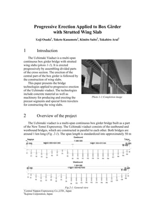
- 1. Progressive Erection Applied to Box Girder with Strutted Wing Slab Koji Osada1 , Taketo Kanamoto1 , Kimito Saito2 , Takahiro Arai2 1 Introduction The Uchimaki Viaduct is a multi-span continuous box girder bridge with strutted wing slabs (photo 1-1). It is erected progressively by assembling divided parts of the cross section. The erection of the central part of the box girder is followed by the construction of wing slabs. This paper presents the bridge technologies applied to progressive erection of the Uchimaki viaduct. The technologies include concrete material as well as machinery for producing and erecting the precast segments and special form travelers for constructing the wing slabs. 2 Overview of the project The Uchimaki viaduct is a multi-span continuous box girder bridge built as a part of the New Tomei Expressway. The Uchimaki viaduct consists of the eastbound and westbound bridges, which are constructed in parallel to each other. Both bridges are around 1 km long (Fig. 2-1). The span length is standardized into approximately 50 m 1 Central Nippon Expressway Co.,LTD., Japan 2 Kajima Corporation, Japan Photo 1-1:Completion image Fig 2-1: General view
- 2. in 36 of the 42 spans in total. Span-by-span erection with precast segments is adopted because of the sufficient project length and standardized spans. The traffic width of the Uchimaki viaduct is 16.5 m, which accommodates three traffic lanes, though many expressways other than the New Tomei and New Meishin expressways have only two traffic lanes. Even with three lanes, the weight of the superstructure and the size of the substructure must be reduced. As a result, diagonal struts supporting the wing slabs are applied to the Uchimaki viaduct. The diagonal struts reduce the deck slab thickness and the bottom slab width (Fig 2-2). Applying span-by-span erection to the box girder with strutted wing slabs, two erection methodologies were compared under the conditions of this project. As the first option, precast segments including the entire cross section (hereafter referred as to ‘whole segment’) are erected. As the other, the cross section is divided into several parts, which are erected progressively. The precast segments exclude large part of the wing slabs and diagonal struts (hereafter referred as to ‘core segment’). As a result, progressive erection with divided parts of cross section was selected. The decision was made because the progressive erection method was found to be beneficial in relation to pier segment erection, fabrication of precast segments and span-by-span erection. In terms of prefabricating segments in particular, it would be impractical to produce whole segments because the casting yard has limited space. The progressive erection applied to the Uchimaki viaduct consists of three major phases (Fig. 2-3). In the first phase, cast-in-situ pier and abutment segments are erected. In the second phase, precast segments are fabricated and erected. In the third phase, precast struts are installed and wing slabs are constructed. In the following section, the erection of whole segments and the progressive erection in each construction phase are compared. In addition, some features in each construction phase are introduced. Fig. 2-2: Cross section Phase 1 Phase 2 Phase 3 Fig 2-3: Construction phases
- 3. 3 Pier and abutment segments 3.1 Comparison of erection methods In a number of precast segmental bridges, pier and abutment segments are fabricated as precast members. However, the pier and abutment segments of the Uchimaki viaduct must be cast-in-situ, because the casting yard that fabricates precast segments is located on a field developed for the New Tomei Expressway adjacent to the bridge (Fig. 3-1). The casting yard is not large enough to set up special casting beds for pier and abutment segments. In addition, the structure of the launching truss for span-by-span erection can be simplified, because an erection truss is not required for erecting pier and abutment segments. In the Uchimaki viaduct, 21 of the 40 pier columns are around 40 m high. All pier columns are designed to have an identical width to the bottom slab width of the box girder (Photo 3-1). This design is selected because a box girder with strutted wing slabs is employed mainly to reduce the size of the substructure. If cast-in-situ whole pier segments were constructed at the top of the pier columns, large falsework carrying wide wing slabs would have been required. Therefore, erection of whole segments would not have been economically viable in relation to cast-in-situ pier segments. On the other hand, casting core segments enable construction using relatively simple supports on the pier columns. From these discussions, progressive erection was determined to be more beneficial in relation to pier segments. A1 A1 Westbound Eastbound 60,800 167,000 Storage Area Re-bar Assembling Area Casting Bed Fig. 3-1: Casting yard Photo 3-1: Completed pier segment
- 4. 3.2 Construction of cast-in-situ core segment In this project, four abutment segments and 40 pier segments on the eastbound and westbound bridges are to be constructed. To construct all pier and abutment segments, four sets of falsework were used in rotation. It took approximately 20 months to erect all cast-in-situ core segments. In the concrete of pier and abutment segments, ordinary Portland cement and low-heat Portland cement were used in spring, autumn and winter, and in summer, respectively to control hydration heat. Water was circulated in the ducts for longitudinal tendons to cool the inside of the segments (Photo 3-1). 4 Prefabrication of typical segment 4.1 Comparison of erection methods As described earlier, precast segments are produced in the relatively small casting yard on the field developed for the New Tomei Expressway. By using precast core segments, 150 segments can be temporarily stored in the yard (Fig. 3-1, Photo 4-1). If precast whole segments had been used, only 80 segments could have been stored, which would have reduced the flexibility of segment prefabrication and erection scheduling, and strict control of schedules would have been impractical. Furthermore, precast whole segments are likely to suffer bowing deformation, because the ratio of segment length (3.0 m) to width (17.680 m) was approximately 1:6, and because the wing slab has a large width of 5.640 m on each side. In relation to the prefabrication of typical segments, progressive erection was found to be more beneficial. 4.2 Fabrication of precast core segment The number of typical core segments to be prefabricated is 636. The typical segment has a length of 3.0 m and weighs 492 kN. The short-line match cast system is employed in this project. Two casting beds are equipped for typical core segments. The box girder has projections at the bottom ends of webs for connection with struts. Then, the side forms are designed to move horizontally to enable the setting of a re-bar cage with the projections (Photo 4-2). Reinforcing bars are Photo 4-1: Completed precast core Photo 4-2: Re-bar cage
- 5. projected from the side edge of the slab to connect with the wing slabs. The formwork at the point was made of wood to facilitate assembly and dismantling. Steam curing was utilized to facilitate concrete hardening in winter. The producing rate for typical segments without deviation block was one per day, and for those with deviation block was one every two days. It took approximately 21 months to prefabricate all typical segments. 5 Span-by-span erection 5.1 Comparison of erection methods Span-by-span erection of the whole segments increases the weight of segments erected in a typical span by approximately 3000 kN, or by 36% over the weight in the case of erecting core segments. The whole segment is 17.680 m wide while the core segment is 9.200 m wide. As mentioned above, the width of the Uchimaki viaduct is relatively large among the highway bridges in Japan. The width of the core segment is close to the width of highways with two traffic lanes generally found in Japan. By using core segments, a launching truss that is applicable to ordinary two-lane highways can be used, whereas erecting the whole segments would have required a special launching truss to accommodate the weight and width of the segment. For span-by-span erection, erecting core segments is considered more beneficial. 5.2 Erection of precast core segment The Uchimaki viaduct is erected over undulating land at the western half (the Nagoya side) and the eastern end. The viaduct also crosses four highways and one river. It is therefore difficult in most of the spans to transport precast segments to the place directly below the span to be erected and to lift them from the launching truss above. The casting yard is located adjacent to the end of the viaduct on the Nagoya side, so vehicles can easily access from the yard to the bridge surface. It was decided to start the erection from the Nagoya end toward Tokyo, and precast segments were transported on the previously erected bridge surface. Photo 5-1: Overhead launching truss Photo 5-2: Polypropylene fiber
- 6. An overhead launching truss was used for span-by-span erection (Photo 5-1). The launching truss weighs approximately 7800 kN. Sixteen segments are assembled in a typical span. Expansive concrete was used for closure joints to avoid cracking due to shrinkage. Polypropylene fibers were mixed into concrete to prevent concrete at closure joints from spalling (Photo 5-2). The erecting rate of typical spans was one span in nine days. 6 Wing slab erection Whole-segment erection is considered to be more advantageous than progressive erection in relation to wing slab because progressive erection of divided parts of the girder cross section requires special form travelers for constructing wing slabs and a longer construction period. In the case where progressive erection is adopted, minimizing the cost of special form travelers and shortening the construction period are very important. After the completion of span-by-span erection of precast core segments, struts are installed and wing slabs are constructed simultaneously at three points using three special form travelers. Multi-functional guide struts are used to reduce the weight of the form traveler (Fig. 6-2). Highly elastic epoxy resin is used at the bottom end connection of the strut. Expansive concrete is used for the wing slabs to prevent cracking due to concrete shrinkage. The procedure for constructing wing slabs using form travelers is shown in Fig. 6-1. Constructing a 15-m-long block takes six days. 6.1 Form travelers It was necessary to minimize the weight of the form traveler to control tensile stress acting on the wing slab as the form traveler advanced. It was also necessary to maximize the length of construction block to shorten the construction period. In this project, form travelers are designed to weigh 1180 kN Guide strut Guide strut Fig. 6-2: Cross section of form traveler (6) Assemble re-bars and post tensioning (7) Place and cure concrete (8) Post tensioning (9) Dismantle formwork (10) Dismantle guide struts and falsework (1) Launch form traveler (2) Assemble guide struts and falsework (3) Assemble formwork in typical sections (4) Install struts (5) Assemble formwork in strut sections Fig. 6-1: Erection procedure for wing slabs
- 7. and enable the construction of 15-m-long blocks (Photo 6-1). The form traveler used in this project is composed of six main frames placed transverse to the bridge axis (Fig. 6-3). The frames are longitudinally connected to one another relatively loosely; loose connection enables the frames to adjust to the horizontal alignment of the bridge and changes in longitudinal or transverse slope. The main structural features of the form traveler are multi-functional diagonal members called ‘guide struts’ (Fig. 6-2). The tip of the guide struts is placed at the bottom end of the web, and the other tip is connected to the vertical member of the main frame on both sides. Using guide struts prevents the number and stiffness of members from increasing, and helps reducing the weight of the form traveler. The functions of the guide strut are described in detail below. The guide struts are integrated with the falsework under the formwork (Fig. 6-2, Photo 6-2). After launching the form traveler, lifting the guide struts and setting the tip of the guide struts at the bottom end of the web complete the assembly of the falsework under the formwork (erection procedure (2)). Similarly, removing the tip of the guide strut from the bottom end of the web and lowering the guide strut complete the dismantling of falsework under the formwork (erection procedure (10)). Supporting struts by guide struts after installing the struts until dismantling the formwork considerably reduces the displacement of struts (Photo 6-2). This is because guide struts increase the overall stiffness of the main frame by directly transmitting compression force to the box girder. The displacement at the top end of the strut during concrete placement is kept to 5 mm. Guide struts keep the displacements at side edges of the wing slabs due to concrete placement to approximately 5 mm (Photo 6-2). This is because the guide struts support the main frames from the box girder. Advancing direction Main frame Fig. 6-3: Side view of form traveler Photo 6-1: Form traveler Photo 6-2:Bottom tip of guide struts
- 8. 6.2 Precast struts Precast struts are employed on the viaduct. The strut of a 300-mm-diamter circular cross section is 5260 mm long and weighs 9.1 kN. Struts are produced at a plant for making concrete products approximately 50 km away from the erection site because the casting yard does not have sufficient space to produce struts as well as pier and abutment segments. The concrete is encased into a fiber reinforced plastic tube to prevent concrete from spalling. The tube is also used as the formwork during concrete placement. The tubes are held vertically when placing concrete. The plant was therefore equipped with a platform to hold the tubes and gantry cranes for lifting concrete buckets to the top of the tubes (Photo 6-3). After assembling the formwork in sections without struts, the bottom end of the strut is connected to the bottom end of the web (erection procedure (4)). Highly elastic epoxy resin is applied as an interface, because a thin layer of epoxy resin ensures that the entire bottom surface of the strut makes contact with the contacting plane at the bottom end of the web. The layer also adjusts the angle of the strut. 7 Conclusions This paper described progressive erection on the Uchimaki Viaduct. Progressive erection was selected after comparing it with the whole segment erection method. Progressive erection enables the downsizing of construction equipment and rational construction in relation to the construction of pier segments and the production and erection of typical segments. For constructing the wing slabs, the weight of the form traveler is reduced to enable the construction of longer blocks of wing slabs and thereby shorten the construction period. Struts are installed in a simple manner. Progressive erection enables the construction of bridges with a large width using smaller construction machinery. For the Uchimaki Viaduct, new form travelers were produced for constructing wing slabs. Progressive construction using existing construction machinery in every erection phase makes the construction more rational. Photo 6-3: Prefabrication of strut
- 9. 8 Recent application of progressive election for the New Tomei project The New Tomei is planed to have its traffic width 16.5m finally. But for reducing the initial construction cost, the traffic width was partially planed to be 10.5m and widen to 16.5m afterward. From the deep consideration of retrofit projects after opening the expressway and under traffic regulations, most of the retrofit projects are extremely hard and have the risk of decline the toll benefit. Therefore, most of the bridge width was determined to be changed to have 16.5m of traffic width initially. At the beginning of construction, the traffic width of Nakanogo viaduct was 10.5m which accommodated two traffic lanes. And the construction has already started. So, progressive election was applied to this bridge. In photo 8-1 to 8-8, the details of the progressive erection are shown. Photo 8-1 Photo 8-2 Launching girder for span-by-span cast-in-situ Completed box girder without plinths at the bottom ends of webs for connection with struts
- 10. Photo 8-3 Photo 8-4 Precast plate for connection with struts Retrofit process for setting precast plate Photo 8-5 Special form traveler for constructing wing slabs
- 11. Photo 8-7 Supporting struts by guide struts after installing the struts until dismantling the formwork Photo 8-6 Special form traveler for constructing wing slabs (close-range view) Supporting struts by guide struts after installing the struts until dismantling the formwork (root of struts in detail) Photo 8-8
- 12. 9 Acknowledgement The authors are grateful to the members of the Technical Committee on the Design and Construction of Prestressed Concrete Bridges with Strutted Wing Slabs chaired by Professor Yamazaki of Nihon University in connection with the Construction of the Uchimaki Viaduct. The authors also thank Mr. Mine of Yokogawa Construction who designed the form traveler for this project. References 1) Kimio SAITO et al.: The Superstructure Design of the Uchimaki Viaduct, The 11th Symposium on Developments in Prestressed Concrete, Japan, Nov., 2001 2) Kimio Saito et al.: Design of Precast Segmental Box Girder Bridge with Strutted Wing Slab, The 1st fib Congress, Japan, Oct., 2002 3) Kimio SAITO et al.: Design of Precast Segment with Deviation Block for Large Capacity External Tendon -Uchimaki Viaduct-, The 12th Symposium on Developments in Prestressed Concrete, Japan, Oct., 2003 4) Kimio SAITO et al.: Span-by-Span Erection Applied to Core Segments of Uchimaki Viaduct, The 13th Symposium on Developments in Prestressed Concrete, Japan, Oct., 2004