SlideShare a Scribd company logo
1 of 60
SINGLE CELL WIRELESS LAN
CONFIGURATION
MULTI-CELL WIRELESS LAN
CONFIGURATION
APPLICATIONS –
CROSS-BUILDING INTERCONNECT
 Connect LANs in nearby buildings
 Point-to-point wireless link
 Connect bridges or routers
 Not a LAN per se
 Usual to include this application under heading of wireless LAN
INFRASTRUCTURE WIRELESS LAN
APPLICATIONS –
AD HOC NETWORKING
 Peer-to-peer network
 Set up temporarily to meet some immediate need
 E.g. group of employees, each with laptop or palmtop, in
business or classroom meeting
 Network for duration of meeting
ADD HOC LAN
WIRELESS LAN REQUIREMENTS
 Same as any LAN
 High capacity, short distances, full connectivity, broadcast capability
 Throughput: efficient use wireless medium
 Number of nodes:Hundreds of nodes across multiple cells
 Connection to backbone LAN: Use control modules to connect to
both types of LANs
 Service area: 100 to 300 m
 Low power consumption:Need long battery life on mobile
stations
 Mustn't require nodes to monitor access points or frequent
handshakes
 Transmission robustness and security:Interference prone and
easily eavesdropped
 Collocated network operation:Two or more wireless LANs in
same area
 License-free operation
 Handoff/roaming: Move from one cell to another
 Dynamic configuration: Addition, deletion, and relocation of end
systems without disruption to users
TECHNOLOGY
 Infrared (IR) LANs: Individual cell of IR LAN limited to
single room
 IR light does not penetrate opaque walls
 Spread spectrum LANs: Mostly operate in ISM
(industrial, scientific, and medical) bands
 No Federal Communications Commission (FCC) licensing is
required in USA
 Narrowband microwave: Microwave frequencies but not
use spread spectrum
 Some require FCC licensing
INFRARED LANS
STRENGTHS AND WEAKNESSES
 Spectrum virtually unlimited
 Infrared spectrum is unregulated worldwide
 Extremely high data rates
 Infrared shares some properties of visible light
 Diffusely reflected by light-colored objects
 Use ceiling reflection to cover entire room
 Does not penetrate walls or other opaque objects
 More easily secured against eavesdropping than microwave
 Separate installation in every room without interference
 Inexpensive and simple
 Uses intensity modulation, so receivers need to detect only
amplitude
 Background radiation
 Sunlight, indoor lighting
 Noise, requiring higher power and limiting range
 Power limited by concerns of eye safety and power
consumption
INFRARED LANS
TRANSMISSION TECHNIQUES
 Directed-beam IR
 Point-to-point links
 Range depends on power and focusing
 Can be kilometers
 Used for building interconnect within line of sight
 Indoor use to set up token ring LAN
 IR transceivers positioned so that data circulate in ring
 Omnidirectional
 Single base station within line of sight of all other stations
 Typically, mounted on ceiling
 Acts as a multiport repeater
 Other transceivers use directional beam aimed at ceiling
unit
 Diffused configuration
 Transmitters are focused and aimed at diffusely reflecting
ceiling
SPREAD SPECTRUM LANS
HUB CONFIGURATION
 Usually use multiple-cell arrangement
 Adjacent cells use different center frequencies
 Hub is typically mounted on ceiling
 Connected to wired LAN
 Connect to stations attached to wired LAN and in other
cells
 May also control access
 IEEE 802.11 point coordination function
 May also act as multiport repeater
 Stations transmit to hub and receive from hub
 Stations may broadcast using an omnidirectional
antenna
 Logical bus configuration
 Hub may do automatic handoff
 Weakening signal, hand off
SPREAD SPECTRUM LANS
PEER-TO-PEER CONFIGURATION
 No hub
 MAC algorithm such as CSMA used to control
access
 Ad hoc LANs
  
SPREAD SPECTRUM LANS
TRANSMISSION ISSUES
 Licensing regulations differ from one country to
another
 USA FCC authorized two unlicensed applications
within the ISM band:
 Spread spectrum - up to 1 watt
 Very low power systems- up to 0.5 watts
 902 - 928 MHz (915-MHz band)
 2.4 - 2.4835 GHz (2.4-GHz band)
 5.725 - 5.825 GHz (5.8-GHz band)
 2.4 GHz also in Europe and Japan
 Higher frequency means higher potential bandwidth
 Interference
 Devices at around 900 MHz, including cordless telephones,
wireless microphones, and amateur radio
 Fewer devices at 2.4 GHz; microwave oven
 Little competition at 5.8 GHz
 Higher frequency band, more expensive equipment
NARROW BAND MICROWAVE LANS
 Just wide enough to accommodate signal
 Until recently, all products used licensed band
 At least one vendor has produced LAN product in
ISM band
LICENSED NARROWBAND RF
 Microwave frequencies usable for voice, data, and video
licensed within specific geographic areas to avoid
interference
 Radium 28 km
 Can contain five licenses
 Each covering two frequencies
 Motorola holds 600 licenses (1200 frequencies) in the 18-GHz
range
 Cover all metropolitan areas with populations of 30,000 or
more in USA
 Use of cell configuration
 Adjacent cells use nonoverlapping frequency bands
 Motorola controls frequency band
 Can assure nearby independent LANs do not interfere
 All transmissions are encrypted
 Licensed narrowband LAN guarantees interference-free
communication
 License holder has legal right tointerference-free data
channel
UNLICENSED NARROWBAND RF
 1995, RadioLAN introduced narrowband wireless
LAN using unlicensed ISM spectrum
 Used for narrowband transmission at low power
 0.5 watts or less
 Operates at 10 Mbps
 5.8-GHz band
 50 m in semiopen office and 100 m in open office
 Peer-to-peer configuration
 Elects one node as dynamic master
 Based on location, interference, and signal strength
 Master can change automatically as conditions
change
 Includes dynamic relay function
 Stations can act as repeater to move data
IEEE 802.11 - BSS
 MAC protocol and physical medium specification for
wireless LANs
 Smallest building block is basic service set (BSS)
 Number of stations
 Same MAC protocol
 Competing for access to same shared wireless medium
 May be isolated or connect to backbone distribution
system (DS) through access point (AP)
 AP functions as bridge
 MAC protocol may be distributed or controlled by
central coordination function in AP
 BSS generally corresponds to cell
 DS can be switch, wired network, or wireless network
BSS CONFIGURATION
 Simplest: each station belongs to single BSS
 Within range only of other stations within BSS
 Can have two BSSs overlap
 Station could participate in more than one BSS
 Association between station and BSS dynamic
 Stations may turn off, come within range, and go out of range
EXTENDED SERVICE SET (ESS)
 Two or more BSS interconnected by DS
 Typically, DS is wired backbone but can be any
network
 Appears as single logical LAN to LLC
ACCESS POINT (AP)
 Logic within station that provides access to DS
 Provides DS services in addition to acting as station
 To integrate IEEE 802.11 architecture with
wired LAN, portal used
 Portal logic implemented in device that is part of
wired LAN and attached to DS
 E.g. Bridge or router
IEEE 802.11 ARCHITECTURE
SERVICES
Service Provider Category
Association Distribution system MSDU delivery
Authentication Station LAN access and
security
Deauthentication Station LAN access and
security
Dissassociation Distribution system MSDU delivery
Distribution Distribution system MSDU delivery
Integration Distribution system MSDU delivery
MSDU delivery Station MSDU delivery
Privacy Station LAN access and
security
Reassocation Distribution system MSDU delivery
CATEGORIZING SERVICES
 Station services implemented in every 802.11
station
 Including AP stations
 Distribution services provided between BSSs
 May be implemented in AP or special-purpose device
 Three services used to control access and
confidentiality
 Six services used to support delivery of MAC
service data units (MSDUs) between stations
 Block of data passed down from MAC user to MAC layer
 Typically LLC PDU
 If MSDU too large for MAC frame, fragment and
transmit in series of frames (see later)
DISTRIBUTION OF MESSAGES
WITHIN A DS
 Distribution is primary service used by stations
to exchange MAC frames when frame must
traverse DS
 From station in one BSS to station in another BSS
 Transport of message through DS is beyond scope of
802.11
 If stations within same BSS, distribution service
logically goes through single AP of that BSS
 Integration service enables transfer of data
between station on 802.11 LAN and one on an
integrated 802.x LAN
 Integrated refers to wired LAN physically connected to
DS
 Stations may be logically connected to 802.11 LAN via
integration service
 Integration service takes care of address translation
ASSOCIATION RELATED SERVICES
 Purpose of MAC layer transfer MSDUs between
MAC entities
 Fulfilled by distribution service (DS)
 DS requires information about stations within
ESS
 Provided by association-related services
 Station must be associated before communicating
 Three transition types of based on mobility
 No transition: Stationary or moves within range of
single BSS
 BSS transition: From one BSS to another within same
ESS
 Requires addressing capability be able to recognize new
location
 ESS transition: From BSS in one ESS to BSS in
STATION LOCATION
 DS needs to know where destination station is
 Identity of AP to which message should be delivered
 Station must maintain association with AP within
current BSS
 Three services relate to this requirement: 
 Association: Establishes initial association between
station and AP
 To make identity and address known
 Station must establish association with AP within
particular BSS
 AP then communicates information to other APs within
ESS
 Reassociation: Transfer established association to
another AP
 Allows station to move from one BSS to another
 Disassociation: From either station or AP that
association is terminated
ACCESS AND PRIVACY SERVICES -
AUTHENTICATION
 On wireless LAN, any station within radio range other
devices can transmit
 Any station within radio range can receive
 Authentication: Used to establish identity of stations to
each other
 Wired LANs assume access to physical connection conveys
authority to connect to LAN
 Not valid assumption for wireless LANs
 Connectivity achieved by having properly tuned antenna
 Authentication service used to establish station identity
 802.11 supports several authentication schemes
 Allows expansion of these schemes
 Does not mandate any particular scheme
 Range from relatively insecure handshaking to public-key
encryption schemes
 802.11 requires mutually acceptable, successful authentication
before association
ACCESS AND PRIVACY SERVICES -
DEAUTHENTICATION AND PRIVACY
 Deauthentication: Invoked whenever an existing
authentication is to be terminated
 Privacy: Used to prevent messages being read by
others
 802.11 provides for optional use of encryption
MEDIUM ACCESS CONTROL
 MAC layer covers three functional areas
 Reliable data delivery
 Access control
 Security
 Beyond our scope
RELIABLE DATA DELIVERY
 802.11 physical and MAC layers subject to
unreliability
 Noise, interference, and other propagation effects
result in loss of frames
 Even with error-correction codes, frames may not
successfully be received
 Can be dealt with at a higher layer, such as TCP
 However, retransmission timers at higher layers
typically order of seconds
 More efficient to deal with errors at the MAC level
 802.11 includes frame exchange protocol
 Station receiving frame returns acknowledgment (ACK)
frame
 Exchange treated as atomic unit
 Not interrupted by any other station
FOUR FRAME EXCHANGE
 Basic data transfer involves exchange of two
frames
 To further enhance reliability, four-frame
exchange may be used
 Source issues a Request to Send (RTS) frame to
destination
 Destination responds with Clear to Send (CTS)
 After receiving CTS, source transmits data
 Destination responds with ACK
 RTS alerts all stations within range of source
that exchange is under way
 CTS alerts all stations within range of
destination
 Stations refrain from transmission to avoid
collision
MEDIA ACCESS CONTROL
 Distributed wireless foundation MAC
(DWFMAC)
 Distributed access control mechanism
 Optional centralized control on top
 Lower sublayer is distributed coordination
function (DCF)
 Contention algorithm to provide access to all traffic
 Asynchronous traffic
 Point coordination function (PCF)
 Centralized MAC algorithm
 Contention free
 Built on top of DCF
IEEE 802.11 PROTOCOL
ARCHITECTURE
DISTRIBUTED COORDINATION
FUNCTION
 DCF sublayer uses CSMA
 If station has frame to transmit, it listens to
medium
 If medium idle, station may transmit
 Otherwise must wait until current transmission
complete
 No collision detection
 Not practical on wireless network
 Dynamic range of signals very large
 Transmitting station cannot distinguish incoming weak
signals from noise and effects of own transmission
 DCF includes delays
 Amounts to priority scheme
 Interframe space
INTERFRAME SPACE
 Single delay known as interframe space (IFS)
 Using IFS, rules for CSMA:
1. Station with frame senses medium
• If idle, wait to see if remains idle for one IFS. If so,
may transmit immediately
1. If busy (either initially or becomes busy during
IFS) station defers transmission
• Continue to monitor until current transmission is over
1. Once current transmission over, delay another
IFS
• If remains idle, back off random time and again sense
• If medium still idle, station may transmit
• During backoff time, if becomes busy, backoff timer is
halted and resumes when medium becomes idle
 To ensure stability, binary exponential backoff
IEEE 802.11
MEDIUM
ACCESS
CONTROL
LOGIC
PRIORITY
 Use three values for IFS
 SIFS (short IFS):
 Shortest IFS
 For all immediate response actions (see later)
 PIFS (point coordination function IFS):
 Midlength IFS
 Used by the centralized controller in PCF scheme when
issuing polls
 DIFS (distributed coordination function IFS):
 Longest IFS
 Used as minimum delay for asynchronous frames
contending for access
SIFS USE - ACK
 Station using SIFS to determine transmission
opportunity has highest priority
 In preference to station waiting PIFS or DIFS time
 SIFS used in following circumstances:
 Acknowledgment (ACK): Station responds with
ACK after waiting SIFS gap
 No collision detection so likelihood of collisions greater
than CSMA/CD
 MAC-level ACK gives efficient collision recovery
 SIFS provide efficient delivery of multiple frame LLC
PDU
 Station with multiframe LLC PDU to transmit sends out
MAC frames one at a time
 Each frame acknowledged after SIFS by recipient
 When source receives ACK, immediately (after SIFS) sends
next frame in sequence
SIFS USE – CTS
 Clear to Send (CTS): Station can ensure data
frame will get through by issuing RTS
 Destination station should immediately respond with
CTS if ready to receive
 All other stations hear RTS and defer
 Poll response: See Point coordination Function
(PCF)
PIFS AND DIFS
 PIFS used by centralized controller
 Issuing polls
 Takes precedence over normal contention traffic
 Frames using SIFS have precedence over PCF poll
 DIFS used for all ordinary asynchronous traffic
IEEE 802.11 MAC TIMING
BASIC ACCESS METHOD
POINT COORDINATION FUNCTION
(PCF)
 Alternative access method implemented on top of DCF
 Polling by centralized polling master (point coordinator)
 Uses PIFS when issuing polls
 PIFS smaller than DIFS
 Can seize medium and lock out all asynchronous traffic while
it issues polls and receives responses
 E.g. wireless network configured so number of stations
with time-sensitive traffic controlled by point coordinator
 Remaining traffic contends for access using CSMA
 Point coordinator polls in round-robin to stations
configured for polling
 When poll issued, polled station may respond using SIFS
 If point coordinator receives response, it issues another poll
using PIFS
 If no response during expected turnaround time,
coordinator issues poll
SUPERFRAME
 Point coordinator would lock out asynchronous traffic by
issuing polls
 Superframe interval defined
 During first part of superframe interval, point coordinator
polls round-robin to all stations configured for polling
 Point coordinator then idles for remainder of superframe
 Allowing contention period for asynchronous access
 At beginning of superframe, point coordinator may seize
control and issue polls for given period
 Time varies because of variable frame size issued by
responding stations
 Rest of superframe available for contention-based access
 At end of superframe interval, point coordinator contends
for access using PIFS
 If idle, point coordinator gains immediate access
 Full superframe period follows
 If busy, point coordinator must wait for idle to gain access
 Results in foreshortened superframe period for next cycle
IEEE 802.11 MAC TIMING
PCF SUPERFRAME CONSTRUCTION
IEEE 802.11 MAC FRAME FORMAT
MAC FRAME FIELDS (1)
 Frame Control:
 Type of frame
 Control, management, or data
 Provides control information
 Includes whether frame is to or from DS, fragmentation
information, and privacy information
 Duration/Connection ID:
 If used as duration field, indicates time (in µs) channel
will be allocated for successful transmission of MAC
frame
 In some control frames, contains association or
connection identifier
 Addresses:
 Number and meaning of address fields depend on
context
 Types include source, destination, transmitting station,
MAC FRAME FIELDS (2)
 Sequence Control:
 4-bit fragment number subfield
 For fragmentation and reassembly
 12-bit sequence number
 Number frames between given transmitter and
receiver
 Frame Body:
 MSDU (or a fragment of)
 LLC PDU or MAC control information
 Frame Check Sequence:
 32-bit cyclic redundancy check
CONTROL FRAMES
 Assist in reliable data delivery 
 Power Save-Poll (PS-Poll)
 Sent by any station to station that includes AP
 Request AP transmit frame buffered for this station while
station in power-saving mode
 Request to Send (RTS)
 First frame in four-way frame exchange
 Clear to Send (CTS)
 Second frame in four-way exchange
 Acknowledgment (ACK)
 Contention-Free (CF)-end
 Announces end of contention-free period part of PCF
 CF-End + CF-Ack:
 Acknowledges CF-end
 Ends contention-free period and releases stations from
associated restrictions
DATA FRAMES – DATA CARRYING
 Eight data frame subtypes, in two groups
 First four carry upper-level data from source
station to destination station
 Data
 Simplest data frame
 May be used in contention or contention-free period
 Data + CF-Ack
 Only sent during contention-free period
 Carries data and acknowledges previously received data
 Data + CF-Poll
 Used by point coordinator to deliver data
 Also to request station send data frame it may have
buffered
 Data + CF-Ack + CF-Poll
DATA FRAMES –
NOT DATA CARRYING
 Remaining four data frames do not carry user
data
 Null Function
 Carries no data, polls, or acknowledgments
 Carries power management bit in frame control field
to AP
 Indicates station is changing to low-power state
 Other three frames (CF-Ack, CF-Poll, CF-Ack +
CF-Poll) same as corresponding frame in
preceding list (Data + CF-Ack, Data + CF-Poll,
Data + CF-Ack + CF-Poll) but without data
MANAGEMENT FRAMES
 Used to manage communications between
stations and Aps
 E.g. management of associations
 Requests, response, reassociation, dissociation, and
authentication
802.11 PHYSICAL LAYER
 Issued in four stages
 First part in 1997
 IEEE 802.11
 Includes MAC layer and three physical layer
specifications
 Two in 2.4-GHz band and one infrared
 All operating at 1 and 2 Mbps
 Two additional parts in 1999
 IEEE 802.11a
 5-GHz band up to 54 Mbps
 IEEE 802.11b
 2.4-GHz band at 5.5 and 11 Mbps
 Most recent in 2002
 IEEE 802.g extends IEEE 802.11b to higher data rates
ORIGINAL 802.11 PHYSICAL LAYER -
DSSS
 Three physical media 
 Direct-sequence spread spectrum
 2.4 GHz ISM band at 1 Mbps and 2 Mbps
 Up to seven channels, each 1 Mbps or 2 Mbps, can be
used
 Depends on bandwidth allocated by various national
regulations
 13 in most European countries
 One in Japan
 Each channel bandwidth 5 MHz
 Encoding scheme DBPSK for 1-Mbps and DQPSK for
2-Mbps
ORIGINAL 802.11 PHYSICAL LAYER -
FHSS
 Frequency-hopping spread spectrum
 2.4 GHz ISM band at 1 Mbps and 2 Mbps
 Uses multiple channels
 Signal hopping from one channel to another based on a
pseudonoise sequence
 1-MHz channels are used
 23 channels in Japan
 70 in USA
 Hopping scheme adjustable
 E.g. Minimum hop rate forUSA is 2.5 hops per second
 Minimum hop distance 6 MHz in North America and most of
Europe and 5 MHz in Japan
 Two-level Gaussian FSK modulation for 1-Mbps
 Bits encoded as deviations from current carrier frequency
 For 2 Mbps, four-level GFSK used
 Four different deviations from center frequency define four 2-
bit combinations
ORIGINAL 802.11 PHYSICAL LAYER –
INFRARED
 Omnidirectional
 Range up to 20 m
 1 Mbps used 16-PPM (pulse position modulation)
 Each group of 4 data bits mapped into one of 16-PPM
symbols
 Each symbol a string of 16 bits
 Each 16-bit string consists of fifteen 0s and one binary 1
 For 2-Mbps, each group of 2 data bits is mapped
into one of four 4-bit sequences
 Each sequence consists of three 0s and one binary 1
 Intensity modulation
 Presence of signal corresponds to 1 
802.11A
 5-GHz band
 Uses orthogonal frequency division multiplexing
(OFDM)
 Not spread spectrum
 Also called multicarrier modulation
 Multiple carrier signals at different frequencies
 Some bits on each channel
 Similar to FDM but all subchannels dedicated to single
source
 Data rates 6, 9, 12, 18, 24, 36, 48, and 54 Mbps
 Up to 52 subcarriers modulated using BPSK,
QPSK, 16-QAM, or 64-QAM
 Depending on rate
 Subcarrier frequency spacing 0.3125 MHz
802.11B
 Extension of 802.11 DS-SS scheme
 5.5 and 11 Mbps
 Chipping rate 11 MHz
 Same as original DS-SS scheme
 Same occupied bandwidth
 Complementary code keying (CCK) modulation to
achieve higher data rate in same bandwidth at same
chipping rate
 CCK modulation complex
 Overview on next slide
 Input data treated in blocks of 8 bits at 1.375 MHz
 8 bits/symbol × 1.375 MHz = 11 Mbps
 Six of these bits mapped into one of 64 code sequences
 Output of mapping, plus two additional bits, forms input to
QPSK modulator
11-MBPS CCK MODULATION
SCHEME
802.11G
 Higher-speed extension to 802.11b
 Combines physical layer encoding techniques
used in 802.11a and 802.11b to provide service at
a variety of data rates
REQUIRED READING
 Stallings chapter 17
 Web sites on 802.11

More Related Content

What's hot

Providing voice and data services in ‘under serviced’ areas - By Rael Lissoos
Providing voice and data services in ‘under serviced’ areas - By Rael LissoosProviding voice and data services in ‘under serviced’ areas - By Rael Lissoos
Providing voice and data services in ‘under serviced’ areas - By Rael LissoosVoiceSA
 
Wlan IEEE 802.11
Wlan IEEE 802.11Wlan IEEE 802.11
Wlan IEEE 802.11Adeel Mirza
 
Ccna Wireless Study Guide
Ccna  Wireless Study GuideCcna  Wireless Study Guide
Ccna Wireless Study GuideCCNAResources
 
WLAN of networking.ppt
WLAN of networking.pptWLAN of networking.ppt
WLAN of networking.pptUmme habiba
 
Wireless LAN Deployment Best Practices
Wireless LAN Deployment Best PracticesWireless LAN Deployment Best Practices
Wireless LAN Deployment Best PracticesMichael Boman
 
Wireless LAN By SAIKIRAN PANJALA
Wireless LAN By SAIKIRAN PANJALAWireless LAN By SAIKIRAN PANJALA
Wireless LAN By SAIKIRAN PANJALASaikiran Panjala
 
WLAN - IEEE 802.11
WLAN - IEEE 802.11WLAN - IEEE 802.11
WLAN - IEEE 802.11Rahul Hada
 
Repeater and hub
Repeater and hubRepeater and hub
Repeater and hubMDSHABBIR12
 
Nwk assignment body copy
Nwk assignment body   copyNwk assignment body   copy
Nwk assignment body copyTonny Michael
 
Wireless Local Area Networks
Wireless Local Area NetworksWireless Local Area Networks
Wireless Local Area NetworksDilum Bandara
 

What's hot (20)

Wireless LAN Technoloy
Wireless LAN TechnoloyWireless LAN Technoloy
Wireless LAN Technoloy
 
Providing voice and data services in ‘under serviced’ areas - By Rael Lissoos
Providing voice and data services in ‘under serviced’ areas - By Rael LissoosProviding voice and data services in ‘under serviced’ areas - By Rael Lissoos
Providing voice and data services in ‘under serviced’ areas - By Rael Lissoos
 
Wlan
WlanWlan
Wlan
 
Iuwne10 S06 L02
Iuwne10 S06 L02Iuwne10 S06 L02
Iuwne10 S06 L02
 
Wlan IEEE 802.11
Wlan IEEE 802.11Wlan IEEE 802.11
Wlan IEEE 802.11
 
Ccna Wireless Study Guide
Ccna  Wireless Study GuideCcna  Wireless Study Guide
Ccna Wireless Study Guide
 
BACKBONE NETWORKS
BACKBONE NETWORKSBACKBONE NETWORKS
BACKBONE NETWORKS
 
Ieee 802.11 wireless lan
Ieee 802.11 wireless lanIeee 802.11 wireless lan
Ieee 802.11 wireless lan
 
WLAN of networking.ppt
WLAN of networking.pptWLAN of networking.ppt
WLAN of networking.ppt
 
Wireless LAN Deployment Best Practices
Wireless LAN Deployment Best PracticesWireless LAN Deployment Best Practices
Wireless LAN Deployment Best Practices
 
Mc wireless lan
Mc wireless lanMc wireless lan
Mc wireless lan
 
Wireless LAN By SAIKIRAN PANJALA
Wireless LAN By SAIKIRAN PANJALAWireless LAN By SAIKIRAN PANJALA
Wireless LAN By SAIKIRAN PANJALA
 
WLAN - IEEE 802.11
WLAN - IEEE 802.11WLAN - IEEE 802.11
WLAN - IEEE 802.11
 
Repeater and hub
Repeater and hubRepeater and hub
Repeater and hub
 
IEEE 802.11 and Bluetooth
IEEE 802.11 and BluetoothIEEE 802.11 and Bluetooth
IEEE 802.11 and Bluetooth
 
Computer Network - Unit 2
Computer Network - Unit 2Computer Network - Unit 2
Computer Network - Unit 2
 
Wlan wireless network
Wlan wireless networkWlan wireless network
Wlan wireless network
 
Nwk assignment body copy
Nwk assignment body   copyNwk assignment body   copy
Nwk assignment body copy
 
Wireless Local Area Networks
Wireless Local Area NetworksWireless Local Area Networks
Wireless Local Area Networks
 
ieee protocols 802.11
ieee protocols 802.11ieee protocols 802.11
ieee protocols 802.11
 

Similar to Wlan 2

Similar to Wlan 2 (20)

12 wireless la-ns
12 wireless la-ns12 wireless la-ns
12 wireless la-ns
 
CS553_ST7_Ch17-WirelessLANs.ppt
CS553_ST7_Ch17-WirelessLANs.pptCS553_ST7_Ch17-WirelessLANs.ppt
CS553_ST7_Ch17-WirelessLANs.ppt
 
WirelessLANs.ppt
WirelessLANs.pptWirelessLANs.ppt
WirelessLANs.ppt
 
WirelessLANs.ppt
WirelessLANs.pptWirelessLANs.ppt
WirelessLANs.ppt
 
Lecture 13
Lecture 13Lecture 13
Lecture 13
 
Introduction to cisco wireless
Introduction to  cisco wirelessIntroduction to  cisco wireless
Introduction to cisco wireless
 
Mobile Computing (Part-2)
Mobile Computing (Part-2)Mobile Computing (Part-2)
Mobile Computing (Part-2)
 
WirelessLANs.pptx
WirelessLANs.pptxWirelessLANs.pptx
WirelessLANs.pptx
 
Unit I Wireless Networks.ppt
Unit I Wireless Networks.pptUnit I Wireless Networks.ppt
Unit I Wireless Networks.ppt
 
Wireless lan
Wireless lanWireless lan
Wireless lan
 
Chapter#13
Chapter#13Chapter#13
Chapter#13
 
Wireless%20networking%20technology(1)
Wireless%20networking%20technology(1)Wireless%20networking%20technology(1)
Wireless%20networking%20technology(1)
 
8. Wireless (1).ppt
8. Wireless (1).ppt8. Wireless (1).ppt
8. Wireless (1).ppt
 
Unit 3
Unit 3Unit 3
Unit 3
 
Wireless Networks.pptx
Wireless Networks.pptxWireless Networks.pptx
Wireless Networks.pptx
 
Wireless networksppt
Wireless networkspptWireless networksppt
Wireless networksppt
 
Wireless networksppt
Wireless networkspptWireless networksppt
Wireless networksppt
 
computer network
computer networkcomputer network
computer network
 
Wireless LAN and bluetooth technology
Wireless LAN and bluetooth technologyWireless LAN and bluetooth technology
Wireless LAN and bluetooth technology
 
Wireless lan
Wireless lanWireless lan
Wireless lan
 

Recently uploaded

CCS355 Neural Network & Deep Learning Unit II Notes with Question bank .pdf
CCS355 Neural Network & Deep Learning Unit II Notes with Question bank .pdfCCS355 Neural Network & Deep Learning Unit II Notes with Question bank .pdf
CCS355 Neural Network & Deep Learning Unit II Notes with Question bank .pdfAsst.prof M.Gokilavani
 
What are the advantages and disadvantages of membrane structures.pptx
What are the advantages and disadvantages of membrane structures.pptxWhat are the advantages and disadvantages of membrane structures.pptx
What are the advantages and disadvantages of membrane structures.pptxwendy cai
 
Risk Assessment For Installation of Drainage Pipes.pdf
Risk Assessment For Installation of Drainage Pipes.pdfRisk Assessment For Installation of Drainage Pipes.pdf
Risk Assessment For Installation of Drainage Pipes.pdfROCENODodongVILLACER
 
complete construction, environmental and economics information of biomass com...
complete construction, environmental and economics information of biomass com...complete construction, environmental and economics information of biomass com...
complete construction, environmental and economics information of biomass com...asadnawaz62
 
IVE Industry Focused Event - Defence Sector 2024
IVE Industry Focused Event - Defence Sector 2024IVE Industry Focused Event - Defence Sector 2024
IVE Industry Focused Event - Defence Sector 2024Mark Billinghurst
 
Call Us ≽ 8377877756 ≼ Call Girls In Shastri Nagar (Delhi)
Call Us ≽ 8377877756 ≼ Call Girls In Shastri Nagar (Delhi)Call Us ≽ 8377877756 ≼ Call Girls In Shastri Nagar (Delhi)
Call Us ≽ 8377877756 ≼ Call Girls In Shastri Nagar (Delhi)dollysharma2066
 
Call Girls Delhi {Jodhpur} 9711199012 high profile service
Call Girls Delhi {Jodhpur} 9711199012 high profile serviceCall Girls Delhi {Jodhpur} 9711199012 high profile service
Call Girls Delhi {Jodhpur} 9711199012 high profile servicerehmti665
 
Introduction-To-Agricultural-Surveillance-Rover.pptx
Introduction-To-Agricultural-Surveillance-Rover.pptxIntroduction-To-Agricultural-Surveillance-Rover.pptx
Introduction-To-Agricultural-Surveillance-Rover.pptxk795866
 
Application of Residue Theorem to evaluate real integrations.pptx
Application of Residue Theorem to evaluate real integrations.pptxApplication of Residue Theorem to evaluate real integrations.pptx
Application of Residue Theorem to evaluate real integrations.pptx959SahilShah
 
Oxy acetylene welding presentation note.
Oxy acetylene welding presentation note.Oxy acetylene welding presentation note.
Oxy acetylene welding presentation note.eptoze12
 
Electronically Controlled suspensions system .pdf
Electronically Controlled suspensions system .pdfElectronically Controlled suspensions system .pdf
Electronically Controlled suspensions system .pdfme23b1001
 
Churning of Butter, Factors affecting .
Churning of Butter, Factors affecting  .Churning of Butter, Factors affecting  .
Churning of Butter, Factors affecting .Satyam Kumar
 
Biology for Computer Engineers Course Handout.pptx
Biology for Computer Engineers Course Handout.pptxBiology for Computer Engineers Course Handout.pptx
Biology for Computer Engineers Course Handout.pptxDeepakSakkari2
 
Effects of rheological properties on mixing
Effects of rheological properties on mixingEffects of rheological properties on mixing
Effects of rheological properties on mixingviprabot1
 
Gfe Mayur Vihar Call Girls Service WhatsApp -> 9999965857 Available 24x7 ^ De...
Gfe Mayur Vihar Call Girls Service WhatsApp -> 9999965857 Available 24x7 ^ De...Gfe Mayur Vihar Call Girls Service WhatsApp -> 9999965857 Available 24x7 ^ De...
Gfe Mayur Vihar Call Girls Service WhatsApp -> 9999965857 Available 24x7 ^ De...srsj9000
 
Artificial-Intelligence-in-Electronics (K).pptx
Artificial-Intelligence-in-Electronics (K).pptxArtificial-Intelligence-in-Electronics (K).pptx
Artificial-Intelligence-in-Electronics (K).pptxbritheesh05
 
INFLUENCE OF NANOSILICA ON THE PROPERTIES OF CONCRETE
INFLUENCE OF NANOSILICA ON THE PROPERTIES OF CONCRETEINFLUENCE OF NANOSILICA ON THE PROPERTIES OF CONCRETE
INFLUENCE OF NANOSILICA ON THE PROPERTIES OF CONCRETEroselinkalist12
 
pipeline in computer architecture design
pipeline in computer architecture  designpipeline in computer architecture  design
pipeline in computer architecture designssuser87fa0c1
 
Decoding Kotlin - Your guide to solving the mysterious in Kotlin.pptx
Decoding Kotlin - Your guide to solving the mysterious in Kotlin.pptxDecoding Kotlin - Your guide to solving the mysterious in Kotlin.pptx
Decoding Kotlin - Your guide to solving the mysterious in Kotlin.pptxJoão Esperancinha
 

Recently uploaded (20)

CCS355 Neural Network & Deep Learning Unit II Notes with Question bank .pdf
CCS355 Neural Network & Deep Learning Unit II Notes with Question bank .pdfCCS355 Neural Network & Deep Learning Unit II Notes with Question bank .pdf
CCS355 Neural Network & Deep Learning Unit II Notes with Question bank .pdf
 
What are the advantages and disadvantages of membrane structures.pptx
What are the advantages and disadvantages of membrane structures.pptxWhat are the advantages and disadvantages of membrane structures.pptx
What are the advantages and disadvantages of membrane structures.pptx
 
Risk Assessment For Installation of Drainage Pipes.pdf
Risk Assessment For Installation of Drainage Pipes.pdfRisk Assessment For Installation of Drainage Pipes.pdf
Risk Assessment For Installation of Drainage Pipes.pdf
 
complete construction, environmental and economics information of biomass com...
complete construction, environmental and economics information of biomass com...complete construction, environmental and economics information of biomass com...
complete construction, environmental and economics information of biomass com...
 
IVE Industry Focused Event - Defence Sector 2024
IVE Industry Focused Event - Defence Sector 2024IVE Industry Focused Event - Defence Sector 2024
IVE Industry Focused Event - Defence Sector 2024
 
Call Us ≽ 8377877756 ≼ Call Girls In Shastri Nagar (Delhi)
Call Us ≽ 8377877756 ≼ Call Girls In Shastri Nagar (Delhi)Call Us ≽ 8377877756 ≼ Call Girls In Shastri Nagar (Delhi)
Call Us ≽ 8377877756 ≼ Call Girls In Shastri Nagar (Delhi)
 
Call Girls Delhi {Jodhpur} 9711199012 high profile service
Call Girls Delhi {Jodhpur} 9711199012 high profile serviceCall Girls Delhi {Jodhpur} 9711199012 high profile service
Call Girls Delhi {Jodhpur} 9711199012 high profile service
 
Introduction-To-Agricultural-Surveillance-Rover.pptx
Introduction-To-Agricultural-Surveillance-Rover.pptxIntroduction-To-Agricultural-Surveillance-Rover.pptx
Introduction-To-Agricultural-Surveillance-Rover.pptx
 
Application of Residue Theorem to evaluate real integrations.pptx
Application of Residue Theorem to evaluate real integrations.pptxApplication of Residue Theorem to evaluate real integrations.pptx
Application of Residue Theorem to evaluate real integrations.pptx
 
Oxy acetylene welding presentation note.
Oxy acetylene welding presentation note.Oxy acetylene welding presentation note.
Oxy acetylene welding presentation note.
 
Electronically Controlled suspensions system .pdf
Electronically Controlled suspensions system .pdfElectronically Controlled suspensions system .pdf
Electronically Controlled suspensions system .pdf
 
Churning of Butter, Factors affecting .
Churning of Butter, Factors affecting  .Churning of Butter, Factors affecting  .
Churning of Butter, Factors affecting .
 
Design and analysis of solar grass cutter.pdf
Design and analysis of solar grass cutter.pdfDesign and analysis of solar grass cutter.pdf
Design and analysis of solar grass cutter.pdf
 
Biology for Computer Engineers Course Handout.pptx
Biology for Computer Engineers Course Handout.pptxBiology for Computer Engineers Course Handout.pptx
Biology for Computer Engineers Course Handout.pptx
 
Effects of rheological properties on mixing
Effects of rheological properties on mixingEffects of rheological properties on mixing
Effects of rheological properties on mixing
 
Gfe Mayur Vihar Call Girls Service WhatsApp -> 9999965857 Available 24x7 ^ De...
Gfe Mayur Vihar Call Girls Service WhatsApp -> 9999965857 Available 24x7 ^ De...Gfe Mayur Vihar Call Girls Service WhatsApp -> 9999965857 Available 24x7 ^ De...
Gfe Mayur Vihar Call Girls Service WhatsApp -> 9999965857 Available 24x7 ^ De...
 
Artificial-Intelligence-in-Electronics (K).pptx
Artificial-Intelligence-in-Electronics (K).pptxArtificial-Intelligence-in-Electronics (K).pptx
Artificial-Intelligence-in-Electronics (K).pptx
 
INFLUENCE OF NANOSILICA ON THE PROPERTIES OF CONCRETE
INFLUENCE OF NANOSILICA ON THE PROPERTIES OF CONCRETEINFLUENCE OF NANOSILICA ON THE PROPERTIES OF CONCRETE
INFLUENCE OF NANOSILICA ON THE PROPERTIES OF CONCRETE
 
pipeline in computer architecture design
pipeline in computer architecture  designpipeline in computer architecture  design
pipeline in computer architecture design
 
Decoding Kotlin - Your guide to solving the mysterious in Kotlin.pptx
Decoding Kotlin - Your guide to solving the mysterious in Kotlin.pptxDecoding Kotlin - Your guide to solving the mysterious in Kotlin.pptx
Decoding Kotlin - Your guide to solving the mysterious in Kotlin.pptx
 

Wlan 2

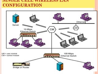
  • 1. SINGLE CELL WIRELESS LAN CONFIGURATION
  • 3. APPLICATIONS – CROSS-BUILDING INTERCONNECT  Connect LANs in nearby buildings  Point-to-point wireless link  Connect bridges or routers  Not a LAN per se  Usual to include this application under heading of wireless LAN
  • 5. APPLICATIONS – AD HOC NETWORKING  Peer-to-peer network  Set up temporarily to meet some immediate need  E.g. group of employees, each with laptop or palmtop, in business or classroom meeting  Network for duration of meeting
  • 7. WIRELESS LAN REQUIREMENTS  Same as any LAN  High capacity, short distances, full connectivity, broadcast capability  Throughput: efficient use wireless medium  Number of nodes:Hundreds of nodes across multiple cells  Connection to backbone LAN: Use control modules to connect to both types of LANs  Service area: 100 to 300 m  Low power consumption:Need long battery life on mobile stations  Mustn't require nodes to monitor access points or frequent handshakes  Transmission robustness and security:Interference prone and easily eavesdropped  Collocated network operation:Two or more wireless LANs in same area  License-free operation  Handoff/roaming: Move from one cell to another  Dynamic configuration: Addition, deletion, and relocation of end systems without disruption to users
  • 8. TECHNOLOGY  Infrared (IR) LANs: Individual cell of IR LAN limited to single room  IR light does not penetrate opaque walls  Spread spectrum LANs: Mostly operate in ISM (industrial, scientific, and medical) bands  No Federal Communications Commission (FCC) licensing is required in USA  Narrowband microwave: Microwave frequencies but not use spread spectrum  Some require FCC licensing
  • 9. INFRARED LANS STRENGTHS AND WEAKNESSES  Spectrum virtually unlimited  Infrared spectrum is unregulated worldwide  Extremely high data rates  Infrared shares some properties of visible light  Diffusely reflected by light-colored objects  Use ceiling reflection to cover entire room  Does not penetrate walls or other opaque objects  More easily secured against eavesdropping than microwave  Separate installation in every room without interference  Inexpensive and simple  Uses intensity modulation, so receivers need to detect only amplitude  Background radiation  Sunlight, indoor lighting  Noise, requiring higher power and limiting range  Power limited by concerns of eye safety and power consumption
  • 10. INFRARED LANS TRANSMISSION TECHNIQUES  Directed-beam IR  Point-to-point links  Range depends on power and focusing  Can be kilometers  Used for building interconnect within line of sight  Indoor use to set up token ring LAN  IR transceivers positioned so that data circulate in ring  Omnidirectional  Single base station within line of sight of all other stations  Typically, mounted on ceiling  Acts as a multiport repeater  Other transceivers use directional beam aimed at ceiling unit  Diffused configuration  Transmitters are focused and aimed at diffusely reflecting ceiling
  • 11. SPREAD SPECTRUM LANS HUB CONFIGURATION  Usually use multiple-cell arrangement  Adjacent cells use different center frequencies  Hub is typically mounted on ceiling  Connected to wired LAN  Connect to stations attached to wired LAN and in other cells  May also control access  IEEE 802.11 point coordination function  May also act as multiport repeater  Stations transmit to hub and receive from hub  Stations may broadcast using an omnidirectional antenna  Logical bus configuration  Hub may do automatic handoff  Weakening signal, hand off
  • 12. SPREAD SPECTRUM LANS PEER-TO-PEER CONFIGURATION  No hub  MAC algorithm such as CSMA used to control access  Ad hoc LANs   
  • 13. SPREAD SPECTRUM LANS TRANSMISSION ISSUES  Licensing regulations differ from one country to another  USA FCC authorized two unlicensed applications within the ISM band:  Spread spectrum - up to 1 watt  Very low power systems- up to 0.5 watts  902 - 928 MHz (915-MHz band)  2.4 - 2.4835 GHz (2.4-GHz band)  5.725 - 5.825 GHz (5.8-GHz band)  2.4 GHz also in Europe and Japan  Higher frequency means higher potential bandwidth  Interference  Devices at around 900 MHz, including cordless telephones, wireless microphones, and amateur radio  Fewer devices at 2.4 GHz; microwave oven  Little competition at 5.8 GHz  Higher frequency band, more expensive equipment
  • 14. NARROW BAND MICROWAVE LANS  Just wide enough to accommodate signal  Until recently, all products used licensed band  At least one vendor has produced LAN product in ISM band
  • 15. LICENSED NARROWBAND RF  Microwave frequencies usable for voice, data, and video licensed within specific geographic areas to avoid interference  Radium 28 km  Can contain five licenses  Each covering two frequencies  Motorola holds 600 licenses (1200 frequencies) in the 18-GHz range  Cover all metropolitan areas with populations of 30,000 or more in USA  Use of cell configuration  Adjacent cells use nonoverlapping frequency bands  Motorola controls frequency band  Can assure nearby independent LANs do not interfere  All transmissions are encrypted  Licensed narrowband LAN guarantees interference-free communication  License holder has legal right tointerference-free data channel
  • 16. UNLICENSED NARROWBAND RF  1995, RadioLAN introduced narrowband wireless LAN using unlicensed ISM spectrum  Used for narrowband transmission at low power  0.5 watts or less  Operates at 10 Mbps  5.8-GHz band  50 m in semiopen office and 100 m in open office  Peer-to-peer configuration  Elects one node as dynamic master  Based on location, interference, and signal strength  Master can change automatically as conditions change  Includes dynamic relay function  Stations can act as repeater to move data
  • 17. IEEE 802.11 - BSS  MAC protocol and physical medium specification for wireless LANs  Smallest building block is basic service set (BSS)  Number of stations  Same MAC protocol  Competing for access to same shared wireless medium  May be isolated or connect to backbone distribution system (DS) through access point (AP)  AP functions as bridge  MAC protocol may be distributed or controlled by central coordination function in AP  BSS generally corresponds to cell  DS can be switch, wired network, or wireless network
  • 18. BSS CONFIGURATION  Simplest: each station belongs to single BSS  Within range only of other stations within BSS  Can have two BSSs overlap  Station could participate in more than one BSS  Association between station and BSS dynamic  Stations may turn off, come within range, and go out of range
  • 19. EXTENDED SERVICE SET (ESS)  Two or more BSS interconnected by DS  Typically, DS is wired backbone but can be any network  Appears as single logical LAN to LLC
  • 20. ACCESS POINT (AP)  Logic within station that provides access to DS  Provides DS services in addition to acting as station  To integrate IEEE 802.11 architecture with wired LAN, portal used  Portal logic implemented in device that is part of wired LAN and attached to DS  E.g. Bridge or router
  • 22. SERVICES Service Provider Category Association Distribution system MSDU delivery Authentication Station LAN access and security Deauthentication Station LAN access and security Dissassociation Distribution system MSDU delivery Distribution Distribution system MSDU delivery Integration Distribution system MSDU delivery MSDU delivery Station MSDU delivery Privacy Station LAN access and security Reassocation Distribution system MSDU delivery
  • 23. CATEGORIZING SERVICES  Station services implemented in every 802.11 station  Including AP stations  Distribution services provided between BSSs  May be implemented in AP or special-purpose device  Three services used to control access and confidentiality  Six services used to support delivery of MAC service data units (MSDUs) between stations  Block of data passed down from MAC user to MAC layer  Typically LLC PDU  If MSDU too large for MAC frame, fragment and transmit in series of frames (see later)
  • 24. DISTRIBUTION OF MESSAGES WITHIN A DS  Distribution is primary service used by stations to exchange MAC frames when frame must traverse DS  From station in one BSS to station in another BSS  Transport of message through DS is beyond scope of 802.11  If stations within same BSS, distribution service logically goes through single AP of that BSS  Integration service enables transfer of data between station on 802.11 LAN and one on an integrated 802.x LAN  Integrated refers to wired LAN physically connected to DS  Stations may be logically connected to 802.11 LAN via integration service  Integration service takes care of address translation
  • 25. ASSOCIATION RELATED SERVICES  Purpose of MAC layer transfer MSDUs between MAC entities  Fulfilled by distribution service (DS)  DS requires information about stations within ESS  Provided by association-related services  Station must be associated before communicating  Three transition types of based on mobility  No transition: Stationary or moves within range of single BSS  BSS transition: From one BSS to another within same ESS  Requires addressing capability be able to recognize new location  ESS transition: From BSS in one ESS to BSS in
  • 26. STATION LOCATION  DS needs to know where destination station is  Identity of AP to which message should be delivered  Station must maintain association with AP within current BSS  Three services relate to this requirement:   Association: Establishes initial association between station and AP  To make identity and address known  Station must establish association with AP within particular BSS  AP then communicates information to other APs within ESS  Reassociation: Transfer established association to another AP  Allows station to move from one BSS to another  Disassociation: From either station or AP that association is terminated
  • 27. ACCESS AND PRIVACY SERVICES - AUTHENTICATION  On wireless LAN, any station within radio range other devices can transmit  Any station within radio range can receive  Authentication: Used to establish identity of stations to each other  Wired LANs assume access to physical connection conveys authority to connect to LAN  Not valid assumption for wireless LANs  Connectivity achieved by having properly tuned antenna  Authentication service used to establish station identity  802.11 supports several authentication schemes  Allows expansion of these schemes  Does not mandate any particular scheme  Range from relatively insecure handshaking to public-key encryption schemes  802.11 requires mutually acceptable, successful authentication before association
  • 28. ACCESS AND PRIVACY SERVICES - DEAUTHENTICATION AND PRIVACY  Deauthentication: Invoked whenever an existing authentication is to be terminated  Privacy: Used to prevent messages being read by others  802.11 provides for optional use of encryption
  • 29. MEDIUM ACCESS CONTROL  MAC layer covers three functional areas  Reliable data delivery  Access control  Security  Beyond our scope
  • 30. RELIABLE DATA DELIVERY  802.11 physical and MAC layers subject to unreliability  Noise, interference, and other propagation effects result in loss of frames  Even with error-correction codes, frames may not successfully be received  Can be dealt with at a higher layer, such as TCP  However, retransmission timers at higher layers typically order of seconds  More efficient to deal with errors at the MAC level  802.11 includes frame exchange protocol  Station receiving frame returns acknowledgment (ACK) frame  Exchange treated as atomic unit  Not interrupted by any other station
  • 31. FOUR FRAME EXCHANGE  Basic data transfer involves exchange of two frames  To further enhance reliability, four-frame exchange may be used  Source issues a Request to Send (RTS) frame to destination  Destination responds with Clear to Send (CTS)  After receiving CTS, source transmits data  Destination responds with ACK  RTS alerts all stations within range of source that exchange is under way  CTS alerts all stations within range of destination  Stations refrain from transmission to avoid collision
  • 32. MEDIA ACCESS CONTROL  Distributed wireless foundation MAC (DWFMAC)  Distributed access control mechanism  Optional centralized control on top  Lower sublayer is distributed coordination function (DCF)  Contention algorithm to provide access to all traffic  Asynchronous traffic  Point coordination function (PCF)  Centralized MAC algorithm  Contention free  Built on top of DCF
  • 34. DISTRIBUTED COORDINATION FUNCTION  DCF sublayer uses CSMA  If station has frame to transmit, it listens to medium  If medium idle, station may transmit  Otherwise must wait until current transmission complete  No collision detection  Not practical on wireless network  Dynamic range of signals very large  Transmitting station cannot distinguish incoming weak signals from noise and effects of own transmission  DCF includes delays  Amounts to priority scheme  Interframe space
  • 35. INTERFRAME SPACE  Single delay known as interframe space (IFS)  Using IFS, rules for CSMA: 1. Station with frame senses medium • If idle, wait to see if remains idle for one IFS. If so, may transmit immediately 1. If busy (either initially or becomes busy during IFS) station defers transmission • Continue to monitor until current transmission is over 1. Once current transmission over, delay another IFS • If remains idle, back off random time and again sense • If medium still idle, station may transmit • During backoff time, if becomes busy, backoff timer is halted and resumes when medium becomes idle  To ensure stability, binary exponential backoff
  • 37. PRIORITY  Use three values for IFS  SIFS (short IFS):  Shortest IFS  For all immediate response actions (see later)  PIFS (point coordination function IFS):  Midlength IFS  Used by the centralized controller in PCF scheme when issuing polls  DIFS (distributed coordination function IFS):  Longest IFS  Used as minimum delay for asynchronous frames contending for access
  • 38. SIFS USE - ACK  Station using SIFS to determine transmission opportunity has highest priority  In preference to station waiting PIFS or DIFS time  SIFS used in following circumstances:  Acknowledgment (ACK): Station responds with ACK after waiting SIFS gap  No collision detection so likelihood of collisions greater than CSMA/CD  MAC-level ACK gives efficient collision recovery  SIFS provide efficient delivery of multiple frame LLC PDU  Station with multiframe LLC PDU to transmit sends out MAC frames one at a time  Each frame acknowledged after SIFS by recipient  When source receives ACK, immediately (after SIFS) sends next frame in sequence
  • 39. SIFS USE – CTS  Clear to Send (CTS): Station can ensure data frame will get through by issuing RTS  Destination station should immediately respond with CTS if ready to receive  All other stations hear RTS and defer  Poll response: See Point coordination Function (PCF)
  • 40. PIFS AND DIFS  PIFS used by centralized controller  Issuing polls  Takes precedence over normal contention traffic  Frames using SIFS have precedence over PCF poll  DIFS used for all ordinary asynchronous traffic
  • 41. IEEE 802.11 MAC TIMING BASIC ACCESS METHOD
  • 42. POINT COORDINATION FUNCTION (PCF)  Alternative access method implemented on top of DCF  Polling by centralized polling master (point coordinator)  Uses PIFS when issuing polls  PIFS smaller than DIFS  Can seize medium and lock out all asynchronous traffic while it issues polls and receives responses  E.g. wireless network configured so number of stations with time-sensitive traffic controlled by point coordinator  Remaining traffic contends for access using CSMA  Point coordinator polls in round-robin to stations configured for polling  When poll issued, polled station may respond using SIFS  If point coordinator receives response, it issues another poll using PIFS  If no response during expected turnaround time, coordinator issues poll
  • 43. SUPERFRAME  Point coordinator would lock out asynchronous traffic by issuing polls  Superframe interval defined  During first part of superframe interval, point coordinator polls round-robin to all stations configured for polling  Point coordinator then idles for remainder of superframe  Allowing contention period for asynchronous access  At beginning of superframe, point coordinator may seize control and issue polls for given period  Time varies because of variable frame size issued by responding stations  Rest of superframe available for contention-based access  At end of superframe interval, point coordinator contends for access using PIFS  If idle, point coordinator gains immediate access  Full superframe period follows  If busy, point coordinator must wait for idle to gain access  Results in foreshortened superframe period for next cycle
  • 44. IEEE 802.11 MAC TIMING PCF SUPERFRAME CONSTRUCTION
  • 45. IEEE 802.11 MAC FRAME FORMAT
  • 46. MAC FRAME FIELDS (1)  Frame Control:  Type of frame  Control, management, or data  Provides control information  Includes whether frame is to or from DS, fragmentation information, and privacy information  Duration/Connection ID:  If used as duration field, indicates time (in µs) channel will be allocated for successful transmission of MAC frame  In some control frames, contains association or connection identifier  Addresses:  Number and meaning of address fields depend on context  Types include source, destination, transmitting station,
  • 47. MAC FRAME FIELDS (2)  Sequence Control:  4-bit fragment number subfield  For fragmentation and reassembly  12-bit sequence number  Number frames between given transmitter and receiver  Frame Body:  MSDU (or a fragment of)  LLC PDU or MAC control information  Frame Check Sequence:  32-bit cyclic redundancy check
  • 48. CONTROL FRAMES  Assist in reliable data delivery   Power Save-Poll (PS-Poll)  Sent by any station to station that includes AP  Request AP transmit frame buffered for this station while station in power-saving mode  Request to Send (RTS)  First frame in four-way frame exchange  Clear to Send (CTS)  Second frame in four-way exchange  Acknowledgment (ACK)  Contention-Free (CF)-end  Announces end of contention-free period part of PCF  CF-End + CF-Ack:  Acknowledges CF-end  Ends contention-free period and releases stations from associated restrictions
  • 49. DATA FRAMES – DATA CARRYING  Eight data frame subtypes, in two groups  First four carry upper-level data from source station to destination station  Data  Simplest data frame  May be used in contention or contention-free period  Data + CF-Ack  Only sent during contention-free period  Carries data and acknowledges previously received data  Data + CF-Poll  Used by point coordinator to deliver data  Also to request station send data frame it may have buffered  Data + CF-Ack + CF-Poll
  • 50. DATA FRAMES – NOT DATA CARRYING  Remaining four data frames do not carry user data  Null Function  Carries no data, polls, or acknowledgments  Carries power management bit in frame control field to AP  Indicates station is changing to low-power state  Other three frames (CF-Ack, CF-Poll, CF-Ack + CF-Poll) same as corresponding frame in preceding list (Data + CF-Ack, Data + CF-Poll, Data + CF-Ack + CF-Poll) but without data
  • 51. MANAGEMENT FRAMES  Used to manage communications between stations and Aps  E.g. management of associations  Requests, response, reassociation, dissociation, and authentication
  • 52. 802.11 PHYSICAL LAYER  Issued in four stages  First part in 1997  IEEE 802.11  Includes MAC layer and three physical layer specifications  Two in 2.4-GHz band and one infrared  All operating at 1 and 2 Mbps  Two additional parts in 1999  IEEE 802.11a  5-GHz band up to 54 Mbps  IEEE 802.11b  2.4-GHz band at 5.5 and 11 Mbps  Most recent in 2002  IEEE 802.g extends IEEE 802.11b to higher data rates
  • 53. ORIGINAL 802.11 PHYSICAL LAYER - DSSS  Three physical media   Direct-sequence spread spectrum  2.4 GHz ISM band at 1 Mbps and 2 Mbps  Up to seven channels, each 1 Mbps or 2 Mbps, can be used  Depends on bandwidth allocated by various national regulations  13 in most European countries  One in Japan  Each channel bandwidth 5 MHz  Encoding scheme DBPSK for 1-Mbps and DQPSK for 2-Mbps
  • 54. ORIGINAL 802.11 PHYSICAL LAYER - FHSS  Frequency-hopping spread spectrum  2.4 GHz ISM band at 1 Mbps and 2 Mbps  Uses multiple channels  Signal hopping from one channel to another based on a pseudonoise sequence  1-MHz channels are used  23 channels in Japan  70 in USA  Hopping scheme adjustable  E.g. Minimum hop rate forUSA is 2.5 hops per second  Minimum hop distance 6 MHz in North America and most of Europe and 5 MHz in Japan  Two-level Gaussian FSK modulation for 1-Mbps  Bits encoded as deviations from current carrier frequency  For 2 Mbps, four-level GFSK used  Four different deviations from center frequency define four 2- bit combinations
  • 55. ORIGINAL 802.11 PHYSICAL LAYER – INFRARED  Omnidirectional  Range up to 20 m  1 Mbps used 16-PPM (pulse position modulation)  Each group of 4 data bits mapped into one of 16-PPM symbols  Each symbol a string of 16 bits  Each 16-bit string consists of fifteen 0s and one binary 1  For 2-Mbps, each group of 2 data bits is mapped into one of four 4-bit sequences  Each sequence consists of three 0s and one binary 1  Intensity modulation  Presence of signal corresponds to 1 
  • 56. 802.11A  5-GHz band  Uses orthogonal frequency division multiplexing (OFDM)  Not spread spectrum  Also called multicarrier modulation  Multiple carrier signals at different frequencies  Some bits on each channel  Similar to FDM but all subchannels dedicated to single source  Data rates 6, 9, 12, 18, 24, 36, 48, and 54 Mbps  Up to 52 subcarriers modulated using BPSK, QPSK, 16-QAM, or 64-QAM  Depending on rate  Subcarrier frequency spacing 0.3125 MHz
  • 57. 802.11B  Extension of 802.11 DS-SS scheme  5.5 and 11 Mbps  Chipping rate 11 MHz  Same as original DS-SS scheme  Same occupied bandwidth  Complementary code keying (CCK) modulation to achieve higher data rate in same bandwidth at same chipping rate  CCK modulation complex  Overview on next slide  Input data treated in blocks of 8 bits at 1.375 MHz  8 bits/symbol × 1.375 MHz = 11 Mbps  Six of these bits mapped into one of 64 code sequences  Output of mapping, plus two additional bits, forms input to QPSK modulator
  • 59. 802.11G  Higher-speed extension to 802.11b  Combines physical layer encoding techniques used in 802.11a and 802.11b to provide service at a variety of data rates
  • 60. REQUIRED READING  Stallings chapter 17  Web sites on 802.11