Drill bits
•Download as PPTX, PDF•
9 likes•5,917 views

This document discusses drill bits used in oil and gas drilling. It describes the main types of drill bits including roller cone bits, natural diamond bits, PDC bits, and TSP bits. It explains how each type of bit cuts rock through different mechanisms like compression, grinding, or shearing. The document also provides details on bit design factors for both roller cone bits and PDC bits, including bearing assembly design, cutter design, nozzle placement, and more. It covers how to select the proper bit based on formation hardness and classify bits using the IADC system. Performance factors like WOB, RPM, mud properties, and hydraulic efficiency that influence bit performance are also summarized.

Recommended
More Related Content
What's hot
What's hot (20)
Similar to Drill bits
Similar to Drill bits (20)
More from Sarwar Alam Ansari
Recently uploaded
Recently uploaded (20)
Drill bits
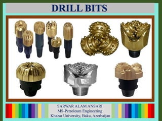
- 1. SARWAR ALAM ANSARI MS-Petroleum Engineering ( Student) SARWAR ALAM ANSARI MS-Petroleum Engineering Khazar University, Baku, Azerbaijan DRILL BITS
- 2. CONTENTS INTRODUCTION TYPES OF DRILLING BIT BIT DESIGN BIT SELECTION ROCK BIT EVALUATION BIT PERFORMANCE
- 3. INTRODUCTION Drilling by compression, crushing, ploughing, grinding and shearing the rock Bits are varied in design The performance of the bit is a function of several parameters WOB (Weight on bit) RPM (Rotation per minute) Mud properties Hydraulic efficiency When bit has drilled a section the damage is recorded using Dull Bit Grading System
- 4. TYPES OF DRILLING BIT Fixed Cutter Roller Cone Drill Bits PDC Diamond Mill tooth Insert Roller BearingTSPNatural Diamond Impreg Friction Bearing
- 5. NATURAL DIAMOND BIT: PLOUGHING/GRINDING PDC BIT: SHEARING F ROLLER CONE BITS: COMPRESSION/CRUSHING F
- 6. TYPES OF DRILLING BIT Drag Bits: First bits used in rotary drilling Not used in industry today Limited to drilling through uniformly, soft, unconsolidated formations where there were no hard abrasive layers. Roller Cone Bits: Drills by compression & crushing action First rollers consisted of 2 cones, but they weren’t successful due to balling of cones with formation Cones are mounted on bearing pins which extend from body Bearings allow cones to rotate around own axis. Steel Tooth type Tungsten Carbide inserts
- 7. TYPES OF DRILLING BIT Natural Diamond Bits Cuts by ploughing & grinding Drilling of hard rock and longer sections Diamonds are bonded on surface of material Sensitive to shock and vibration Very costly (10 times more expensive) Slower ROP than Roller Cones Last longer than Roller cones since no moving parts Formation Diamond Ploughing / Gridning
- 8. TYPES OF DRILLING BIT PDC (Polycrystalline Diamond Compact) Bits: Cuts by Scraping Introduced in 1980s Use small discs of synthetic diamond High ROPs Most widely used in industry today TSP (Thermally stable Polycrystalline) Similar to PDC Tolerant to much higher temperatures Formation PDC Shearing
- 9. BIT DESIGN Roller Cone Bit Design: 1. Bearing assemblies 2. Cone design 3. Cutting elements 4. Fluid circulation
- 10. BIT DESIGN Bearing assembly: Cones are mounted on bearings Three Types of bearing assembly Roller Bearings – help to support radial loading (WOB) Ball bearings – resist longitudinal or thrust loads Friction bearings – in the nose assembly, helps to support radial loading Bearings must be made from toughened steel by heat treatment Most important factor is space availability Ideally Bearing should be large enough to support applied loading Bearing size is balanced with strength of the journal (journal diameter) and strength of cone shell (shell thickness)
- 11. BIT DESIGN Details of Bearing Structure:
- 12. BIT DESIGN Types of bearing assemblies: Sealed Bearing assembly Journal Bearing assembly
- 13. BIT DESIGN Cone Design: Cone design is largely determined by Journal (or pin) angle Cone slippage effect (not even rotation effect) – rock is drilled by grinding + scraping action Magnitude of JA affects the size of the cone If journal angle increases then size of the cone decreases If journal angle decreases then sized of the cone increases Cone slippage is achieved by Design of cones (inner cone gouges, heel scrapesthe rock) Offsetting axes of the cones (offset journals away from the center
- 14. BIT DESIGN The journal angle is the angle at which the journal is mounted, relative to a horizontal plane. Formation Characteristics Insert/Tooth Spacing Insert/Tooth Properties Penetration Drill cut Gen. Cleaning Flow Requirements Soft Wide Long & Sharp High High Intermediate Relatively Wide Shorter & Stubbier Relatively High Relatively High Hard Close Short & Rounded Relatively Low Relatively Low Journal Angle 33 34 - 36 39 Type of formation Soft Medium Hard Cone offset: Soft formation: 0.5 and 0.375 in Hard formation: 0.0325 and 0.0 in
- 15. BIT DESIGN Cutting Elements: Selection is based on hardness of formation to be drilled Main consideration depend on hardness of formation Type of cutter (Steel or Tungsten Carbide inserts) Geometry of cutters (Height, spacing) Soft formations need long, thin, widely spread teeth to prevent bit balling Moderately hard formations have shorter, wider teeth for withstanding heavier loads, wide spread to allow cleaning Hard formations have shortest and stubbier. Spread of cutters is less important due to low ROP and small cuttings sizes Cutter elements are covered with tungsten carbide element to increase its wear resistance
- 16. BIT DESIGN Fluid circulation: Original bit design allowed fluid circulation through the middle of the bit led to build up of cuttings of the face of the bit More efficient way of cleaning face of bit was then introduced circulation through nozzles Jet nozzles are available in many sizes Made of tungsten carbide to prevent fluid erosion Size of nozzle refers to inner diameter of the ring Outside diameter is the same so that it can fit to any size of the bit
- 17. BIT DESIGN PDC Bit Design: Major components of PDC bit design are: Bit body material Bit profile Cutting material Cutter rake Cutter density Cutter exposure Cutter size Fluid circulation
- 18. BIT DESIGN Cutter material PDC : (PCD) Polycrystalline diamond – synthetic material with 90 - 95% pure diamond and manufactured into compacts PCD is formed in 2 stages HPHT process: 1. Manufacture artificial diamond crystals by exposing graphite to high pressures (600,000 psi) in presence of other chemicals 2. Sintering of diamond powder with catalyst/binder in >1400ºC, 750,000 psi Disc cutters and Stud cutters
- 19. BIT DESIGN Cutter material TSP : PDC cutters were chipped while drilling due to internal stresses caused by differential expansion of diamond and binder material (Cobalt) Thermal coefficient of expansion of binder = 1.2 x 10⁻⁵ Thermal coefficient of expansion of diamond = 2.7 x 10⁻⁶ Cobalt expands faster, stresses develop due to different rates of expansion In TSP cutters binder material is removed by leaching with acids to improve stability at higher temperatures Absence of binder material make is impossible to bond TSP to Tungsten carbide substrate Strength of PCD material and substrate is weaker TSP are smaller size and should be set in matrix of the bit
- 20. BIT DESIGN Bit Body Material : Two types of bit body material Steel shell TC (tungsten carbide) shell on steel body Steel body bits Uses stud cutters (can be removed and replaced without damage to bit body, no need for braze) Face erosion is problem (use hard facing) Broken cutters due to limited impact resistance (no support of cutters) Matrix body bits Disc cutters are used in the body Resistant to abrasion and erosion Impact resistance for cutter is provided More expensive
- 21. BIT DESIGN Cutter Rake (back rake and side rake): Back rake – angle between face of cutter and formation (12º to 40º) Angle determines the aggressiveness of the cutters (ROP*, size of cutting that is produced, wear, torque) Smaller the rake angle – more aggressive is the bit (high ROP, bigger cutting, high wear, more torque) as cutters take more depth of cut Opposite is true for big rake angles Side rake – orientation of the cutter from left to right (usually is small Assist hole cleaning my mechanically directing cutting toward annulus
- 22. BIT DESIGN Bit Profile: Three types of PDC bit crown profile Flat or shallow cone (evenly distributes WOB among each of cutters, limited rotational stability, uneven wear) Tapered or double cone (cutters distributed towards OD, even wear, greater rotational and directional stability) Parabolic (smooth loading of the bit profile, even greater rotational and directional capability, even wear)
- 23. BIT DESIGN Bit Length: Shorter bits are more steerable 2 bits on the left are for side-track Third bit is for general directional work
- 24. BIT DESIGN Cutters density: Number of cutters on bit surface per unit area Generally speaking, the harder the formation, the higher the cutter count required High cutter count means that the load is shared across more cutters and therefore each cutter achieves a lower depth of cut (lower ROP) More cutters makes bit more durable If high density is used cutters should be small enough to clean the surface of the bit
- 25. BIT DESIGN Cutters size: PDC cutters are usually available in 8, 11, 13, 16, 19 and 22mm diameters. 13 mm cutters are the most common Increased cutter size means increased torque, increased ROP, decreased durability 8, 11 – hard rock, extended durability 13, 16 – medium hard formations, medium durability 19, 22 – high ROP, less durable, high frictional heat
- 26. BIT DESIGN Cutters exposure: Amount by which the cutters protrude from the bit body. High exposure - to ensure good cleaning of cleaning bit face Lower exposure – good support of the cutters on bit body
- 27. BIT DESIGN Cutter Types: Reed Hycalog: T-Rex and Raptor Smith: GeoMax, SonicMax, GridMax, TecMax Quick Cutter, Arrow Cutter Hughes Christensen: Zenith, ZPlus Security DBS: ERC, ESDRC, CRC, Z3
- 28. BIT DESIGN Fluid circulation: Must be designed to remove the cuttings efficiently and cool the bit surface Design of water courses that run across the bit area Usually 9 jets are available on PDC bits Hydraulic evaluation of bits for cutting structure cleaning and junk slot flow, where fluid and cuttings are efficiently moving away from the hole bottom.
- 29. BIT DESIGN Bit Selection: IADC developed comparison charts for different bits for classifying bits according to their characteristics and application Two systems: Roller Cones and Fixed cutter bits Bits are classified according to IADC codes The position of each bit is defined by three numbers and one character Numbers sequence define “Series, Type and Features” of the bit Additional character defines additional design features
- 31. BIT DESIGN Formations characterization: Soft Unconsolidated clays and sands Low WOB 3000-5000 lbs/in of bit diameter High RPMs (120-250) Medium Formations Shales, Gypsum, Sands, Siltstones Low WOB 3000-6000 lbs/in bit diameter High RPMs (120-250), chalk required less RPM Hard formations Limestone, Anhydrite, Hard sandstone, Dolomite High compressive strength, abrasive material High WOB 6000-10000 lbs/in of bit diameter Slow RPMs (40-100) to help grinding, crushing
- 32. BIT DESIGN PDC bit classification:
- 33. BIT DESIGN IADC Dull bit grading:
- 34. BIT DESIGN Bit performance: Performance determined in How much the bit drilled (ft) How fast it drilled How much it cost per foot of hole drilled Compare one bit with another after well is drilled Bit performance is function of WOB (Weight on bit) RPM (revolutions per minute) Mud properties (Static & Dynamic chip hold down effects) Hydraulic efficiency
- 35. BIT DESIGN Performance of roller cone bits (ROP): Weight on bit (WOB) required to overcome compressibility of formation Limitations on WOB are HHP (Hydraulic horse power) – if there is no enough Hydraulic horsepower at the bit then applying more WOB will not help HHP can be increased either by smaller nozzles sizes or increasing the flow rate
- 36. BIT DESIGN Weight on bit: Type of formations-WOB is limited in soft formations – excessive weight will bury the teeth of bit Hole deviation – bending (or buckling) might happen if too much weight is applied Bearing life – greater the load, the less operational life of bearings Tooth life – in hard formations excessive WOB may cause teeth to break
- 37. BIT DESIGN Revolutions per minute (RPM) ROP varies with RPM for different formations strength Applied RPM depends on Type of bit – lower RPMs are used for insert bits compared to milled tooth bits. Type of formation – hard formations are less easily penetrated and so required low RPMs. High RPM may cause damage to the bit
- 38. BIT DESIGN Mud properties: Hydrostatic pressure provides overbalance for keeping formation fluids in rock Mud cake is formed when fluid invades pores (sand, carbonates) Overbalance and mud cake affect the removal of cuttings Static chip hole down – differential pressure holds the chip on bottom in permeable formations due to inability of fluid penetrate into the crack Dynamics chip hold down – pressure drop when mud flows into cracks in less permeable formations Prevent chip hold down effect reducing the overbalance (lowering MW) and improving solids control Theoretical approach as there are many other factors: time for formation of filter cake, scraping action of the cutters, jet flow from nozzles, bit vibration etc.