SlideShare a Scribd company logo
1 of 12
Download to read offline
e-PG Pathshala
Subject : Computer Science
Paper: Embedded System
Module: I/O devices Interfacing
Module No: CS/ES/16
Quadrant 1 – e-text
In this lecture, the interfacing of 8051 with an output device and an input device are described. The
output device considered is LCD display, and the input device is a matrix-type keyboard. The operation
modes of LCD are first discussed. Interfacing of the LCD to an 8051 microcontroller using Assembly and
C is also discussed. This is followed by the keyboard interface details.
1. LCD (Liquid Crystal Display)interface
LCDs can display numbers, characters, and graphics. To produce a proper display, the information has to
be periodically refreshed. This can be done by the CPU or internally by the LCD device itself.
Incorporating a refreshing controller into the LCD, relieves the CPU of this task and hence many LCDs
have built-in controllers. These controllers also facilitate flexible programming for characters and
graphics. Figure 1.1 shows the pin description of an LCD from Optrex.
Figure 1.1 Pin Descriptions of LCD
Vss and VDD provide +5v and ground, V0 is used for controlling LCD contrast. If RS=0, the instruction
command register is selected, allowing the user to send a command such as clear display, cursor at
home, etc. If RS=1 the data register is selected, allowing the user to send data to be displayed on the
LCD. R/W input allows the user to Read/ Write the information to the LCD. The enable pin is used by the
LCD to latch information presented to its data pins. The 8-bit data pins are used to send information to
LCD. Section 1.1 discusses about command codes for writing the instructions on the LCD register.
Section 1.2 gives an example program for displaying a character on the LCD. Section 1.3 shows the
communication of LCD with a busy flag and section 1.4 gives a detailed explanation of LCD data sheet.
1.1 LCD Command Codes
The LCD’s internal controller can accept several commands and modify the display accordingly.
These commands would be things like:
✓ Clear screen
✓ Return home
✓ Decrement/Increment cursor
After writing to the LCD, it takes some time for it to complete its internal operations. During
this time, it will not accept any new commands or data. Figure 1.2 shows the command codes of
LCD and Figure 1.3 shows the LCD interfacing.
✓ We need to insert a time delay between any two commands or data sent to LCD.
✓ A long delay has to be given between issuing data or commands to the LCD.
Figure 1.2: Command codes of LCD
Figure 1.3 LCD Interfacing
1.2 Program to Display characters on LCD
To send any of the commands to the LCD, make pin RS=0. For data, make RS=1. Then send a high-to-low
pulse to the E pin to enable the internal latch of the LCD. This is shown in the code below.
;calls a time delay before sending next data/command
;P1.0-P1.7 are connected to LCD data pins D0-D7
;P2.0 is connected to RS pin of LCD
;P2.1 is connected to R/W pin of LCD
;P2.2 is connected to E pin of LCD
ORG 0H
MOV A,#38H ;INIT. LCD 2 LINES, 5X7 MATRIX
ACALL COMNWRT ;call command subroutine
ACALL DELAY ;give LCD some time
MOV A,#0EH ;display on, cursor on
ACALL COMNWRT ;call command subroutine
ACALL DELAY ;give LCD some time
MOV A,#01 ;clear LCD
ACALL COMNWRT ;call command subroutine
ACALL DELAY ;give LCD some time
MOV A,#06H ;shift cursor right
ACALL COMNWRT ;call command subroutine
ACALL DELAY ;give LCD some time
MOV A,#84H ;cursor at line 1, pos. 4
ACALL COMNWRT ;call command subroutine
ACALL DELAY ;give LCD some time
MOV A,#’N’ ;display letter N
ACALL DATAWRT ;call display subroutine
ACALL DELAY ;give LCD some time
MOV A,#’O’ ;display letter O
ACALL DATAWRT ;call display subroutine
AGAIN: SJMP AGAIN ;stay here
COMNWRT: ;send command to LCD
MOV P1,A ;copy reg A to port 1
CLR P2.0 ;RS=0 for command
CLR P2.1 ;R/W=0 for write
SETB P2.2 ;E=1 for high pulse
CLR P2.2 ;E=0 for H-to-L pulse
RET
DATAWRT: ;write data to LCD
MOV P1,A ;copy reg A to port 1
SETB P2.0 ;RS=1 for DATA
CLR P2.1 ;R/W=0 for write
SETB P2.2 ;E=1 for high pulse
CLR P2.2 ;E=0 for H-to-L pulse
RET
DELAY: MOV R3,#50 ;50 or higher for fast CPUs
HERE2: MOV R4,#255 ;R4 = 255
HERE: DJNZ R4,HERE ;stay until R4 becomes 0
DJNZ R3,HERE2
RET
END
1.3 Communicating with LCD using the busy flag
The code to communicate with the LCD is given below.
;Check busy flag before sending data, command to LCD
;p1=data pin
;P2.0 connected to RS pin
;P2.1 connected to R/W pin
;P2.2 connected to E pin
MOV A,#38H ;init. LCD 2 lines ,5x7 matrix
ACALL COMMAND ;issue command
MOV A,#0EH ;LCD on, cursor on
ACALL COMMAND ;issue command
MOV A,#01H ;clear LCD command
ACALL COMMAND ;issue command
MOV A,#06H ;shift cursor right
ACALL COMMAND ;issue command
MOV A,#86H ;cursor: line 1, pos. 6
ACALL COMMAND ;command subroutine
MOV A,#’N’ ;display letter N
ACALL DATA_DISPLAY
MOV A,#’O’ ;display letter O
ACALL DATA_DISPLAY
HERE: SJMP HERE ;STAY HERE
COMMAND:
ACALL READY ;is LCD ready?
MOV P1,A ;issue command code
CLR P2.0 ;RS=0 for command
CLR P2.1 ;R/W=0 to write to LCD
SETB P2.2 ;E=1 for H-to-L pulse
CLR P2.2 ;E=0,latch in
RET
DATA_DISPLAY:
ACALL READY ;is LCD ready?
MOV P1,A ;issue data
SETB P2.0 ;RS=1 for data
CLR P2.1 ;R/W =0 to write to LCD
SETB P2.2 ;E=1 for H-to-L pulse
CLR P2.2 ;E=0,latch in
RET
READY:
SETB P1.7 ;make P1.7 input port
CLR P2.0 ;RS=0 access command reg
SETB P2.1 ;R/W=1 read command reg
;read command reg and check busy flag
BACK: SETB P2.2 ;E=1 for H-to-L pulse
CLR P2.2 ;E=0 H-to-L pulse
JB P1.7,BACK ;stay until busy flag=0
RET
END
1.4 LCD data sheet
Figures 1.4 and 1.5 show the LCD timing for read and write.
Figure 1. 4 LCD Timing for Read
Figure 1.5 LCD Timing for Write
1.5 Sending information to LCD with MOVC instruction
The following program shows how to use the MOVC instruction to send data and commands to
an LCD
2. Keyboard interface
We will now look at interfacing keyboards to the microcontroller. Keys in a keyboard are arranged in a
matrix of rows and columns. The controller access both rows and columns through ports. Using two
ports, we can connect to an 8x8 or a 4x4 matrix keyboard. When a key is pressed, a row and column
make a contact, otherwise there is no contact. We will look at the details using a 4x4 keyboard.
2.1 4x4 Keyboard
A 4x4 matrix is connected to two ports as shown in Figure 2.1. The rows are connected to an output
port and the columns are connected to an input port. Port1 of 8051 is connected to the rows of key
matrix, hence it acts as an output port. Port 2 of 8051 is connected to the columns of the key matrix,
hence it acts as an input port. A scanning process is used to identify the key that is pressed.
Figure 2.1 4x4 Keyboard
2.2 Key scan
To find out the key pressed , the controller grounds a row by sending a ‘0’ on the corresponding line of
the output port. It then reads the data at the columns using the input port. If data from columns is D3-
D0=1111, then no key is pressed. If any bit of the column is ‘0’, it indicates that a key is pressed in that
column. In this example, the column is identified by the following values:
1110 – key pressed in column 0
1101 – key pressed in column 1
1011 – key pressed in column 2
0111 – key pressed in column 3
This proceeds as follows.
2.2.1 Steps to find out key pressed
Beginning with the row 0, the microcontroller grounds it by providing a low to row D0 only. It then
reads the columns(port2). If the data read is all 1s, then no key in that row is activated and the
process is moved to the next row. It then grounds the next row, reads the columns, and checks for
any zero. This process continues until a row with a zero is identified. After identification of the
row in which the key has been pressed, the column to which the pressed key belongs is identified
as discussed above - by looking for a zero in the input values read.
Example:
(a) D3 – D0 = 1101 for the row, D3 – D0 = 1011 for the column, indicate row 1 and column 3 are
selected. This indicates that key 6 is pressed.
(b) D3 – D0 = 1011 for the row, D3 – D0 = 0111 for the column, indicate row 2 and column 3 are
selected. Then key ‘B’ is pressed.
2.3 Program:
The program used for detection and identification of the key activated goes through the following
stages:
1. To make sure that the preceding key has been released, 0s are output to all rows at once, and
the columns are read and checked repeatedly until all the columns are high.
● When all columns are found to be high, the program waits for a short amount of time
before it goes to the next stage of waiting for a key to be pressed.
2. To see if any key is pressed, the columns are scanned over and over in an infinite loop until one
of them has a 0 on it.
● Remember that the output latch is connected to rows, still have their initial zeros (in
stage 1), making them grounded.
● After the keypress detection, it waits for 20-ms for the bounce and then scans the
columns again.
a) It ensures that the first key press detection was not an erroneous one due to spike
noise.
b) After the 20-ms delay, if the key is still pressed, then it goes to the loop (step 3) to
detect the actual key pressed.
3. To detect which row the key pressed belongs to, it grounds one row at a time, reading the
columns each time.
• If it finds that all columns are high, this means that the key press does not belong to
that row. Therefore, it grounds the next row and continues until it finds the row, that
the key pressed belongs to.
• Upon finding the row that the key pressed belongs to, it sets up the starting address for
the lookup table holding the scan codes for that row.
4. To identify the key pressed, it rotates the column bits, one bit at a time, into the carry flag and
checks to see if it is low.
• Upon finding the zero, it pulls out the ASCII code for that key from the look-up table.
• Otherwise, it increments the pointer to point to the next element of the look-up table.
2.4 Keyboard Program
The program used for scanning and identifying the pressed key is shown below. The key press detection
is standard for all keyboards but the process for determining which key is pressed varies. The look-up
table method is shown in the following program. It can be modified to work with any matrix upto 8 x 8.
(Program Ref:The 8051 Microcontroller and Embedded Systems Using Assembly and C -Second
Edition )
3. Summary
LCD display, interfacing of LCD with 8051 and the assembly programming are discussed. The Keyboard,
interfacing of Keyboard to 8051 and assembly programming for interfacing are also discussed.
4. References
1. Muhammad Ali Mazidi, Janice Gillispie Mazidi, Rolin D. McKinlay, “The 8051 Microcontroller and
Embedded Systems Using Assembly and C -Second Edition”, New Delhi (2000).

More Related Content

What's hot

What's hot (20)

What are Flip Flops and Its types.
What are Flip Flops and Its types.What are Flip Flops and Its types.
What are Flip Flops and Its types.
 
Chapter7
Chapter7Chapter7
Chapter7
 
Applications of microcontroller(8051)
Applications of microcontroller(8051) Applications of microcontroller(8051)
Applications of microcontroller(8051)
 
Solution manual 8051 microcontroller by mazidi
Solution manual 8051 microcontroller by mazidiSolution manual 8051 microcontroller by mazidi
Solution manual 8051 microcontroller by mazidi
 
Steppert Motor Interfacing With Specific Angle Entered Through Keypad
Steppert Motor Interfacing With Specific Angle Entered Through KeypadSteppert Motor Interfacing With Specific Angle Entered Through Keypad
Steppert Motor Interfacing With Specific Angle Entered Through Keypad
 
8254 PIT
8254 PIT8254 PIT
8254 PIT
 
Shift register
Shift registerShift register
Shift register
 
Dld
DldDld
Dld
 
جميع اوامر لغة الاسمبلي
جميع اوامر لغة الاسمبلي جميع اوامر لغة الاسمبلي
جميع اوامر لغة الاسمبلي
 
Ece221 Ch7 Part1
Ece221 Ch7 Part1Ece221 Ch7 Part1
Ece221 Ch7 Part1
 
4 bit Binary counter
4 bit Binary counter4 bit Binary counter
4 bit Binary counter
 
Ds flip flop
Ds flip flopDs flip flop
Ds flip flop
 
Flipflop
FlipflopFlipflop
Flipflop
 
Counters
CountersCounters
Counters
 
Chapter 4 plc
Chapter 4 plcChapter 4 plc
Chapter 4 plc
 
Programming
ProgrammingProgramming
Programming
 
Programming
ProgrammingProgramming
Programming
 
Digital Counter Design
 Digital Counter Design Digital Counter Design
Digital Counter Design
 
14827 shift registers
14827 shift registers14827 shift registers
14827 shift registers
 
digital elctronics
digital elctronicsdigital elctronics
digital elctronics
 

Similar to Microcontroladores: El microcontrolador 8051 con LCD 16x2

Keypad interfacing 8051 -NANOCDAC
Keypad interfacing 8051 -NANOCDACKeypad interfacing 8051 -NANOCDAC
Keypad interfacing 8051 -NANOCDACnanocdac
 
Micro c lab6(lcd)
Micro c lab6(lcd)Micro c lab6(lcd)
Micro c lab6(lcd)Mashood
 
Customizable Microprocessor design on Nexys 3 Spartan FPGA Board
Customizable Microprocessor design on Nexys 3 Spartan FPGA BoardCustomizable Microprocessor design on Nexys 3 Spartan FPGA Board
Customizable Microprocessor design on Nexys 3 Spartan FPGA BoardBharat Biyani
 
Lab 9 D-Flip Flops: Shift Register and Sequence Counter
Lab 9 D-Flip Flops: Shift Register and Sequence CounterLab 9 D-Flip Flops: Shift Register and Sequence Counter
Lab 9 D-Flip Flops: Shift Register and Sequence CounterKatrina Little
 
Unit iv microcontrollers final
Unit iv microcontrollers finalUnit iv microcontrollers final
Unit iv microcontrollers finalSARITHA REDDY
 
Laboratory exercise 5
Laboratory exercise 5Laboratory exercise 5
Laboratory exercise 5swapnilswap11
 
For this phase of the course project, you will research a bank to .docx
For this phase of the course project, you will research a bank to .docxFor this phase of the course project, you will research a bank to .docx
For this phase of the course project, you will research a bank to .docxhanneloremccaffery
 
Presentation2 1-150523155048-lva1-app6892
Presentation2 1-150523155048-lva1-app6892Presentation2 1-150523155048-lva1-app6892
Presentation2 1-150523155048-lva1-app6892Nirav rathod
 
Calculator design with lcd using fpga
Calculator design with lcd using fpgaCalculator design with lcd using fpga
Calculator design with lcd using fpgaHossam Hassan
 
Lcd interfaing using 8051 and assambly language programming
Lcd interfaing using 8051 and assambly language programmingLcd interfaing using 8051 and assambly language programming
Lcd interfaing using 8051 and assambly language programmingVikas Dongre
 
Electronz_Chapter_12.pptx
Electronz_Chapter_12.pptxElectronz_Chapter_12.pptx
Electronz_Chapter_12.pptxMokete5
 
Micro c lab4(keypad)
Micro c lab4(keypad)Micro c lab4(keypad)
Micro c lab4(keypad)Mashood
 

Similar to Microcontroladores: El microcontrolador 8051 con LCD 16x2 (20)

Interfacing with LCD
Interfacing with LCDInterfacing with LCD
Interfacing with LCD
 
Keypad interfacing 8051 -NANOCDAC
Keypad interfacing 8051 -NANOCDACKeypad interfacing 8051 -NANOCDAC
Keypad interfacing 8051 -NANOCDAC
 
Switch Control and Time Delay - Keypad
Switch Control and Time Delay - KeypadSwitch Control and Time Delay - Keypad
Switch Control and Time Delay - Keypad
 
Micro c lab6(lcd)
Micro c lab6(lcd)Micro c lab6(lcd)
Micro c lab6(lcd)
 
Customizable Microprocessor design on Nexys 3 Spartan FPGA Board
Customizable Microprocessor design on Nexys 3 Spartan FPGA BoardCustomizable Microprocessor design on Nexys 3 Spartan FPGA Board
Customizable Microprocessor design on Nexys 3 Spartan FPGA Board
 
Lab 9 D-Flip Flops: Shift Register and Sequence Counter
Lab 9 D-Flip Flops: Shift Register and Sequence CounterLab 9 D-Flip Flops: Shift Register and Sequence Counter
Lab 9 D-Flip Flops: Shift Register and Sequence Counter
 
Unit iv microcontrollers final
Unit iv microcontrollers finalUnit iv microcontrollers final
Unit iv microcontrollers final
 
Laboratory exercise 5
Laboratory exercise 5Laboratory exercise 5
Laboratory exercise 5
 
For this phase of the course project, you will research a bank to .docx
For this phase of the course project, you will research a bank to .docxFor this phase of the course project, you will research a bank to .docx
For this phase of the course project, you will research a bank to .docx
 
Presentation2 1-150523155048-lva1-app6892
Presentation2 1-150523155048-lva1-app6892Presentation2 1-150523155048-lva1-app6892
Presentation2 1-150523155048-lva1-app6892
 
Analog to Digital .pptx
Analog to Digital .pptxAnalog to Digital .pptx
Analog to Digital .pptx
 
Calculator design with lcd using fpga
Calculator design with lcd using fpgaCalculator design with lcd using fpga
Calculator design with lcd using fpga
 
Lcd & keypad
Lcd & keypadLcd & keypad
Lcd & keypad
 
Lcd interfacing
Lcd interfacingLcd interfacing
Lcd interfacing
 
11. Lecture.pdf
11. Lecture.pdf11. Lecture.pdf
11. Lecture.pdf
 
8051
80518051
8051
 
Lcd interfaing using 8051 and assambly language programming
Lcd interfaing using 8051 and assambly language programmingLcd interfaing using 8051 and assambly language programming
Lcd interfaing using 8051 and assambly language programming
 
Lcd interfacing1
Lcd interfacing1Lcd interfacing1
Lcd interfacing1
 
Electronz_Chapter_12.pptx
Electronz_Chapter_12.pptxElectronz_Chapter_12.pptx
Electronz_Chapter_12.pptx
 
Micro c lab4(keypad)
Micro c lab4(keypad)Micro c lab4(keypad)
Micro c lab4(keypad)
 

More from SANTIAGO PABLO ALBERTO

Manual de teoría y practica electroneumática avanzada
Manual de teoría y practica electroneumática avanzadaManual de teoría y practica electroneumática avanzada
Manual de teoría y practica electroneumática avanzadaSANTIAGO PABLO ALBERTO
 
Programacion de PLC basado en Rslogix 500 por Roni Domínguez
Programacion de PLC basado en Rslogix 500 por Roni Domínguez Programacion de PLC basado en Rslogix 500 por Roni Domínguez
Programacion de PLC basado en Rslogix 500 por Roni Domínguez SANTIAGO PABLO ALBERTO
 
Programación de microcontroladores PIC en C con Fabio Pereira
Programación de microcontroladores PIC en  C con Fabio PereiraProgramación de microcontroladores PIC en  C con Fabio Pereira
Programación de microcontroladores PIC en C con Fabio PereiraSANTIAGO PABLO ALBERTO
 
Análisis y Diseño de Sistemas de Control Digital por Ricardo Fernandez del Bu...
Análisis y Diseño de Sistemas de Control Digital por Ricardo Fernandez del Bu...Análisis y Diseño de Sistemas de Control Digital por Ricardo Fernandez del Bu...
Análisis y Diseño de Sistemas de Control Digital por Ricardo Fernandez del Bu...SANTIAGO PABLO ALBERTO
 
Programación de autómatas PLC OMRON CJ/CP1
Programación de  autómatas PLC OMRON CJ/CP1Programación de  autómatas PLC OMRON CJ/CP1
Programación de autómatas PLC OMRON CJ/CP1SANTIAGO PABLO ALBERTO
 
Manual del sistema del controlador programable S7-200 SMART
Manual del sistema del controlador programable S7-200 SMARTManual del sistema del controlador programable S7-200 SMART
Manual del sistema del controlador programable S7-200 SMARTSANTIAGO PABLO ALBERTO
 
PLC: Buses industriales y de campo practicas de laboratorio por Jose Miguel R...
PLC: Buses industriales y de campo practicas de laboratorio por Jose Miguel R...PLC: Buses industriales y de campo practicas de laboratorio por Jose Miguel R...
PLC: Buses industriales y de campo practicas de laboratorio por Jose Miguel R...SANTIAGO PABLO ALBERTO
 
PLC y Electroneumática: Electricidad y Automatismo eléctrico por Luis Miguel...
PLC y Electroneumática: Electricidad y Automatismo eléctrico por  Luis Miguel...PLC y Electroneumática: Electricidad y Automatismo eléctrico por  Luis Miguel...
PLC y Electroneumática: Electricidad y Automatismo eléctrico por Luis Miguel...SANTIAGO PABLO ALBERTO
 
Electrónica: Diseño y desarrollo de circuitos impresos con Kicad por Miguel P...
Electrónica: Diseño y desarrollo de circuitos impresos con Kicad por Miguel P...Electrónica: Diseño y desarrollo de circuitos impresos con Kicad por Miguel P...
Electrónica: Diseño y desarrollo de circuitos impresos con Kicad por Miguel P...SANTIAGO PABLO ALBERTO
 
PLC: Diseño, construcción y control de un motor doble Dahlander(cuatro veloci...
PLC: Diseño, construcción y control de un motor doble Dahlander(cuatro veloci...PLC: Diseño, construcción y control de un motor doble Dahlander(cuatro veloci...
PLC: Diseño, construcción y control de un motor doble Dahlander(cuatro veloci...SANTIAGO PABLO ALBERTO
 
Electrónica digital: Introducción a la Lógica Digital - Teoría, Problemas y ...
Electrónica digital:  Introducción a la Lógica Digital - Teoría, Problemas y ...Electrónica digital:  Introducción a la Lógica Digital - Teoría, Problemas y ...
Electrónica digital: Introducción a la Lógica Digital - Teoría, Problemas y ...SANTIAGO PABLO ALBERTO
 

More from SANTIAGO PABLO ALBERTO (20)

secuencia electroneumática parte 1
secuencia electroneumática parte 1secuencia electroneumática parte 1
secuencia electroneumática parte 1
 
secuencia electroneumática parte 2
secuencia electroneumática parte 2secuencia electroneumática parte 2
secuencia electroneumática parte 2
 
Manual de teoría y practica electroneumática avanzada
Manual de teoría y practica electroneumática avanzadaManual de teoría y practica electroneumática avanzada
Manual de teoría y practica electroneumática avanzada
 
Programacion de PLC basado en Rslogix 500 por Roni Domínguez
Programacion de PLC basado en Rslogix 500 por Roni Domínguez Programacion de PLC basado en Rslogix 500 por Roni Domínguez
Programacion de PLC basado en Rslogix 500 por Roni Domínguez
 
Programación de microcontroladores PIC en C con Fabio Pereira
Programación de microcontroladores PIC en  C con Fabio PereiraProgramación de microcontroladores PIC en  C con Fabio Pereira
Programación de microcontroladores PIC en C con Fabio Pereira
 
Análisis y Diseño de Sistemas de Control Digital por Ricardo Fernandez del Bu...
Análisis y Diseño de Sistemas de Control Digital por Ricardo Fernandez del Bu...Análisis y Diseño de Sistemas de Control Digital por Ricardo Fernandez del Bu...
Análisis y Diseño de Sistemas de Control Digital por Ricardo Fernandez del Bu...
 
Arduino: Arduino de cero a experto
Arduino: Arduino de cero a expertoArduino: Arduino de cero a experto
Arduino: Arduino de cero a experto
 
Fisica I
Fisica IFisica I
Fisica I
 
Quimica.pdf
Quimica.pdfQuimica.pdf
Quimica.pdf
 
Manual básico PLC OMRON
Manual básico PLC OMRON Manual básico PLC OMRON
Manual básico PLC OMRON
 
Programación de autómatas PLC OMRON CJ/CP1
Programación de  autómatas PLC OMRON CJ/CP1Programación de  autómatas PLC OMRON CJ/CP1
Programación de autómatas PLC OMRON CJ/CP1
 
Manual del sistema del controlador programable S7-200 SMART
Manual del sistema del controlador programable S7-200 SMARTManual del sistema del controlador programable S7-200 SMART
Manual del sistema del controlador programable S7-200 SMART
 
Catálogo de PLC S7-200 SMART
Catálogo de PLC S7-200 SMART Catálogo de PLC S7-200 SMART
Catálogo de PLC S7-200 SMART
 
PLC: Automatismos industriales
PLC: Automatismos industrialesPLC: Automatismos industriales
PLC: Automatismos industriales
 
PLC: Buses industriales y de campo practicas de laboratorio por Jose Miguel R...
PLC: Buses industriales y de campo practicas de laboratorio por Jose Miguel R...PLC: Buses industriales y de campo practicas de laboratorio por Jose Miguel R...
PLC: Buses industriales y de campo practicas de laboratorio por Jose Miguel R...
 
PLC y Electroneumática: Electricidad y Automatismo eléctrico por Luis Miguel...
PLC y Electroneumática: Electricidad y Automatismo eléctrico por  Luis Miguel...PLC y Electroneumática: Electricidad y Automatismo eléctrico por  Luis Miguel...
PLC y Electroneumática: Electricidad y Automatismo eléctrico por Luis Miguel...
 
Electrónica: Diseño y desarrollo de circuitos impresos con Kicad por Miguel P...
Electrónica: Diseño y desarrollo de circuitos impresos con Kicad por Miguel P...Electrónica: Diseño y desarrollo de circuitos impresos con Kicad por Miguel P...
Electrónica: Diseño y desarrollo de circuitos impresos con Kicad por Miguel P...
 
PLC: Diseño, construcción y control de un motor doble Dahlander(cuatro veloci...
PLC: Diseño, construcción y control de un motor doble Dahlander(cuatro veloci...PLC: Diseño, construcción y control de un motor doble Dahlander(cuatro veloci...
PLC: Diseño, construcción y control de un motor doble Dahlander(cuatro veloci...
 
PLC: Motor Dahlander
PLC: Motor DahlanderPLC: Motor Dahlander
PLC: Motor Dahlander
 
Electrónica digital: Introducción a la Lógica Digital - Teoría, Problemas y ...
Electrónica digital:  Introducción a la Lógica Digital - Teoría, Problemas y ...Electrónica digital:  Introducción a la Lógica Digital - Teoría, Problemas y ...
Electrónica digital: Introducción a la Lógica Digital - Teoría, Problemas y ...
 

Recently uploaded

High Profile Call Girls Nashik Megha 7001305949 Independent Escort Service Na...
High Profile Call Girls Nashik Megha 7001305949 Independent Escort Service Na...High Profile Call Girls Nashik Megha 7001305949 Independent Escort Service Na...
High Profile Call Girls Nashik Megha 7001305949 Independent Escort Service Na...Call Girls in Nagpur High Profile
 
Current Transformer Drawing and GTP for MSETCL
Current Transformer Drawing and GTP for MSETCLCurrent Transformer Drawing and GTP for MSETCL
Current Transformer Drawing and GTP for MSETCLDeelipZope
 
GDSC ASEB Gen AI study jams presentation
GDSC ASEB Gen AI study jams presentationGDSC ASEB Gen AI study jams presentation
GDSC ASEB Gen AI study jams presentationGDSCAESB
 
(ANVI) Koregaon Park Call Girls Just Call 7001035870 [ Cash on Delivery ] Pun...
(ANVI) Koregaon Park Call Girls Just Call 7001035870 [ Cash on Delivery ] Pun...(ANVI) Koregaon Park Call Girls Just Call 7001035870 [ Cash on Delivery ] Pun...
(ANVI) Koregaon Park Call Girls Just Call 7001035870 [ Cash on Delivery ] Pun...ranjana rawat
 
Analog to Digital and Digital to Analog Converter
Analog to Digital and Digital to Analog ConverterAnalog to Digital and Digital to Analog Converter
Analog to Digital and Digital to Analog ConverterAbhinavSharma374939
 
Call Girls Delhi {Jodhpur} 9711199012 high profile service
Call Girls Delhi {Jodhpur} 9711199012 high profile serviceCall Girls Delhi {Jodhpur} 9711199012 high profile service
Call Girls Delhi {Jodhpur} 9711199012 high profile servicerehmti665
 
SPICE PARK APR2024 ( 6,793 SPICE Models )
SPICE PARK APR2024 ( 6,793 SPICE Models )SPICE PARK APR2024 ( 6,793 SPICE Models )
SPICE PARK APR2024 ( 6,793 SPICE Models )Tsuyoshi Horigome
 
High Profile Call Girls Nagpur Meera Call 7001035870 Meet With Nagpur Escorts
High Profile Call Girls Nagpur Meera Call 7001035870 Meet With Nagpur EscortsHigh Profile Call Girls Nagpur Meera Call 7001035870 Meet With Nagpur Escorts
High Profile Call Girls Nagpur Meera Call 7001035870 Meet With Nagpur EscortsCall Girls in Nagpur High Profile
 
(RIA) Call Girls Bhosari ( 7001035870 ) HI-Fi Pune Escorts Service
(RIA) Call Girls Bhosari ( 7001035870 ) HI-Fi Pune Escorts Service(RIA) Call Girls Bhosari ( 7001035870 ) HI-Fi Pune Escorts Service
(RIA) Call Girls Bhosari ( 7001035870 ) HI-Fi Pune Escorts Serviceranjana rawat
 
HARDNESS, FRACTURE TOUGHNESS AND STRENGTH OF CERAMICS
HARDNESS, FRACTURE TOUGHNESS AND STRENGTH OF CERAMICSHARDNESS, FRACTURE TOUGHNESS AND STRENGTH OF CERAMICS
HARDNESS, FRACTURE TOUGHNESS AND STRENGTH OF CERAMICSRajkumarAkumalla
 
MANUFACTURING PROCESS-II UNIT-2 LATHE MACHINE
MANUFACTURING PROCESS-II UNIT-2 LATHE MACHINEMANUFACTURING PROCESS-II UNIT-2 LATHE MACHINE
MANUFACTURING PROCESS-II UNIT-2 LATHE MACHINESIVASHANKAR N
 
Coefficient of Thermal Expansion and their Importance.pptx
Coefficient of Thermal Expansion and their Importance.pptxCoefficient of Thermal Expansion and their Importance.pptx
Coefficient of Thermal Expansion and their Importance.pptxAsutosh Ranjan
 
(PRIYA) Rajgurunagar Call Girls Just Call 7001035870 [ Cash on Delivery ] Pun...
(PRIYA) Rajgurunagar Call Girls Just Call 7001035870 [ Cash on Delivery ] Pun...(PRIYA) Rajgurunagar Call Girls Just Call 7001035870 [ Cash on Delivery ] Pun...
(PRIYA) Rajgurunagar Call Girls Just Call 7001035870 [ Cash on Delivery ] Pun...ranjana rawat
 
(MEERA) Dapodi Call Girls Just Call 7001035870 [ Cash on Delivery ] Pune Escorts
(MEERA) Dapodi Call Girls Just Call 7001035870 [ Cash on Delivery ] Pune Escorts(MEERA) Dapodi Call Girls Just Call 7001035870 [ Cash on Delivery ] Pune Escorts
(MEERA) Dapodi Call Girls Just Call 7001035870 [ Cash on Delivery ] Pune Escortsranjana rawat
 
VIP Call Girls Service Hitech City Hyderabad Call +91-8250192130
VIP Call Girls Service Hitech City Hyderabad Call +91-8250192130VIP Call Girls Service Hitech City Hyderabad Call +91-8250192130
VIP Call Girls Service Hitech City Hyderabad Call +91-8250192130Suhani Kapoor
 
Introduction to Multiple Access Protocol.pptx
Introduction to Multiple Access Protocol.pptxIntroduction to Multiple Access Protocol.pptx
Introduction to Multiple Access Protocol.pptxupamatechverse
 

Recently uploaded (20)

High Profile Call Girls Nashik Megha 7001305949 Independent Escort Service Na...
High Profile Call Girls Nashik Megha 7001305949 Independent Escort Service Na...High Profile Call Girls Nashik Megha 7001305949 Independent Escort Service Na...
High Profile Call Girls Nashik Megha 7001305949 Independent Escort Service Na...
 
Current Transformer Drawing and GTP for MSETCL
Current Transformer Drawing and GTP for MSETCLCurrent Transformer Drawing and GTP for MSETCL
Current Transformer Drawing and GTP for MSETCL
 
GDSC ASEB Gen AI study jams presentation
GDSC ASEB Gen AI study jams presentationGDSC ASEB Gen AI study jams presentation
GDSC ASEB Gen AI study jams presentation
 
(ANVI) Koregaon Park Call Girls Just Call 7001035870 [ Cash on Delivery ] Pun...
(ANVI) Koregaon Park Call Girls Just Call 7001035870 [ Cash on Delivery ] Pun...(ANVI) Koregaon Park Call Girls Just Call 7001035870 [ Cash on Delivery ] Pun...
(ANVI) Koregaon Park Call Girls Just Call 7001035870 [ Cash on Delivery ] Pun...
 
★ CALL US 9953330565 ( HOT Young Call Girls In Badarpur delhi NCR
★ CALL US 9953330565 ( HOT Young Call Girls In Badarpur delhi NCR★ CALL US 9953330565 ( HOT Young Call Girls In Badarpur delhi NCR
★ CALL US 9953330565 ( HOT Young Call Girls In Badarpur delhi NCR
 
Analog to Digital and Digital to Analog Converter
Analog to Digital and Digital to Analog ConverterAnalog to Digital and Digital to Analog Converter
Analog to Digital and Digital to Analog Converter
 
Call Girls Delhi {Jodhpur} 9711199012 high profile service
Call Girls Delhi {Jodhpur} 9711199012 high profile serviceCall Girls Delhi {Jodhpur} 9711199012 high profile service
Call Girls Delhi {Jodhpur} 9711199012 high profile service
 
SPICE PARK APR2024 ( 6,793 SPICE Models )
SPICE PARK APR2024 ( 6,793 SPICE Models )SPICE PARK APR2024 ( 6,793 SPICE Models )
SPICE PARK APR2024 ( 6,793 SPICE Models )
 
High Profile Call Girls Nagpur Meera Call 7001035870 Meet With Nagpur Escorts
High Profile Call Girls Nagpur Meera Call 7001035870 Meet With Nagpur EscortsHigh Profile Call Girls Nagpur Meera Call 7001035870 Meet With Nagpur Escorts
High Profile Call Girls Nagpur Meera Call 7001035870 Meet With Nagpur Escorts
 
(RIA) Call Girls Bhosari ( 7001035870 ) HI-Fi Pune Escorts Service
(RIA) Call Girls Bhosari ( 7001035870 ) HI-Fi Pune Escorts Service(RIA) Call Girls Bhosari ( 7001035870 ) HI-Fi Pune Escorts Service
(RIA) Call Girls Bhosari ( 7001035870 ) HI-Fi Pune Escorts Service
 
HARDNESS, FRACTURE TOUGHNESS AND STRENGTH OF CERAMICS
HARDNESS, FRACTURE TOUGHNESS AND STRENGTH OF CERAMICSHARDNESS, FRACTURE TOUGHNESS AND STRENGTH OF CERAMICS
HARDNESS, FRACTURE TOUGHNESS AND STRENGTH OF CERAMICS
 
MANUFACTURING PROCESS-II UNIT-2 LATHE MACHINE
MANUFACTURING PROCESS-II UNIT-2 LATHE MACHINEMANUFACTURING PROCESS-II UNIT-2 LATHE MACHINE
MANUFACTURING PROCESS-II UNIT-2 LATHE MACHINE
 
9953056974 Call Girls In South Ex, Escorts (Delhi) NCR.pdf
9953056974 Call Girls In South Ex, Escorts (Delhi) NCR.pdf9953056974 Call Girls In South Ex, Escorts (Delhi) NCR.pdf
9953056974 Call Girls In South Ex, Escorts (Delhi) NCR.pdf
 
Coefficient of Thermal Expansion and their Importance.pptx
Coefficient of Thermal Expansion and their Importance.pptxCoefficient of Thermal Expansion and their Importance.pptx
Coefficient of Thermal Expansion and their Importance.pptx
 
DJARUM4D - SLOT GACOR ONLINE | SLOT DEMO ONLINE
DJARUM4D - SLOT GACOR ONLINE | SLOT DEMO ONLINEDJARUM4D - SLOT GACOR ONLINE | SLOT DEMO ONLINE
DJARUM4D - SLOT GACOR ONLINE | SLOT DEMO ONLINE
 
(PRIYA) Rajgurunagar Call Girls Just Call 7001035870 [ Cash on Delivery ] Pun...
(PRIYA) Rajgurunagar Call Girls Just Call 7001035870 [ Cash on Delivery ] Pun...(PRIYA) Rajgurunagar Call Girls Just Call 7001035870 [ Cash on Delivery ] Pun...
(PRIYA) Rajgurunagar Call Girls Just Call 7001035870 [ Cash on Delivery ] Pun...
 
Call Us -/9953056974- Call Girls In Vikaspuri-/- Delhi NCR
Call Us -/9953056974- Call Girls In Vikaspuri-/- Delhi NCRCall Us -/9953056974- Call Girls In Vikaspuri-/- Delhi NCR
Call Us -/9953056974- Call Girls In Vikaspuri-/- Delhi NCR
 
(MEERA) Dapodi Call Girls Just Call 7001035870 [ Cash on Delivery ] Pune Escorts
(MEERA) Dapodi Call Girls Just Call 7001035870 [ Cash on Delivery ] Pune Escorts(MEERA) Dapodi Call Girls Just Call 7001035870 [ Cash on Delivery ] Pune Escorts
(MEERA) Dapodi Call Girls Just Call 7001035870 [ Cash on Delivery ] Pune Escorts
 
VIP Call Girls Service Hitech City Hyderabad Call +91-8250192130
VIP Call Girls Service Hitech City Hyderabad Call +91-8250192130VIP Call Girls Service Hitech City Hyderabad Call +91-8250192130
VIP Call Girls Service Hitech City Hyderabad Call +91-8250192130
 
Introduction to Multiple Access Protocol.pptx
Introduction to Multiple Access Protocol.pptxIntroduction to Multiple Access Protocol.pptx
Introduction to Multiple Access Protocol.pptx
 

Microcontroladores: El microcontrolador 8051 con LCD 16x2

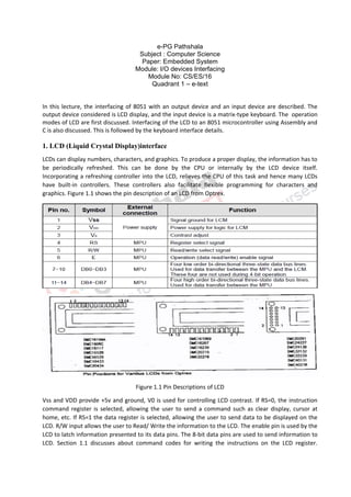
  • 1. e-PG Pathshala Subject : Computer Science Paper: Embedded System Module: I/O devices Interfacing Module No: CS/ES/16 Quadrant 1 – e-text In this lecture, the interfacing of 8051 with an output device and an input device are described. The output device considered is LCD display, and the input device is a matrix-type keyboard. The operation modes of LCD are first discussed. Interfacing of the LCD to an 8051 microcontroller using Assembly and C is also discussed. This is followed by the keyboard interface details. 1. LCD (Liquid Crystal Display)interface LCDs can display numbers, characters, and graphics. To produce a proper display, the information has to be periodically refreshed. This can be done by the CPU or internally by the LCD device itself. Incorporating a refreshing controller into the LCD, relieves the CPU of this task and hence many LCDs have built-in controllers. These controllers also facilitate flexible programming for characters and graphics. Figure 1.1 shows the pin description of an LCD from Optrex. Figure 1.1 Pin Descriptions of LCD Vss and VDD provide +5v and ground, V0 is used for controlling LCD contrast. If RS=0, the instruction command register is selected, allowing the user to send a command such as clear display, cursor at home, etc. If RS=1 the data register is selected, allowing the user to send data to be displayed on the LCD. R/W input allows the user to Read/ Write the information to the LCD. The enable pin is used by the LCD to latch information presented to its data pins. The 8-bit data pins are used to send information to LCD. Section 1.1 discusses about command codes for writing the instructions on the LCD register.
  • 2. Section 1.2 gives an example program for displaying a character on the LCD. Section 1.3 shows the communication of LCD with a busy flag and section 1.4 gives a detailed explanation of LCD data sheet. 1.1 LCD Command Codes The LCD’s internal controller can accept several commands and modify the display accordingly. These commands would be things like: ✓ Clear screen ✓ Return home ✓ Decrement/Increment cursor After writing to the LCD, it takes some time for it to complete its internal operations. During this time, it will not accept any new commands or data. Figure 1.2 shows the command codes of LCD and Figure 1.3 shows the LCD interfacing. ✓ We need to insert a time delay between any two commands or data sent to LCD. ✓ A long delay has to be given between issuing data or commands to the LCD. Figure 1.2: Command codes of LCD
  • 3. Figure 1.3 LCD Interfacing 1.2 Program to Display characters on LCD To send any of the commands to the LCD, make pin RS=0. For data, make RS=1. Then send a high-to-low pulse to the E pin to enable the internal latch of the LCD. This is shown in the code below. ;calls a time delay before sending next data/command ;P1.0-P1.7 are connected to LCD data pins D0-D7 ;P2.0 is connected to RS pin of LCD ;P2.1 is connected to R/W pin of LCD ;P2.2 is connected to E pin of LCD ORG 0H MOV A,#38H ;INIT. LCD 2 LINES, 5X7 MATRIX ACALL COMNWRT ;call command subroutine ACALL DELAY ;give LCD some time MOV A,#0EH ;display on, cursor on ACALL COMNWRT ;call command subroutine ACALL DELAY ;give LCD some time MOV A,#01 ;clear LCD ACALL COMNWRT ;call command subroutine ACALL DELAY ;give LCD some time
  • 4. MOV A,#06H ;shift cursor right ACALL COMNWRT ;call command subroutine ACALL DELAY ;give LCD some time MOV A,#84H ;cursor at line 1, pos. 4 ACALL COMNWRT ;call command subroutine ACALL DELAY ;give LCD some time MOV A,#’N’ ;display letter N ACALL DATAWRT ;call display subroutine ACALL DELAY ;give LCD some time MOV A,#’O’ ;display letter O ACALL DATAWRT ;call display subroutine AGAIN: SJMP AGAIN ;stay here COMNWRT: ;send command to LCD MOV P1,A ;copy reg A to port 1 CLR P2.0 ;RS=0 for command CLR P2.1 ;R/W=0 for write SETB P2.2 ;E=1 for high pulse CLR P2.2 ;E=0 for H-to-L pulse RET DATAWRT: ;write data to LCD MOV P1,A ;copy reg A to port 1 SETB P2.0 ;RS=1 for DATA CLR P2.1 ;R/W=0 for write SETB P2.2 ;E=1 for high pulse CLR P2.2 ;E=0 for H-to-L pulse RET DELAY: MOV R3,#50 ;50 or higher for fast CPUs HERE2: MOV R4,#255 ;R4 = 255 HERE: DJNZ R4,HERE ;stay until R4 becomes 0 DJNZ R3,HERE2 RET
  • 5. END 1.3 Communicating with LCD using the busy flag The code to communicate with the LCD is given below. ;Check busy flag before sending data, command to LCD ;p1=data pin ;P2.0 connected to RS pin ;P2.1 connected to R/W pin ;P2.2 connected to E pin MOV A,#38H ;init. LCD 2 lines ,5x7 matrix ACALL COMMAND ;issue command MOV A,#0EH ;LCD on, cursor on ACALL COMMAND ;issue command MOV A,#01H ;clear LCD command ACALL COMMAND ;issue command MOV A,#06H ;shift cursor right ACALL COMMAND ;issue command MOV A,#86H ;cursor: line 1, pos. 6 ACALL COMMAND ;command subroutine MOV A,#’N’ ;display letter N ACALL DATA_DISPLAY MOV A,#’O’ ;display letter O ACALL DATA_DISPLAY HERE: SJMP HERE ;STAY HERE COMMAND: ACALL READY ;is LCD ready? MOV P1,A ;issue command code CLR P2.0 ;RS=0 for command CLR P2.1 ;R/W=0 to write to LCD SETB P2.2 ;E=1 for H-to-L pulse CLR P2.2 ;E=0,latch in RET
  • 6. DATA_DISPLAY: ACALL READY ;is LCD ready? MOV P1,A ;issue data SETB P2.0 ;RS=1 for data CLR P2.1 ;R/W =0 to write to LCD SETB P2.2 ;E=1 for H-to-L pulse CLR P2.2 ;E=0,latch in RET READY: SETB P1.7 ;make P1.7 input port CLR P2.0 ;RS=0 access command reg SETB P2.1 ;R/W=1 read command reg ;read command reg and check busy flag BACK: SETB P2.2 ;E=1 for H-to-L pulse CLR P2.2 ;E=0 H-to-L pulse JB P1.7,BACK ;stay until busy flag=0 RET END 1.4 LCD data sheet Figures 1.4 and 1.5 show the LCD timing for read and write.
  • 7. Figure 1. 4 LCD Timing for Read Figure 1.5 LCD Timing for Write
  • 8. 1.5 Sending information to LCD with MOVC instruction The following program shows how to use the MOVC instruction to send data and commands to an LCD 2. Keyboard interface
  • 9. We will now look at interfacing keyboards to the microcontroller. Keys in a keyboard are arranged in a matrix of rows and columns. The controller access both rows and columns through ports. Using two ports, we can connect to an 8x8 or a 4x4 matrix keyboard. When a key is pressed, a row and column make a contact, otherwise there is no contact. We will look at the details using a 4x4 keyboard. 2.1 4x4 Keyboard A 4x4 matrix is connected to two ports as shown in Figure 2.1. The rows are connected to an output port and the columns are connected to an input port. Port1 of 8051 is connected to the rows of key matrix, hence it acts as an output port. Port 2 of 8051 is connected to the columns of the key matrix, hence it acts as an input port. A scanning process is used to identify the key that is pressed. Figure 2.1 4x4 Keyboard 2.2 Key scan To find out the key pressed , the controller grounds a row by sending a ‘0’ on the corresponding line of the output port. It then reads the data at the columns using the input port. If data from columns is D3- D0=1111, then no key is pressed. If any bit of the column is ‘0’, it indicates that a key is pressed in that column. In this example, the column is identified by the following values: 1110 – key pressed in column 0 1101 – key pressed in column 1 1011 – key pressed in column 2 0111 – key pressed in column 3 This proceeds as follows. 2.2.1 Steps to find out key pressed Beginning with the row 0, the microcontroller grounds it by providing a low to row D0 only. It then reads the columns(port2). If the data read is all 1s, then no key in that row is activated and the process is moved to the next row. It then grounds the next row, reads the columns, and checks for any zero. This process continues until a row with a zero is identified. After identification of the row in which the key has been pressed, the column to which the pressed key belongs is identified as discussed above - by looking for a zero in the input values read. Example:
  • 10. (a) D3 – D0 = 1101 for the row, D3 – D0 = 1011 for the column, indicate row 1 and column 3 are selected. This indicates that key 6 is pressed. (b) D3 – D0 = 1011 for the row, D3 – D0 = 0111 for the column, indicate row 2 and column 3 are selected. Then key ‘B’ is pressed. 2.3 Program: The program used for detection and identification of the key activated goes through the following stages: 1. To make sure that the preceding key has been released, 0s are output to all rows at once, and the columns are read and checked repeatedly until all the columns are high. ● When all columns are found to be high, the program waits for a short amount of time before it goes to the next stage of waiting for a key to be pressed. 2. To see if any key is pressed, the columns are scanned over and over in an infinite loop until one of them has a 0 on it. ● Remember that the output latch is connected to rows, still have their initial zeros (in stage 1), making them grounded. ● After the keypress detection, it waits for 20-ms for the bounce and then scans the columns again. a) It ensures that the first key press detection was not an erroneous one due to spike noise. b) After the 20-ms delay, if the key is still pressed, then it goes to the loop (step 3) to detect the actual key pressed. 3. To detect which row the key pressed belongs to, it grounds one row at a time, reading the columns each time. • If it finds that all columns are high, this means that the key press does not belong to that row. Therefore, it grounds the next row and continues until it finds the row, that the key pressed belongs to. • Upon finding the row that the key pressed belongs to, it sets up the starting address for the lookup table holding the scan codes for that row. 4. To identify the key pressed, it rotates the column bits, one bit at a time, into the carry flag and checks to see if it is low. • Upon finding the zero, it pulls out the ASCII code for that key from the look-up table. • Otherwise, it increments the pointer to point to the next element of the look-up table. 2.4 Keyboard Program The program used for scanning and identifying the pressed key is shown below. The key press detection is standard for all keyboards but the process for determining which key is pressed varies. The look-up table method is shown in the following program. It can be modified to work with any matrix upto 8 x 8.
  • 11.
  • 12. (Program Ref:The 8051 Microcontroller and Embedded Systems Using Assembly and C -Second Edition ) 3. Summary LCD display, interfacing of LCD with 8051 and the assembly programming are discussed. The Keyboard, interfacing of Keyboard to 8051 and assembly programming for interfacing are also discussed. 4. References 1. Muhammad Ali Mazidi, Janice Gillispie Mazidi, Rolin D. McKinlay, “The 8051 Microcontroller and Embedded Systems Using Assembly and C -Second Edition”, New Delhi (2000).