Call Girls In Bangalore ☎ 7737669865 🥵 Book Your One night Stand
Electronz_Chapter_12.pptx
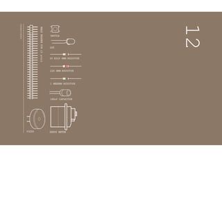
1. INGREDIENTS
10 KILO OHM RESISTOR
220 OHM RESISTOR
1 MEGOHM RESISTOR
SWITCH
LED
12
PIEZO SERVO MOTOR
100uF CAPACITOR
MALE
HEADER
PIN
(
3
p
i
n
s
)
2. MAKE YOUR OWN SECRET LOCKING MECHANISM TO KEEP
UNWANTED GUESTS OUT OF YOUR SPACE!
The piezo you used for playing back sounds in the theremin and keyboard pro-
jects can also be used as an input device. When plugged into 5V, the sensor can
detect vibrations that can be read by the Arduino’s analog inputs. You’ll need to
plug in a high value resistor (like 1-megohm) as the reference to ground for this
to work well.
When the piezo is pressed flat against a solid surface that can vibrate, like a wood-
en table top, your Arduino can sense how intense a knock is. Using this informa-
tion you can check to see ifa number of knocks fall in an acceptable range. In code
you can track the number of knocks and see if they match your settings.
A switch will let you lock the motor in place. Some LEDs will give you status: a red
LED will indicate the box is locked, a green LED will indicate the box is unlocked,
and a yellow LED lets you know if a valid knock has been received.
You’llalso be writing your own function that will letyou know ifa knock is too loud
or too soft. Writing your own function helps save time programming by reusing
code instead of writing it out many times. Functions can take arguments and
return values. In this case, you’ll give a function the volume of the knock. If it is in
the right range, you’ll increment a variable.
It’s possible to build the circuit by itself, but it’s much more fun if you use this as
a tool to lock something. If you have a wooden or a cardboard box you can cut
holes into, use the servo motor to open and close a latch, keeping people from
getting at your stuff.
Discover: input with a piezo, writing your own functions
Time: 1HOUR Builds on projects: 1
,2,3,4,5
Level:
KNOCK
LOCK
125
4. There are a lot of connections on the board, be sure to keep
track of how things are wired up.
Connect power and ground to both sides of the breadboard.
Place the pushbutton on the breadboard and connect one
end to 5V. On the other side of the switch, connect to ground
through a 10-kilohm resistor. Connect this junction to digital
pin 2 on the Arduino.
Attach the wires from the piezo to the breadboard. Attach one
wire to power. If your piezo has a red wire or one marked with
a “+”,that is the one to connect to power. If your piezo doesn’t
indicate polarity, then you can hook it up either way. Wire
the other end of the piezo to Analog Pin 0 on your Arduino.
Place a 1-megohm resistor between the ground and the other
wire. Lower resistor values will make the piezo less sensitive to
vibrations.
Wire up the LEDs, connecting the cathodes (short leg) to
ground, and placing a 220-ohm resistor in series with the an-
odes. Through their respective resistors, connect the yellow
LED to Arduino digital pin 3, the green LED to digital pin 4, and
the red LED to digital pin 5.
Insert the male headers into the female socket on the servo
motor (see Fig.3). Connect the red wire to power, and the black
wire to ground. Place a 100uF electrolytic capacitor across
power and ground to smooth out any irregularities in voltage,
making sure you have the capacitor’s polarity correct. Connect
the servo’s data wire to pin 9 on your Arduino.
❶
❷
❸
❹
Yourservo motor comes with
female connectors, soyou’ll
need to addheader pins to
connect it to the breadboard.
Fig.3
127
5. Just as in the earlier Mood Cue Project, you’ll need to import the
Servo library and createan instance to use the motor.
Create constants to name your inputs and outputs.
Create variables to hold the values from your switch and piezo.
Set up some constants to use as thresholds for the knock
maximum and minimum levels.
The locked variable will let you know if the lock is enganged or
not. A boolean is a data type that can only be true (1) or false
(0). You should start with the mechanism unlocked.
The last global variable will hold the number of valid knocks you
have received.
In your setup(),attach the servo to pin 9.
Set the LED pins as outputs and the switch pins as inputs.
Initialize serial communication with the computer so you can
monitor the knock volume, what the current state of the lock is,
and how many more knocks you have to go.
Turn on the green LED, move the servo to the unlocked position,
and print the current status to the serial monitor indicating the
circuit is in the unlocked position.
In the loop(), you’ll first check to see if the box is locked or not.
This will determine what happens in the rest of the program. If it
is locked, read the switch value.
THE CODE
Servo library
Useful constants
Variables to hold switch and
piezo values
Knock tresholds
Variables for lock state and
numberof knocks
Setting the direction of the
digital pinsandinitializing
servo object andserial port
Unlock
Checking the switch
128 Project 12
Knock Lock
6. 1 #incLude <Servo.h>
2 Servo myServo;
3 const int piezo = A0;
4 const int switchPin = 2;
5 const int yeLLowLed = 3;
6 const int greenLed = 4;
7 const int redLed = 5;
8 int knockVaL;
9 int switchVaL;
10 const int quietKnock = 10;
11 const int LoudKnock = 100;
12 booLean Locked = faLse;
13 int numberOfKnocks = 0;
14 void setup(){
15 myServo.attach(9);
16 pinMode(yeLLowLed, OUTPUT);
17 pinMode(redLed, OUTPUT);
18 pinMode(greenLed, OUTPUT);
19 pinMode(switchPin, INPUT);
20 SeriaL.begin(9600);
21 digitaLWrite(greenLed, HIGH);
22 myServo.write(0);
23SeriaL.printLn(“The box is unLocked!”); 24
}
25 void Loop(){
26 if(Locked == faLse){
27 switchVaL = digitaLRead(switchPin);
129
7. If the switch is closed (you’re pressing it), change the locked
variable to true, indicating the lock is engaged. Turn the green
LED off, and the red LED on. If you don’t have the serial monitor
on, this is helpful visual feedback to let you know the status of
the lock. Move the servo into the lock position, and print out a
message to the serial monitor indicating the box is now locked.
Add a delay so the lock has plenty of time to move into place.
If the locked variable is true, and the lock is engaged, read the
value of the vibration of the piezo and store it in knockVal.
The next statement checks to see if you have fewer than three
valid knocks, and there is some vibration on the sensor. If these
are both true, check to see if this current knock is valid or not and
increment the numberOfKnocks variable. This is where you’ll
call your custom function checkForKnocks(). You’ll write the
function once you’re finished with the loop(), but you already
know you’re going to be asking it if this is a valid knock, so pass
the knockVal along as an argument. After checking your function,
print out the number of knock still needed.
Check to see if you have three or more valid knocks. If this is
true, change the locked variable to false, and move the servo to
the unlocked position. Wait for a few milliseconds to let it start
moving, and change the status of the green and red LEDs. Print
out a status message to the serial monitor, indicating the box is
unlocked.
Close up the else statement and the loop() with a pair of
curly brackets.
Now it’s time to write the function checkForKnock(). When
you’rewritingfunctionsofyourown,youneedtoindicateifitisgoing
to returnavalueor not.Ifitisnot going toreturnavalue,you declare
itas type void, similarto the loop() and setup() functions.If it
is going to return a value, you must declare what kind (int, long,
float, etc.). In this case, you’re checking to see if a knock is valid
(true)ornot (false). Declare the function astype boolean.
Lock
Checking the knock sensor
Counting only valid knocks
Unlock
Defining afunction to check
knockvalidity
130 Project 12
Knock Lock
9. This particular function will be checking a number (your variable
knockVal) to see if it is valid or not. To pass this variable along
to the function, you create a named parameter when you declare
the function.
Inyourfunction,wheneveryou refertovalueitwillusewhatever
number it receives as an argument in the main program. At this
point value will be set to whatever knockVal is.
Check to see if value is greater than your quiet knock, and less
than your loud knock.
If the value falls between those two values it’sa valid knock. Blink
the yellow LED once and print the value of the knock to the serial
monitor.
To let the main program know what the outcome of the
comparison is, you use the command return. You use the
return command, which also terminates the function: once it
executes, you return to the main program.
If value is either too quiet or too loud, print it out to the serial
monitor and return false.
Close up your function with one more bracket .
When you first plug in the circuit to your Arduino, open the
serial monitor. You should see the green LED turn on, and the
servo will move to the unlocked position.
The serial monitor should print out “The box is unlocked!”.
You’ll probably hear the piezo make a small “click” when it first
gets power.
Try knocking soft and hard to see what sort of intensity knock
triggers your function. You’ll know it’s working when the yel-
USE IT
Check validity of knock
Indicating knock is valid
Function returns true
Indicating invalid knock;
function returns false
132 Project 12
Knock Lock
10. 58 digitaLWrite(yeLLowLed, HIGH);
59 deLay(50);
60 digitaLWrite(yeLLowLed, LOW);
61 SeriaL.print(“VaLid knock of vaLue “);
62 SeriaL.printLn(vaLue);
63 return true;
64 }
57 if(vaLue > quietKnock && vaLue < LoudKnock){
65 eLse {
66 SeriaL.print(“Bad knock vaLue “);
67 SeriaL.printLn(vaLue);
68return faLse; 69
}
70 }
low LED flashes and the serial monitor tells you you have a
valid knock with its value. It will also let you know the number
of knocks you have to go before unlocking the box.
Once you’ve reached the right number of knocks, the red light
will turn off, the green light will turn on, the servo will move
90 degrees, and the serial monitor will let you know the lock
is disengaged.
133
11. The values for your ideal knock may vary from the ones in the example. This de-
pends on a number of different variables, like the type of surface the sensor is
attached to and how sturdily it is fixed on there. Using the serial monitor and the
AnalogInSerialOut example in the Arduino IDE, find an appropriate knock value for
your setup. You can find a detailed explanation of that example here:
arduino.cc/analogtoserial
If you move the project into a box, you’ll need to make holes for the LEDs and
the switch. You’ll also need to make a latch for the servo motor to spin into. It will
probably also be helpful to have a hole to run your USB cable through to find out
how sensitive your new environment is to knocks.
You may need to rearrange your breadboard and Arduino, or solder the LEDs and
switch to make them accessible to the exterior of your enclosure. Soldering is a
process of joining two or more metal components together with an adhesive that
is melted between the joint.If you’ve never soldered before,ask someone who has
experience to help you out, or try practicing on some scrap wire before attempting
with another device in this project. When you solder something, it’s meant to be a
permanent connection, so be sure it’s something that’s ok to hack.
See arduino.cc/soldering for a good explanation of how to solder.
❶
Cut2holesinyourbox:oneontheside,andasecond
throughthecoverflap.Placetheservointheboxsothat
thearmcanmoveinandoutoftheholeswhenclosed.
134 Project 12
Knock Lock
12. Writingyour own functions not only allows you to control the flow of your code more
easily, it also helps keep it readable as your projects become larger and larger. Over
time,as you write more code,you may find you have a large number of functions you
can re-use in different projects, making the process quicker and unique to your style
of programming.
This example simply counts the right number of knocks, no matter how long it takes.
You can start to make a more complex example by creating a timer with millis().
Use the timer to identify if the knocks happen in a specific period of time.Look back
at the Digital Hourglass Project for an example of how a timer works. You aren’t lim-
ited to simply finding knocks in a specificrange.You can look for complex patterns of
knocks based on the amount of vibration and timing together. There are a number
of examples online that talk about how to do this,search for “Arduino knock lock”to
discover more examples of this type of project.
Piezo elements can be used as inputs when wired up as
voltage dividers with a high value resistor. Designing a
function is an easy way to write code that can be reused
forspecific tasks.
❷
Securetheservoinplacewithsometape,againmakingsure
thearmcaneasilyrotatethroughtheslotyoumade.
135