Download to read offline
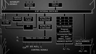
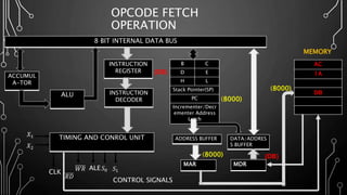
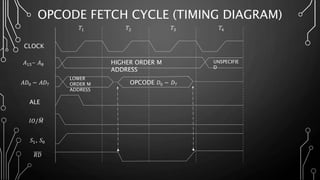

The document describes the opcode fetch cycle of the 8085 microprocessor. It contains a block diagram of the main components involved in the opcode fetch cycle, including the program counter, address latch, memory, and instruction register. It also includes a timing diagram that shows the clock signals and control signal timings during an opcode fetch cycle, such as the addressing of memory to retrieve the opcode. The opcode is then stored in the instruction register to be decoded by the microprocessor.