3. Necessity
• Since the wheels are provided with flanges
inside, so the direction of movement and
diversion of the vehicles to another track
controlled automatically by wheel flanges
rather than the driver.
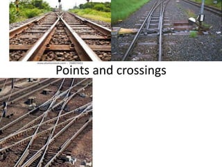
• special arrangements known as points and
crossings are provided
4. Necessity
• Points and crossings give flexibility of
movement by connecting one line to another.
• Help for imposing restrictions over turnouts to
retard the movements.
• Points and crossings to be properly deigned as
they are susceptible points for derailments
5. Parts of turnout
• Simplest combination of points and crossings which
enables one track either a branch line or a siding, to take of
from another track
Components
(i) A pair of points or switches (ABCD and EFPQ)
(ii) A pair of stock rails
(iii) A Vee crossing (GHIJ)
(iv) Two check rails
(v) Four lead rails
(vi) Switch tie plate or gauge tie chair and crossing tie plate
(vii)Studs or stops
(viii)Bearing plates, slide chairs, stretcher bars
(ix) Operating points-rods, cranks, levers
(x) For locking-locking box, lock bar, plunger bar etc.
6.
7.
8. Terms used in points and crossings
Facing direction: if some one stands at one of switch and looks towards
the crossing then the direction is called facing direction
Trailing direction: If someone stands at the crossing and looks towards
switches, then the direction is called as trailing direction.
Facing points of turnouts. Where train passes over the switches first
and then pass over the crossing. Important to specify when the
direction of movement of trains is reversed for facing direction.
Trailing points of turnouts: train passes over the crossing first and then
pass over the switches. Important to specify when the direction of
movement of trains is reversed for Trailing direction only.
Right-Hand and Left-Hand turnouts: a train from main track is diverted
to the right of main route in facing direction this diversion is Right-Hand
turnout and if a train from main track is diverted to the Left of main
route in facing direction this diversion is left-Hand turnout
Right hand and left hand switches: These ate termed as left hand or
right hand depending upon left or right when seen from the facing
direction.
10. Working principle of turnout
• One turnout provides facilities for turning of
vehicles from one direction only not both
directions
• Mainly contains a pair of switches (ABCD &
EFPQ) four lead rails(2 straight and 2 curved)
and two check rails and a crossing(GHIJ)
11. A pair of switches
• consists of a tongue rail and stock rail.
• Tongue rail is tapered having toe at one end and heel at
the other.
• Fixed at heel end to regular alignment and can be
moved about this point so that at one position a gap is
left with alignment and permits train to go along
straight alignment and in other position the toe fits
closely against the straight alignment and track thus
diverted to some other alignment.
• Position of straight alignment against which the tongue
rail fits is known as stock rail.
• Two such switches are fixed at to either rail, the tongue
rails move together so that the route can be set for the
mainline and the other for branch line.
12. A Crossing (one piece)
• Connected with the ordinary rails i.e lead rails to
permit two help in channelizing the wheels in
proper routes to permit rails to cross over each
other.
• Check rails are provided on the opposite sides of
the crossings to guide one wheel of the vehicle and
thus check tendency of the other wheel to climb
over the crossing.
• The point where point rail and splice rail meets is
known ad nose of crossing.
• Wing rail help in channelizing the wheels in their
proper routes
13. Points or Switches
• Switch consists of a stock rail and a tongue rail
• A set contains a left hand and a right hand
switch
Switches are tapered rails with the thicker end
known as the hell fixed to the main track
thinner end movable from which the train is
diverted from one route to another.
14. Components parts
• A pair of stock rails
• A pair of tongue rails
• Heel block or distance block
• Stretcher bars
• Switch tie plate or gauge tie plate
• Slide chairs or sliding plates
• Studs or stops
15.
16.
17. • A pair of stock rails: main rails of the track to which tongue rails
fit closely against them. made of rail steel and have same
dimensions as for other rails in the track (PQ is bent and AB is
straight)
• A pair of tongue rails:- Lie between two stock rails and are
tapered to point or tongue 0.64cm to 0.85cm wide. tongue rails
are supported on sliding plates and tongue rails is connected by
stretcher bars near the toe of switch so both the tongue rails
move through the same distance or gap and maintain the gauge.
This gap is known as throw of switch
• Requirements of tongue rail:
• Top and sides tapered and studs and stops strong enough
• Tongue rail 6mm high than stock rail at the centre
• Half thickness of tongue rail at toe should be closely fitted within
the stock rail.
18. • Heel block or Distance blocks: blocks inserted b/n heel of tongue rail
and stock rail. Made of cast iron and are used to provide a clear gap
foe wheel flange. Distance block same as heel block but used to
provide a flange way b/n the running rail and check rail.
• Stretcher bars: toes of both tongue rails are connected by means of
stretcher bars, so that each tongue moves though the same distance
or gap while changing the points. in general two or three bars are
used near and behind the toe. The length of the bar is such that the
distance between two toes is equal to gauge minus through of switch.
19.
20. • Switch tie plate (or gauge tie bar or plate) provided below the slide
chairs at the toe. Two butt straps known as stops at the ends are
provided to ensure definite location of slide chairs. used to hold the
track rigidly to the definite gauge at the toe of switches. Standard
sections are 25*1.25cm for BG and 22.5*0.9cm for M.G
• Slide Chairs: Special plates which are provided under the stock and
tongue rails. These help for the movement of tongue rail towards
and away from stock rail. On these stock rails remain fixed while
tongue rails are able to slide. Generally of 12.5cm to 15cm in length
increasing gradually towards heel.
• Studs or stops: fixed between the stock rails and tongue rails. Used
to prevent the lateral bending of the tongue rail and maintains
correct alignment when the wheels roll over the points made of
bent plate fitted to the web by means of stock rails and bolts
21. Important terms in turnouts
• Heel clearance or Heel divergence
• Flange way clearance
• Flange way depth
• Switch angle
• Throw of switch
• Flare
22. • Heel clearance or Heel divergence: Distance between the
running faces of the stock rail and gauge face of the tongue
rail when measured at the hell of the switch. it is kept equal to
flange way clearance plus tolerance for the wear plus the
width of head of rail. for B.G-13.7-13.3cm, for M.G -12.1-
11.7cm,N.G 9.8cm
23. • Flange way clearance: Distance between two adjacent
faces of the stock rail (running rail) and the check
(guard) rails. Provided as a clearance for fee
movement of wheel flanges (flange way) depends on
amount of wear and on number of crossings
• Flange way depth: Vertical distance b/n the top
surface of the running rail (stock) to the top surface of
heel –block used between the stock rail and check rail.
•
24.
25. • Switch angle: angle of witch divergence. Angle
between running faces of stock and tongue
rail. For smooth entry and movement should
be a minimum as possible for fast trains and
large for small moving and goods . Depends
on heel divergence and length of tongue rail
• Switch angle=Heel divergence
Length of tongue rail
26.
27. • Case1: when thickness of tongue rail at toe=0
and if d=Heel divergence and S= Length of
tongue rail
• Switch - sinα=d/s ; α =sin-1(d/s)
• CaseII when thickness of tongue rail at toe=t
then Sinα=d-t/s1 and α =sin-1(d-t/s1)
28. • Throw of switch: Distance through which the
toe and the tongue rail moves side ways (with
heel of tongue rail as the centre of rotation)
to provide a path for the desired direction
over a turnout.(9.5cm for B.G and 8.9cm for
N.G and M.G) in general 11.4cm is provided.
• Flare: Gradual (tapered ) widening of the
flange way which is formed by bending or
splaying the end of check rail or wing rail from
the gauge line. Provide to guide the path so
that the flange wheels enter and leave the
track smoothly.
29. Length of Tongue rails and stock rails
• For a given heel divergence, length of tongue
rail depends on switch angle.
• Carefully selected because use of long tongue
rail increase overall length of turn out whereas
short tongue rail will increase switch angle.
• To reduce the switch angle for a given heel
divergence and to maintain high speed s at
turnouts, length of tongue rail should be as
longer as possible and also jolting effect is also
reduced.
30. • Minimum length of tongue rail
• S= R tanα/2
• Standard lengths of tongue rails
• Gauge Number of crossing length of tongue rail
B.G 1 in 8.5 4.72
B.G 1 in 12 6.40
B.G 1 in 16 9.76
M.G 1 in 8.5 3.96
M.G 1in12 5.49
Note: length of stock rails should be more than the tongue rail to
avoid formation of rail joints near the toe as well as heel of
tongue rail .
31. Types of switches
• Sub switch
• Split switch fixation of heel
On Basis of cut
Loose Heel type or Articulated
type
Fixed Heel type or Spring type or
Flexible type
Under cut Switches
Over riding switches
Straight cut switches
32. • Loose heel type (or Articulated type ) switch . tongue rails are
joined to lead rails by means of fish plates.
• Two front bolts are kept loose to allow the throw of switch
and these bolts are kept tight when the tongue is open.
• Heel block , Anticreep devices and point lever box are used.
This is suitable for short length switches.
33. Fixed Heel type(or Spring type or Flexible type) switch
• an improvement over loose heel type switch.
• all the four bolts are tight when the tongue is closed.
• given quite satisfactory results when long tongue rails are
used. suitable with long tongue rails only.
34. Under cut switches.
• If the height of the stock and tongue is same, it is desirable to cut
of portion of flange at the foot of the stock rail so that the toe of
the tongue rail is accommodated (or housed) under the head of
the stock trail. Such switches are termed as undercut switches.
The disadvantage of this type of switch is that it becomes weak
because a flange portion is cut out. These switches are generally
used on narrow gauge lines
35. over riding switches
• separate rail sections of stock rails and tongue
rails are adopted.
• The stock rail of heavy section and tongue rail
of light section are used instead of cutting the
flange rather than weakening the stock rail
• The tongue rail in this type rides over the flange
of the stock rail.
• A compound fish plate at the hell is necessary
to connect it to the lead rail. This is generally
used for B.G. and M.G. tracks.
• A modified form of over riding switch
commonly used in U.S.A In this tongue rail is
kept higher by 6mm than stock rail which may
develop oscillations and also stock rail
maintains full section and Tongue rail is duly
supported on the flange of stock rail. The false
flange does not penetrate the head of stock rail
as tongue rail is kept higher to stock rail.
36. Straight cut switches
• Tongue rail is cut in straight in
the line with the stock rail.
• Done to increase the thickness
of tongue rail and increases the
strength.
• Stock rail is joggled (15m)near
the toe of switch during
manufacture to fit the toe or
flush with the stock rail. used
for B.H rails
• As gauge increases straight cut
are provided for facing and
under cut are provided for
trailing direction.
37. crossing
• Also called frog, A device which provides two
flange wheels through which the wheels of
the flanges may move, when two rails
intersect each other at an angle.
• The flanged wheels of the train jump over the
gap from throat to nose of crossing and to
check the wheel flanges are guided by the use
of check rails inside the running rails.
38. Components parts of crossing
• A crossing or Vee Piece
• Point and splice rails
• Wing rails
• Check rails
• Chairs at crossing, at toe and at heel
• Blocks at throat, at nose, at heel and distance
block
• At times packing below the wing rails at toe
and throat.
39. Requirements and characteristics of a good crossing
• Assembly should be rigid to stand against severe vibrations( can be
achieved by use of sole plate at turned bolts for connecting the point
and splice rails and riveting the foot flanges to the sole plate.)
• Wear on parts of wing rails opposite to and also of the nose should be
minimum (can be achieved by using high alloy steel)
• Crossing body to be rigid as possible and as long as practicable( can be
achieved by extending the flange ,ramping the wing rails by 3mm to
6mm and us of distance blocks closely touching the web and marinating
perfect gauge)
• Nose should have some thickens. Generally varies from 6mm to 18mm.
• Distance b/n theoretical nose of crossing and actual nose of crossing for
practical purposes is equal to nose thickness x Number of crossing,
40. Types of crossings
• 1. On basis of shape
Acute angle crossing or v crossing or frog
Obtuse angle or diamond crossing
Square crossing
2. On the basis of Assembly of crossing
Spring or movable wing crossing
Ramped crossing
41. Acute angle crossing
• Generally widely used
• crossing is obtained when a left-hand rail of one track crosses a right –
hand rail of another track.
• angle of intersection is acute angle, is termed as acute angle crossing.
• Mainly consists of point , splice rails, wing rails and check rails. Long rails
carry the wheels
42. • Point and splice rails: An acute angle either by a point rail and a splice rail
or combination of two point rails. Made of special steel.
•A pair of wing rails: These are bent at the ends . One end of the wing
rails is connected to lead rails where as the other end is flared. This
flaring is done to facilitate the entry and exit of flange wheels to the gap
•A pair of check rails: Subsidiary rails parallel to running rails flared at
end for guiding the wheel flanges. Provides on opposite sides of crossing
angle to guide wheel flanges, prevent wear and rocking of wheels and to
prevent derailment at level crossings
43. Obtuse angle crossing
• crossing is obtained when a left-hand rail of one track crosses
a right –hand rail of another track or vice versa at an obtuse
angle
• In Diamond crossing these are generally used.
• Long rails don’t carry the wheels rather act as check rails.
44. Square crossing
• When two straight tracks cross each other at right
angles gives rise to diamond crossing
• Must be avoided on main lines as there is heavy wear
due to dynamic loads
45. Spring or movable crossing
• One wing rail movable is held against the Vee of the crossing with a
strong helical spring.
• Makes main track continuous
• Useful for high speed on main tack and light speeds on branch track
• Improper maintenance leads to frequent accidents not favorable in
India
46. Ramped crossing
• Used in case complicated layout at an yard for heavy load
with light speed.
• Throat to nose clearance is negotiated by use of special
manganese alloy steel blocks
• Wheel flanges roll over the distance extending from little
beyond the nose. top level of blocks is arranged that the
tread of the wheel is taken off the table by wheel flange
riding the blocks.
• The entire wheel load comes on to flanges
47. Important Terms used in Crossings
• Theoretical and Actual nose of crossing:
• Point rail is note defined to a sharp point as it breaks off
under the application of loads.
• Blunt nose is provided.
• Thickness of blunt nose is equal to web of rail
• Varies from 0.6cm to 1.9cm with increasing section.
• The sharp imaginary point where the two gauge faces in case
of acute angle crossing or the gauge face and sloping obtuse
angle crossing would meet is known as true or theoretical
nose of crossing (T.N.C). All the calculations are made from
theoretical nosing
The dis b/n T.N.C and A.N.C dta
dta =N×t
N=Number of crossings
t=thickness of the nose of the crossing
48. Number of crossing and angle of
crossing:
• Acute angle crossings are designated by either
angle that the gauge faces make with each
other or generally by N
• N=The spread at the leg of crossing
• The length of crossing at T.N.C
49. Methods to determine the number of crossings
• Right angle or Cole’s method: (Standard method adopted by Indian railways
From fig.
tan α =1/N………………… (1a) (Angle of crossing)
cotα =N…………………… (1b)(Number of crossing)
ab: point rail
ac: another point rail or splice rail
bc: denotes spread at the leg=unity=1
a
b
c
1
N
α
T.N.C
50. Centre line method( adopted in U.S.A and U.K)
• tan α/2=1/2/N=1/2N…………………… (2a) (Angle of crossing)
• cot α/2=2N
• N=1/2cot α/2……………………………. (2b) (Number of crossing)
a
N
α/2
α/2
b
c
α
T.N.C
1
51. Isosceles triangle method
(important for layouts of tramways)
• From the fig N is taken along one side of isosceles triangle, hence
• Sin α/2=1/2/N=1/2N…………………… (3a) (Angle of crossing)
• cosec α/2=2N
• N=1/2cosec α/2…………………………….(3b) (Number of crossing)
a
N
α/2
α/2
b
c
α
T.N.C
1
Note ; Since α is very small the difference of N calculated by various
formulas is less
More the angle of crossing less the permissible speed and vice versa
Permissible speed in km.p.h is less than 2.4xnumber of crossings
52. crossing use
1 in 6 Symmetrical splits
1 in 8 1/2 Station yards, space restricted,
low speed, sharp turnouts
1 in 12 Station yards of main lines on
flat turnouts
1 in 16 High speed on B.G and M.G
53. Design Calculations of turnout
• Turn out after branching off from main track, may
run in to various directions of which running parallel
to original track is common .
• The design calculations of various turnouts are based
on following factors
– Method of calculating various leads
– Method employed for crossing angle
– Type of tongue rail used
– Kink: Lateral movement of the ends of the rails
out of its original position due to several reasons
causes such a loose joints, defective gauges etc
called as kinks.
54. Notations used in design calculations
• CL=Curve lead ( Distance between T.N.C and the tangent point
“T” measured along the length of the main track)
• SL=Switch lead (Distance between tangent point “T” and heel
of switch measured along the length of the main track)
• L=Lead or crossing lead (Distance between T.N.C and heel of
switch measured along the length of the main track
• Hence CL=SL+L
• L=CL-SL
• .
55. • Let β- Angle of switch= angle b/n the gauge faces of
switch rail and stock rail.
• α = Angle of crossing
• d= Heel divergence or clearance
• Ro= Radius of outer curve of turnout
• R= radius of center line of turn out
• G=Gauge of track
• N=Number of crossings
• D=distance between T.N.C and tangent point of
crossing curve
56.
57. Method –I Important features
• All three leads are calculated.
• Crossing angle is calculated or usage of right
angle method
• In this a crossing curve is considered from an
imaginary tangent point ahead of actual toe of
switch and end at T.N.C hence three kinks are
formed
• One at toe ( due to straight tongue rail) other
at heel of switch( tongue rail is not tangential
to curve), other at toe of crossing( curve is
carried theoretically up to T.N.C but actually is
straight)
58. • (1) Curve lead (CL)
from triangle TBC ,
tan α/2 = BC/TB=G/C.L.
C.L=G cot α/2 --------------------(1)
From fig Cl2=G(2Ro-G)=2GRo (neglecting G2)
Also CL=BE+ET=BE+EC(:ET=EC)
G cot α +G Cosec α from triangle BEC
G( (1+cot2 α)+cot α)
G( 1+N2+G.N)=2GN (N=number of crossings)
59. R-Radius
From triangle OCD
Sin α=DC/OC=TB/ Ro=CL/Ro
Ro=CL/ Sin α
R=Ro-G/2
Ro=TD +DO=G+CL cot α=G+2GNxN
Switch lead
Sl2= d(2Ro-d)
SL= d(2Ro-d)
Lead or crossing lead)=C.L-S.L=2GN - (2Roxd
Heel divergence-d=( S.L)2/2Ro
60. Method II
• Only the cross lead ”L” is calculated
• Curve is tangential to the tongue rail and
springs from the heel of switch and ends at
T.N.C
• A kink which is formed at the heel of the
switch is removed
61.
62. Design calculations
If G (Gauge), d (heel divergence), α( angle of crossing), β- Angle
of switch then
(1) Lead or crossing lead (L):
From triangle TDC,
tan(α+ β)/2=(G - d) / L
L=(G-d)/ tan (α+ β)/2=(G-d) cot (α+ β)/2
(2) R-Radius
‹COF= (α-β)/2
Where ‘o’ is the centre of the curve
Sin((α-β)/2 = CF/Ro=CT/2Ro=TD/ Sin((α+ β)/2 x(1/2Ro)
=G-d/(2Ro Sin((α+ β)/2)
Ro=G-d/(2Sin((α+ β)/2)sin(((α-β)/2 )=(G-d)/ (Cos α –Cos β )
R=(Ro-G/2)
63. Method-III
• Similar to method 2 but straight length at
crossing is provided
• One end of the curve is tangential to the
tongue rail and springs up from the heel of the
switch and the other spring up from the toe of
crossing and is tangential to the straight
length of crossing.
• One kink at toe of switch is only left
64.
65. Let the straight length of arm at crossing x=T1C
Radius R: With the given values of G,D, α, β and x,
From triangle TPT1
Sin PT1T=TP/TT1
TT1=TPcosecPT1T= TP cosec (α+ β)/2
TF=T1F=TT1= 1/2 TP cosec (α+ β)/2
Also from triangle OFT1 ,where ‘O” is the curve centre.
Sin TOF =T1F/OT1 =T1F/Ro
Ro=T1F/ Sin TOF =T1F Cosec (((α-β)/2 =1/2 TP cosec (α+ β)/2 Cosec (α-
β)/2
=TP/ (Cos β –Cos α )=G1/(Cos β – Cos α )
G1 =TP=TS-PS=TL-T1N= G-d- x Sin α
Ro= G-d- x Sin α/(Cos β – Cos α )
R=Ro-G/2