
Recommended
More Related Content
Similar to Module 3 Lab Determining Beta for BJTsWire the circuit shown.docx
Similar to Module 3 Lab Determining Beta for BJTsWire the circuit shown.docx (20)
More from raju957290
More from raju957290 (20)
Recently uploaded
Recently uploaded (20)
Module 3 Lab Determining Beta for BJTsWire the circuit shown.docx
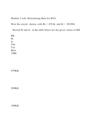
- 1. Module 3 Lab: Determining Beta for BJTs Wire the circuit shown, with Rc = 470 Ω and Q = 2N3904 · Record Ib and Ic in the table below for the given values of RB RB Ib Ic Vbe Vce Beta 1MΩ 470KΩ 200KΩ 100KΩ
- 2. 47KΩ · Return the RB value to 470KΩ, (A) Squeeze the transistor between your fingers to raise the case temperature, record any change in collector current _______ (B) Put a piece of ice in a plastic bag and hold it on the transistor to reduce the case temperature, record any change in collector current __________ · Describe your perception of the relationship between Beta and case temperature. · Describe the behavior of Beta vs Ic Written Assignment 4 Answer all of the following questions/problems and submit them to your mentor. Questions: 1. In a transistor circuit, the two extreme ends of the loadline are called: 2. When used as an amplifier, the transistor is usually biased in the region called the _______________ region. 0. The Q point for an amplifier is identified as _______ & _______ , which together determine the power dissipated in the
- 3. transistor. Problems: 1. For the circuit shown, VBB = +10v, Vcc = +30v, RB = 470kΩ, Rc = 6kΩ Calculate the operating point for the circuit shown for a Beta value of 90 and for a Beta value of 130. 2. For the circuit shown, Vcc = -10v, R1 = 10kΩ, R2 = 2.2kΩ, Rc = 3.6kΩ, RE = 1kΩ. Calculate the operating point for the circuit shown. Use IB = IC / Beta and calculate IB for Beta = 90.
- 4. Module 4 Lab: AC Riding on DC R1 = 2.2KΩ R2 = 4.7KΩ C = 0.1uF Vdc = +5v Vac = 3v peak f = 1KHz · Use superposition to calculate the DC voltage at point X VDC = ______ · Use superposition to calculate the AC (peak) voltage at point X VAC = ______ · Sketch what you think the scope will show at X: · Wire the circuit and connect a scope probe at X, be sure to DC couple the input and set the ground level at the bottom of the scope display, then sketch the results.
- 5. Written Assignment 5 Answer all of the following questions/problems and submit them to your mentor. Questions: 1. Describe what is meant by the voltage gain of an amplifier. 0. What is the primary purpose of coupling capacitors in transistor amplifiers? Problems: 1. If the input voltage to an amplifier is 50mV and the resulting output voltage is 3V, calculate the voltage gain. 0. A transistor is biased with IE = 5mA. Calculate r’e 0. For the circuit shown, calculate: a. The input resistance at the base of the transistor. a. The input resistance of the amplifier. a. The voltage gain. 0. If a circuit requires a capacitor to give good coupling at 200Hz and the resistance the capacitor is connected to is 3Kohms, what value capacitor is needed?
- 6. Module 5 Lab: Amplifier Gain and Comparing Constant Bias to VDB Part I (A) Wire the circuit shown. [ you will determine the β value from DC measurements] R1 = 20KΩ, R2 = 5MΩ ( two 10MΩ in parallel ), R3 = 20KΩ, C = 0.1uF, use 2N3904 for the transistor · Measure D.C. Vc = _____ and Vbe = _____ · Calculate Ic = ( Vcc - Vc )/ Rc = ______ and IB = ( Vcc - Vbe )/ RB = _____ then β = _____ (a) Verify that Rbe = Rin base = β re’ · Measure A.C. voltages vc = ____ vbe = _____ · Calculate ib = ( 10mV – vbe ) / 20 Kohms = _____ · Calculate ic = vc / 20kΩ = _____ calculate βac = ic / ib = ______ · Rbe = vbe / ib = _____ re’ = 25mV/ IE = _______ ic = βac ib = ____ · Also calculate Rbe = βac re’ = _____ does this check with the value above?
- 7. (B) To show the effects of changing beta on the Q point. · Hold your finger on the case to raise the temperature and the Q point should change (Vc goes down) due to the fact that beta goes up as temperature goes up causing an increase in Ic. · With a piece of ice in plastic bag, hold it on the transistor to cool it; this should cause beta to decrease. The Q point will change again ( Vc goes up ). Part II To show the advantage of VDB over CCB · Wire the VDB circuit shown. The transistor beta value was determined in part A. · Measure [ D.C.] VB = ____ and VE = _____ · Calculate IE = _____ and re’ = _____ · Measure [ A.C. ] vin = _____ and vo = ____ · Now calculate voltage gain by two methods: . Av = vc / vin = ______ and Av = Rc / re’ = _______. . Do these two values match? · Next hold your finger on the transistor and notice that the Q point does not change. Change the transistor and again note that the Q point stays constant. Written Assignment 6 Answer all of the following questions/problems and submit them to your mentor.
- 8. Questions: 1. For each circuit shown, indicate if it is CE, CB or CC amplifier. Figure A Figure B Figure C 0. Show two transistors connected as a Darlington amplifier. If one transistor has a beta of 25 and the other has a beta of 60, calculate the beta value of this combination. Problems: 1. For the amplifier shown, if beta = 150 (a) Calculate the input impedance at the base (b) Calculate the input impedance of the stage. 0. Shown here is a frequency response curve for an amplifier. ESTIMATE the following: (a) What is the high cutoff frequency ? (b) What is the low cutoff frequency? (c) What is the bandwidth? 0. An amplifier has a gain of 500, what is the dB gain? 0. A three stage amplifier system has dB gains of 15dB, 32dB and 6db. What is the overall gain of the system in dB?
- 9. Module 6 Lab: Class A BroadBand Amplifier Wire the circuit shown: R1 = 68KΩ, R2 = 10KΩ, R3 = 10KΩ, R4 = 200Ω ( two 100Ω in series ) , R5 = 2.2KΩ, C1 = 0.1uF, C2 = 0.1 uF Q1 = 2N3904 · Set the sig. Gen to 50mv RMS. With frequency equal to 10KHz. · Record vo for the frequencies listed. vo f ( KHz) 10KHz 25 KHz 50 KHz 100 KHz 500 KHz 1MHz 2 MHz 3MHz Calc Av · Plot Av versus frequency on semi log paper.