2. H. El-Dessouky et al. / Chemical Engineering and Processing 41 (2002) 551–561552
“ Ejectors have very low thermal efficiency.
Applications of jet ejectors include refrigeration, air
conditioning, removal of non-condensable gases, trans-
port of solids and gas recovery. The function of the jet
ejector differs considerably in these processes. For ex-
ample, in refrigeration and air conditioning cycles, the
ejector compresses the entrained vapor to higher pres-
sure, which allows for condensation at a higher temper-
ature. Also, the ejector entrainment process sustains the
low pressure on the evaporator side, which allows
evaporation at low temperature. As a result, the cold
evaporator fluid can be used for refrigeration and cool-
ing functions. As for the removal of non-condensable
gases in heat transfer units, the ejector entrainment
process prevents their accumulation within condensers
or evaporators. The presence of non-condensable gases
in heat exchange units reduces the heat transfer effi-
ciency and increases the condensation temperature be-
cause of their low thermal conductivity. Also, the
presence of these gases enhances corrosion reactions.
However, the ejector cycle for cooling and refrigeration
has lower efficiency than the MVC units, but their
merits are manifested upon the use of low grade energy
that has limited effect on the environment and lower
cooling and heating unit cost.
Although the construction and operation principles
of jet ejectors are well known, the following sections
provide a brief summary of the major features of
ejectors. This is necessary in order to follow the discus-
sion and analysis that follow. The conventional steam
jet ejector has three main parts: (1) the nozzle; (2) the
suction chamber; and (3) the diffuser (Fig. 1). The
nozzle and the diffuser have the geometry of converg-
ing/diverging venturi. The diameters and lengths of
various parts forming the nozzle, the diffuser and the
suction chamber, together with the stream flow rate and
properties, define the ejector capacity and performance.
The ejector capacity is defined in terms of the flow rates
of the motive steam and the entrained vapor. The sum
of the motive and entrained vapor mass flow rates gives
the mass flow rate of the compressed vapor. As for the
ejector performance, it is defined in terms of entrain-
ment, expansion and compression ratios. The entrain-
ment ratio (w) is the flow rate of the entrained vapor
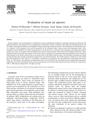
Fig. 1. Variation in stream pressure and velocity as a function of location along the ejector.
3. H. El-Dessouky et al. / Chemical Engineering and Processing 41 (2002) 551–561 553
divided by the flow rate of the motive steam. As for the
expansion ratio (Er), it is defined as the ratio of the
motive steam pressure to the entrained vapor pressure.
The compression ratio (Cr) gives the pressure ratio of
the compressed vapor to the entrained vapor.
Variations in the stream velocity and pressure as a
function of location inside the ejector, which are shown
in Fig. 1, are explained below:
“ The motive steam enters the ejector at point (p) with
a subsonic velocity.
“ As the stream flows in the converging part of the
ejector, its pressure is reduced and its velocity in-
creases. The stream reaches sonic velocity at the
nozzle throat, where its Mach number is equal to one.
“ The increase in the cross section area in the diverging
part of the nozzle results in a decrease of the shock
wave pressure and an increase in its velocity to
supersonic conditions.
“ At the nozzle outlet plane, point (2), the motive steam
pressure becomes lower than the entrained vapor
pressure and its velocity ranges between 900 and 1200
m/s.
“ The entrained vapor at point (e) enters the ejector,
where its velocity increases and its pressure decreases
to that of point (3).
“ The motive steam and entrained vapor streams may
mix within the suction chamber and the converging
section of the diffuser or it may flow as two separate
streams as it enters the constant cross section area of
the diffuser, where mixing occurs.
“ In either case, the mixture goes through a shock
inside the constant cross section area of the diffuser.
The shock is associated with an increase in the
mixture pressure and reduction of the mixture veloc-
ity to subsonic conditions, point (4). The shock
occurs because of the back pressure resistance of the
condenser.
“ As the subsonic mixture emerges from the constant
cross section area of the diffuser, further pressure
increase occurs in the diverging section of the dif-
fuser, where part of the kinetic energy of the mixture
is converted into pressure. The pressure of the emerg-
ing fluid is slightly higher than the condenser pres-
sure, point (c).
Summary for a number of literature studies on ejector
design and performance evaluation is shown in Table 1.
The following outlines the main findings of these studies:
“ Optimum ejector operation occurs at the critical
condition. The condenser pressure controls the loca-
tion of the shock wave, where an increase in the
condenser pressure above the critical point results in
a rapid decline of the ejector entrainment ratio, since
the shock wave moves towards the nozzle exit. Oper-
ating at pressures below the critical points has negli-
gible effect on the ejector entrainment ratio.
“ At the critical condition, the ejector entrainment ratio
increases at lower pressure for the boiler and con-
denser. Also, higher temperature for the evaporator
increases the entrainment ratio.
“ Use of a variable position nozzle can maintain the
optimum conditions for ejector operation. As a re-
sult, the ejector can be maintained at critical condi-
tions even if the operating conditions are varied.
“ Multi-ejector system increases the operating range
and improves the overall system efficiency.
“ Ejector modeling is essential for better understanding
of the compression process, system design and perfor-
mance evaluation. Models include empirical correla-
tions, such as those by Ludwig [1], Power [2] and
El-Dessouky and Ettouney [3]. Such models are lim-
ited to the range over which it was developed, which
limits their use in investigating the performance of
new ejector fluids, designs or operating conditions.
Semi-empirical models give more flexibility in ejector
design and performance evaluation [4,5]. Other ejec-
tor models are based on fundamental balance equa-
tions [6].
This study is motivated by the need for a simple
empirical model that can be used to design and evaluate
the performance of steam jet ejectors. The model
is based on a large database extracted from several
ejector manufacturers and a number of experimental
literature studies. As will be discussed later, the model
is simple to use and it eliminates the need for iterative
procedures.
2. Mathematical model
The review by Sun and Eames [7] outlined the devel-
opments in mathematical modeling and design of jet
ejectors. The review shows that there are two basic
approaches for ejector analysis. These include mixing of
the motive steam and entrained vapor, either at constant
pressure or at constant area. Design models of stream
mixing at constant pressure are more common in litera-
ture because the performance of the ejectors designed by
this method is more superior to the constant area
method and it compares favorably against experimental
data. The basis for modeling the constant pressure
design procedure was initially developed by Keenan [6].
Subsequently, several investigators have used the model
for design and performance evaluation of various types
of jet ejectors. This involved a number of modifications
in the model, especially losses within the ejector and
mixing of the primary and secondary streams. In this
section, the constant pressure ejector model is devel-
oped. The developed model is based on a number of
literature studies [8–11].
The constant pressure model is based on the following
assumptions:
4. H. El-Dessouky et al. / Chemical Engineering and Processing 41 (2002) 551–561554
Table 1
Summary of literature studies on ejector design and performance
Boiler, evaporator and condenserFluidReference Conclusion
temperature (°C)
60–100; 5–18; 40–50[19] Basis for refrigerant selection for solar system, system performanceR-113
increased with increasing boiler and evaporator temperatures and
decreasing condenser temperature.
R-113; R-114;[20] 80–95; 5–13; 25–45 Comparison of ejector and refrigerant performance. Dry, wet and
isentropic fluids. Wet fluid damage ejectors due phase change duringR-142b; R-718
isentropic expansion. R-113 (dry) has the best performance and
R142b (wet) has the poorest performance.
86; −8; 30[21,22] Increase in ejector performance using mechanical compressionR-114
booster.
120–140; 5–10; 30–65Water Choking of the entrained fluid in the mixing chamber affects system[8]
performance. Maximum COP is obtained at the critical flow
condition.
120–140; 5–10; 30–60[13] Effect of varying the nozzle position to meet operating condition.Water
Increase in COP and cooling capacity by 100%.
70–100; 6–25; 42–50[23] Entrainment ratio is highly affected by the condenser temperatureR-113
especially at low evaporator temperature.
82.2–182.2; 10; 43.3 Entrainment ratio is proportional to boiler temperature.R-11[24]
R-114 90; 4; 30 Combined solar generator and ejector air conditioner. More efficient[25,26]
system requires multi-ejector and cold energy storage (cold storage in
either phase changing materials, cold water or ice).
[27] −15; 30 Modeling the effect of motive nozzle on system performance, inR-134A
which the ejector is used to recover part of the work that would be
lost in the expansion valve using high-pressure motive liquid.
[28] 100–165; 10; 30–45 Combined solar collector, refrigeration and seawater desalinationWater
system. Performance depends on steam pressure, cooling water
temperature and suction pressure.
Water[4] Developed a new ejector theory in which the entrained fluid is
choked, the plant scale results agree with this theory. Steam jet
refrigeration should be designed for the most often prevailing
conditions rather than the most severe to achieve greater overall
efficiency.
Water[29] – Model of multistage steam ejector refrigeration system using annular
ejector in which the primary fluid enters the second stage at annular
nozzle on the sidewall. This will increase static pressure for
low-pressure stream and mixture and reduce the velocity of the
motive stream and reduce jet mixing losses shock wave formation
losses.
R11; R113;[24] 93.3; 10; 43.3 Measure and calculate ejector entrainment ratio as a function of
boiler, condenser and evaporator temperatures. Entrainment ratioR114
decreases for off design operation and increases for the two stage
ejectors.
[30] R113; R114; 120–140; 65–80 Effect of throat area, location of main nozzle and length of the
R142b constant area section on backpressure, entrainment ratio and
compression ratio.
Mathematical model use empirical parameters that depend solely on[5]
geometry. The parameters are obtained experimentally for various
types of ejectors.
5; −12, −18; 40[31] Combined ejector and mechanical compressor for operation ofR134a
domestic refrigerator-freezer increases entrainment ratio from 7 to
12.4%. The optimum throat diameter depends on the freezer
temperature
80; 5; 30[9] Performance of HR-123 is similar to R-11 in ejector refrigeration.R11; HR-123
Optimum performance is achieved by the use of variable geometry
ejector when operation conditions change.
5. H. El-Dessouky et al. / Chemical Engineering and Processing 41 (2002) 551–561 555
1. The motive steam expands isentropically in the
nozzle. Also, the mixture of the motive steam and
the entrained vapor compresses isentropically in the
diffuser.
2. The motive steam and the entrained vapor are
saturated and their velocities are negligible.
3. Velocity of the compressed mixture leaving the ejec-
tor is insignificant.
4. Constant isentropic expansion exponent and the
ideal gas behavior.
5. The mixing of motive steam and the entrained
vapor takes place in the suction chamber.
6. The flow is adiabatic.
7. Friction losses are defined in terms of the isentropic
efficiencies in the nozzle, diffuser and mixing
chamber.
8. The motive steam and the entrained vapor have the
same molecular weight and specific heat ratio.
9. The ejector flow is one-dimensional and at steady
state conditions.
The model equations include the following:
“ Overall material balance
mp +me =mc (1)
where m is the mass flow rate and the subscripts c, e
and p, define the compressed vapor mixture, the
entrained vapor and the motive steam or primary
stream.
“ Entrainment ratio
w=me/mp (2)
“ Compression ratio
Cr=Pc/Pe (3)
“ Expansion ratio
Er=Pp/Pe (4)
“ Isentropic expansion of the primary fluid in the
nozzle is expressed in terms of the Mach number of
the primary fluid at the nozzle outlet plane
Mp2
=
'2pn
k−1
Pp
P2
(k−1/k)
−1
n (5)
where M is the Mach number, P is the pressure and
k is the isentropic expansion coefficient. In the above
equation, pn is the nozzle efficiency and is defined as
the ratio between the actual enthalpy change and the
enthalpy change undergone during an isentropic
process.
“ Isentropic expansion of the entrained fluid in the
suction chamber is expressed in terms of the Mach
number of the entrained fluid at the nozzle exit plane
Me2
=
' 2
k−1
Pe
P2
(k−1/k)
−1
n (6)
“ The mixing process is modeled by one-dimensional
continuity, momentum and energy equations. These
equations are combined to define the critical Mach
number of the mixture at point 5 in terms of the
critical Mach number for the primary and entrained
fluids at point 2
M4*=
Mp2
* +wMe2
*
Te/Tp
(1+w)(1+wTe/Tp)
(7)
where w is the entrainment ratio and M* is the ratio
between the local fluid velocity to the velocity of
sound at critical conditions.
“ The relationship between M and M* at any point in
the ejector is given by this equation
M*=
' M2
(k+1)
M2
(k−1)+2
(8)
Eq. (8) is used to calculate Me2
* , Mp2
* , M4
“ Mach number of the mixed flow after the shock
wave
M5 =
M4
2
+
2
(k−1)
2k
(k−1)
M4
2
−1
(9)
“ Pressure increase across the shock wave at point 4
P5
P4
=
1+kM4
2
1+kM5
2
(10)
In Eq. (10) the constant pressure assumption implies
that the pressure between points 2 and 4 remains
constant. Therefore, the following equality con-
straint applies P2 =P3 =P4.
“ Pressure lift in the diffuser
Pc
P5
=
pd(k−1)
2
M5
2
+1
n(k/k−1)
(11)
where pd is the diffuser efficiency.
“ The area of the nozzle throat
A1 =
mp
Pp
'RTp
kpn
k+1
2
(k+1)/(k−1)
(12)
“ The area ratio of the nozzle throat and diffuser
constant area
A1
A3
=
Pc
Pp
1
(1+w)(1+w(Te/Tp))
1/2
P2
Pc
1/k
1−
P2
Pc
(k−1)/k
1/2
2
k+1
1/(k−1)
1−
2
k+1
1/2
(13)
6. H. El-Dessouky et al. / Chemical Engineering and Processing 41 (2002) 551–561556
“ The area ratio of the nozzle throat and the nozzle
outlet
A2
A1
=
' 1
Mp2
2
2
(k+1
1+
(k−1)
2
Mp2
2 (k+1)/(k−1)
(14)
3. Solution procedure
Two solution procedures for the above model are
shown in Fig. 2. Either procedure requires iterative
calculations. The first procedure is used for system
design, where the system pressures and the entrainment
ratio is defined. Iterations are made to determine the
pressure of the motive steam at the nozzle outlet (P2) that
gives the same back pressure (Pc). The iteration sequence
for this procedure is shown in Fig. 2(a) and it includes
the following steps:
“ Define the design parameters, which include the en-
trainment ratio (w), the flow rate of the compressed
vapor (mc) and the pressures of the entrained vapor,
compressed vapor and motive steam (Pe, Pp, Pc).
“ Define the efficiencies of the nozzle and diffuser (pn,
pd).
“ Calculate the saturation temperatures for the com-
pressed vapor, entrained vapor and motive steam,
which include Tc, Tp, Te, using the saturation temper-
ature correlation given in the appendix.
“ As for the universal gas constant and the specific heat
ratio for steam, their values are taken as 0.462 and 1.3.
“ The flow rates of the entrained vapor (me) and motive
steam (mp) are calculated from Eqs. (1) and (2).
“ A value for the pressure at point 2 (P2) is estimated
and Eqs. (5)–(11) are solved sequentially to obtain the
pressure of the compressed vapor (Pc).
“ The calculated pressure of the compressed vapor is
compared to the design value.
“ A new value for P2 is estimated and the previous step
is repeated until the desired value for the pressure of
the compressed vapor is reached.
Fig. 2. Solution algorithms of the mathematical model. (a) Design procedure to calculate area ratios. (b) Performance evaluation to calculate w.
7. H. El-Dessouky et al. / Chemical Engineering and Processing 41 (2002) 551–561 557
“ The ejector cross section areas (A1, A2, A3) and the
area ratios (A1/A3 and A2/A1) are calculated from
Eqs. (12)–(14).
The second solution procedure is used for perfor-
mance evaluation, where the cross section areas and the
entrainment and motive steam pressures are defined.
Iterations are made to determine the entrainment ratio
that defines the ejector capacity. The iteration sequence
for this procedure is shown in Fig. 2(b) and it includes
the following steps:
“ Define the performance parameters, which include
the cross section areas (A1, A2, A3), the pressures of
the entrained vapor (Pe) and the pressure of the
primary stream (Pp).
“ Define the efficiencies of the nozzle and diffuser (pn,
pd).
“ Calculate the saturation temperatures of the primary
and entrained streams, Tp and Te, using the satura-
tion temperature correlation given in the appendix.
“ As for the universal gas constant and the specific
heat ratio for steam, their values are taken as 0.462
and 1.3.
“ Calculate the flow rate of the motive steam and the
properties at the nozzle outlet, which include mp, P2,
Me2, Mp2. These are obtained by solving Eqs. (5),
(6), (12) and (14).
“ An estimate is made for the entrainment ratio, w.
“ This value is used to calculate other system parame-
ters defined in Eqs. (7)–(11), which includes Me2
* ,
Mp2
* , M4*, M4, M5, P5, Pc.
“ A new estimate for w is obtained from Eq. (13).
“ The error in w is determined and a new iteration is
made if necessary.
“ The flow rates of the compressed and entrained
vapor are calculated from Eqs. (1) and (2).
4. Semi-empirical model
Development of the semi-empirical model is thought
to provide a simple method for designing or rating of
steam jet ejectors. As shown above, solution of the
mathematical model requires an iterative procedure.
Also, it is necessary to define values of pn and pd. The
values of these efficiencies widely differ from one study
to another, as shown in Table 2. The semi-empirical
model for the steam jet ejector is developed over a wide
range of operating conditions. This is achieved by using
three sets of design data acquired from major ejector
manufacturers, which includes Croll Reynolds, Graham
and Schutte–Koerting. Also, several sets of experimen-
tal data are extracted from the literature and are used
in the development of the empirical model. The semi-
empirical model includes a number of correlations to
calculate the entrainment ratio (w), the pressure at the
nozzle outlet (P2) and the area ratios in the ejector
Table 2
Examples of ejector efficiencies used in literature studies
pnReference pmpd
0.9[27] 0.75
[32] 0.8 0.8
[33] 0.85 0.85
0.7–10.7–1[31]
[10] 0.8–1 0.8–1
0.85–0.98[24] 0.65–0.85
0.950.850.85[8]
0.75[34] 0.9
(A2/A1) and (A1/A3). The correlation for the entrain-
ment ratio is developed as a function of the expansion
ratio and the pressures of the motive steam, the en-
trained vapor and the compressed vapor. The correla-
tion for the pressure at the nozzle outlet is developed as
a function of the evaporator and condenser pressures.
The correlations for the ejector area ratios are defined
in terms of the system pressures and the entrainment
ratio. Table 3 shows a summary of the ranges of the
experimental and the design data. The table also in-
cludes the ranges for the data reported by Power [12].
A summary of the experimental data, which is used
to develop the semi-empirical model is shown in Table
4. The data includes measurements by the following
investigators:
“ Eames et al. [8] obtained the data for a compression
ratio of 3–6, expansion ratio 160–415 and entrain-
ment ratio of 0.17–0.58. The measurements are ob-
tained for an area ratio of 90 for the diffuser and the
nozzle throat.
“ Munday and Bagster [4] obtained the data for a
compression ratio of 1.8–2, expansion ratio of 356–
522 and entrainment ratio of 0.57–0.905. The mea-
surements are obtained for an area ratio of 200 for
the diffuser and the nozzle throat.
“ Aphornratana and Eames [13] obtained the data for
a compression ratio of 4.6–5.3, expansion ratio of
309.4 and entrainment ratio of 0.11–0.22. The mea-
surements are obtained for an area ratio of 81 for
the diffuser and the nozzle throat.
“ Bagster and Bresnahan [14] obtained the data for a
compression ratio of 2.4–3.4, expansion ratio of
165–426 and entrainment ratio of 0.268–0.42. The
measurements are obtained for an area ratio of 145
for the diffuser and the nozzle throat.
“ Sun [15] obtained the data for a compression ratio of
2.06–3.86, expansion ratio of 116–220 and entrain-
ment ratio of 0.28–0.59. The measurements are ob-
tained for an area ratio of 81 for the diffuser and the
nozzle throat.
“ Chen and Sun [16] obtained the data for a compres-
sion ratio of 1.77–2.76, expansion ratio of 1.7–2.9
and entrainment ratio of 0.37–0.62. The measure-
8. H. El-Dessouky et al. / Chemical Engineering and Processing 41 (2002) 551–561558
ments are obtained for an area ratio of 79.21 for the
diffuser and the nozzle throat.
“ Arnold et al. [17] obtained the data for a compres-
sion ratio of 2.47–3.86, expansion ratio of 29.7–
46.5, and entrainment ratio of 0.27–0.5.
“ Everitt and Riffat [18] obtained the data for a com-
pression ratio of 1.37–2.3, expansion ratio of 22.6–
56.9 and entrainment ratio of 0.57.
The correlation for the entrainment ratio of choked
flow or compression ratios above 1.8 is given by
W=aErb
Pe
c
Pc
d
(e+fPp
g
)
(h+iPc
j
)
(15)
Similarly, the correlation for the entrainment ratio of
un-choked flow with compression ratios below 1.8 is
given by
W=aErb
Pe
c
Pc
d
(e+f ln(Pp))
(g+h ln(Pc))
(16)
The constants in Eqs. (15) and (16) are given as
follows
Entrainment ratio Entrainment ratio
correlation choked correlation non-choked
flow (Eq. (15); Fig. 3) flow (Eq. (16), Fig. 4)
a 0.65 −1.89×10⁻⁵
−1.54b −5.32
c 1.72 5.04
9.05×10⁻²
6.79v10−2
d
22.82e 22.09
f 4.21×10⁻⁴
−6.13
0.82g 1.34
h −3.37×10⁻⁵
9.32
1.28×10⁻¹
−j
−j 1.14
R2
0.85 0.79
Fitting results against the design and experimental
data are shown in Figs. 3 and 4, respectively. The
results shown in Fig. 3 cover the most commonly used
range for steam jet ejectors, especially in vacuum and
vapor compression applications. As shown in Fig. 3,
the fitting result is very satisfactory for entrainment
ratios between 0.2 and 1. This is because the major part
of the data is found between entrainment ratios clus-
tered over a range of 0.2–0.8. Examining the experi-
mental data fit shows that the major part of the data fit
is well within the correlation predictions, except for a
small number of points, where the predictions have
large deviations.
The correlations for the motive steam pressure at the
nozzle outlet and the area ratios are obtained semi-em-
pirically. In this regard, the design and experimental
data for the entrainment ratio and system pressures are
used to solve the mathematical model and to calculate
the area ratios and motive steam pressure at the nozzle
outlet. The results are obtained for efficiencies of 100%
for the diffuser, nozzle and mixing and a value of 1.3
for k. The results are then correlated as a function of
the system variables. The following relations give the
correlations for the choked flow:
P2 =0.13 Pe
0.33
Pc
0.73
(17)
A1/A3 =0.34 Pc
1.09
Pp
−1.12
w−0.16
(18)
A2/A1 =1.04 Pc
−0.83
Pp
0.86
w−0.12
(19)
The R2
for each of the above correlations is above 0.99.
Similarly, the following relations give the correlations
for the un-choked flow:
P2 =1.02 Pe
−0.000762
Pc
0.99
(20)
A1/A3 =0.32 Pc
1.11
Pp
−1.13
w−0.36
(21)
A2/A1 =1.22 Pc
−0.81
Pp
0.81
w−0.0739
(22)
The R2
values for the above three correlations are
above 0.99.
The semi-empirical ejector design procedure involves
sequential solution of Eqs. (1)–(14) together with Eq.
(17) or Eq. (20) (depending on the flow type, choked or
non-choked). This procedure is not iterative in contrast
with the procedure given for the mathematical model in
the previous section. As for the semi-empirical perfor-
mance evaluation model, it involves non-iterative solu-
tion of Eqs. (1)–(14) together with Eq. (15) or Eq. (16)
for choked or non-choked flow, respectively. It should
be stressed that both solution procedures are indepen-
Table 3
Range of design and experimental data used in model development
ErSource Cr Pe (kPa) Pc (kPa) Pp (kPa) w
1.6–526.1 0.872–121.3Experimental 2.3–224.11.4–6.19 38.6–1720 0.11–1.132
1.008–3.73 0.1–484.09–2132.27790.8–2859.2266.85–2100.81.36–32.45Schutte–Koerting
1.25–4.24 4.3–429.4 3.447–124.1Croll–Rynolds 446.06–1480.27 6.2–248.2 0.1818–2.5
1.174–4.04 4.644–53.7 27.58–170.27 790.8–1480.27 34.47–301.27Graham 0.18–3.23
1.047–5.018 2–1000 2.76–172.37 3.72–510.2 344.74–2757.9Power 0.2–4
10. H. El-Dessouky et al. / Chemical Engineering and Processing 41 (2002) 551–561560
Fig. 3. Fitting of the entrainment ratio for compression ratios higher
than 1.8.
wide range of compression, expansion and entrain-
ment ratios, especially those used in industrial appli-
cations. The developed correlations are simple and
very useful for design and rating calculations, since it
can be used to determine the entrainment ratio,
which, upon specification of the system load, can be
used to determine the motive steam flow rate and the
cross section areas of the ejector.
Acknowledgements
The authors would like to acknowledge funding
support of the Kuwait University Research Adminis-
tration, Project No. EC084 entitled ‘Multiple Effect
Evaporation and Absorption/Adsorption Heat
Pumps’.
Appendix A. Nomenclature
A cross section area (m2
)
coefficient of performance, dimensionlessCOP
Cr compression ratio defined as pressure of com-
pressed vapor to pressure of entrained vapor
Er expansion ratio defined as pressure of com-
pressed vapor to pressure of entrained vapor
m mass flow rate (kg/s)
M Mach number, ratio of fluid velocity to speed
of sound
M* critical Mach number, ratio of fluid velocity
to speed of sound
P pressure (kPa)
DP pressure drop (kPa)
universal gas constant (kJ/kg °C)R
Rs load ratio, mass flow rate of motive steam to
mass flow rate of entrained vapor
T temperature (K)
w entrainment ratio, mass flow rate of en-
trained vapor to mass flow rate of motive
steam
Greek symbols
k compressibility ratio
ejector efficiencyp
Subscripts
locations inside the ejector1–7
b boiler
c condenser
diffuserd
e evaporator or entrained vapor
m mixing
n nozzle
p primary stream or motive steam
throat of the nozzlet
Fig. 4. Fitting of the entrainment ratio for compression ratios lower
than 1.8.
dent of the nozzle and diffuser efficiencies, which
varies over a wide range, as shown in Table 2.
5. Conclusions
A semi-empirical model is developed for design and
performance evaluation of steam jet ejector. The
model includes correlations for the entrainment ratio
in choked and non-choked flow, the motive steam
pressure at the nozzle outlet and the area ratios of
the ejector. The correlations for the entrainment ratio
are obtained by fitting against a large set of design
data and experimental measurements. In addition, the
correlations for the motive steam pressure at the noz-
zle outlet and the area ratios are obtained semi-em-
pirically by solving the mathematical model using the
design and experimental data for the entrainment ra-
tio and system pressures. The correlations cover a
11. H. El-Dessouky et al. / Chemical Engineering and Processing 41 (2002) 551–561 561
Appendix B
B.1. Correlations of saturation pressure and temperature
The saturation temperature correlation is given by
T=
42.6776−
3892.7
(ln(P/1000)−9.48654)
−273.15
where P is in kPa and T is in °C. The above correlation
is valid for the calculated saturation temperature over a
pressure range of 10–1750 kPa. The percentage errors for
the calculated versus the steam table values are B0.1%.
The correlation for the water vapor saturation pressure
is given by
ln(P/Pc)
=
Tc
T+273.15
−1
× %
8
i=1
fi(0.01(T+273.15−338.15))(i−1)
where Tc =647.286 K and Pc =22089 kPa and the values
of fi are given in the following table
f3f1 f4f2
−0.1155286−7.419242 0.0086856350.29721
f7 f8f6f5
0.002520658 −0.0005218680.001094098 −0.00439993
where P and T are in kPa and °C. The above correlation
is valid over a temperature range of 5–200 °C with a
percentage error of B0.05% for the corresponding
values in the steam tables.
References
[1] E.E. Ludwig, Applied Process Design for Chemical and Petrochem-
ical Plants, vol. 1, second ed, Gulf, Houston, TX, 1977.
[2] R.B. Power, Hydrocarb. Proc. 43 (1964) 138.
[3] H.T. El-Dessouky, H.M. Ettouney, Single effect thermal vapor
compression desalination process: thermal analysis, Heat Trans.
Eng. 20 (1999) 52–68.
[4] J.T. Munday, D.F. Bagster, A new ejector theory to steam jet
refrigeration, IEC 16 (1977) 442–449.
[5] H.J. Henzler, Design of ejectors for single-phase material systems,
Ger. Chem. Eng. 6 (1983) 292–300.
[6] J.H. Keenan, E.P. Neumann, A simple air ejector, J. Appl. Mech.
64 (1942) 85–91.
[7] D.W. Sun, I.W. Eames, Recent developments in the design theories
and applications of ejectors—a review, J. Inst. Energy 68 (1995)
65–79.
[8] I.W. Eames, S. Aphornaratana, H. Haider, A theoretical and
experimental study of a small-scale steam jet refrigerator, Int. J.
Refrig. 18 (1995) 378–385.
[9] D.W. Sun, I.W. Eames, Performance characteristics of HCFC-123
ejector refrigeration cycle, Int. J. Energy Res. 20 (1996) 871–885.
[10] N.H. Aly, A. Karmeldin, M.M. Shamloul, Modelling and simula-
tion of steam jet ejectors, Desalination 123 (1999) 1–8.
[11] B.J.Huang,J.M.Chang,C.P.Wang,V.A.Petrenko,A1-Danalysis
of ejector performance, Int. J. Refrig. 22 (1999) 354–364.
[12] R.B. Power, Predicting unstable-mode performance of a steam jet
ejector, Am. Soc. Mech. Eng. FSPI 1 (1994) 11–15.
[13] S. Aphornratana, I.W. Eames, A small capacity steam-ejector
refrigerator: experimental investigation of a system using ejector
with moveable primary nozzle, Int. J. Refrig. 20 (1997) 352–358.
[14] D.F. Bagster, J.D. Bresnahan, An examination of the two-stream
theory of steam-jet ejectors, Proceedings of the Eleventh Australian
Conference on Chemical Engineering, Brisbane, 4–7 September,
1983.
[15] D. Sun, Variable geometry ejectors and their applications in ejector
refrigeration systems, Energy 21 (1996) 919–929.
[16] Y.M. Chen, C.Y. Sun, Experimental study of the performance
characteristics of a steam-ejector refrigeration system, Exper.
Therm. Fluid Sci. 15 (1997) 384–394.
[17] H.G. Arnold, W.R. Huntley, H. Perez-Blanco, Steam ejector as
an industrial heat pump, ASHRAE Trans. 88 (1982) 845–857.
[18] P. Everitt, S.B. Riffat, Steam jet ejector system for vehicle air
conditioning, Int. J. Amb. Energy 20 (1999) 14–20.
[19] N. Al-Khalidy, Performance of solar refrigerant ejector refrigerat-
ing machine, ASHRAE Trans. 103 (1997) 56–64.
[20] S.L. Chen, J.Y. Yen, M.C. Huang, An experimental investigation
ofejectorperformancebasedupondifferentrefrigerants,ASHRAE
Trans. 104 (1998) 153–160.
[21] M. Sokolov, D. Hershgal, Enhanced ejector refrigeration cycles
powered by low grade heat. Part 1. Systems characterization, Int.
J. Refrig. 13 (1990a) 351–356.
[22] M. Sokolov, D. Hershgal, Enhanced ejector refrigeration cycles
poweredbylowgradeheat.Part2.Designprocedures,Int.J.Refrig.
13 (1990b) 357–363.
[23] N. Al-Khalidy, A. Zayonia, Design and experimental investigation
of an ejector in an air-conditioning and refrigeration system,
ASHRAE Trans. 101 (1995) 383–391.
[24] F.C. Chen, C.T. Hsu, Performance of ejector heat pumps, Energy
Res. 11 (1987) 289–300.
[25] M. Sokolov, D. Hershgal, Optimal coupling and feasibility of solar
powered year-round ejector air conditioner, Sol. Energy 50 (1993a)
507–516.
[26] M. Sokolov, D. Hershgal, Solar-powered compression-enhanced
ejector air conditioner, Sol. Energy 51 (1993b) 183–194.
[27] P. Menegay, A.A. Kornhauser, Ejector expansion refrigeration
cycle with underexpanded motive nozzle, Am. Inst. Aeronaut.
Astronaut. 2 (1994) 915–920.
[28] H.K. Abdel-Aal, A.S. Al-Zakri, M.E. El-Sarha, M.E. El-Swify,
G.M. Assassa, Other options of mass and energy input for steam
jet refrigeration systems, Chem. Eng. J. 45 (1990) 99–110.
[29] G. Grazzini, A. Mariani, A simple program to design a multi-stage
jet-pump for refrigeration cycles, Energy Convers. Manag. 39
(1998) 1827–1834.
[30] M.C. Huang, S.L. Chen, An experimental investigation of ejector
performance characteristics in a jet refrigeration system, J. Chin.
Inst. Chem. Eng. 27 (1996) 91–100.
[31] M.L. Tomasek, R. Radermacher, Analysis of a domestic refriger-
ator cycle with an ejector, ASHRAE Trans. 1 (1995) 1431–1438.
[32] E.D. Rogdakis, G.K. Alexis, Design and parametric investigation
of an ejector in an air-conditioning system, Appl. Therm. Eng. 20
(2000) 213–226.
[33] D.W. Sun, Comparative study of the performance of an ejector
refrigeration cycle operating with various refrigerants, Energy
Convers. Manag. 40 (1999) 873–884.
[34] S.K. Gupta, R.P. Singh, R.S. Dixit, A comparative parametric
study of two theoretical models of a single-stage single-fluid, steam
jet ejector, Chem. Eng. J. 18 (1979) 81–85.