The document provides an overview of a module on flare system design and calculation. It discusses gas flaring definitions, components of a flare system, types of flares, environmental impacts, and considerations for flare system design and sizing calculations. Key aspects covered include gas flaring principles, when flaring occurs, composition of flared gases, reducing flaring through recovery systems, and sizing the flare header to minimize backpressure while limiting gas velocity.


![Ahmed Mohamed Shafik Ali Attia
Assume dia & Length of Vessel
Assume dia of the tank m
Assume length of the tank m
Cross section area, A [(Pi/4) * D2]
Area occupied in the bottom seg for miscell
AL1 m
Area occupied in the bottom seg for min holdup
Hold up vol m3
AL2 m
Balance area is for vapour
AV
Heights of the levels
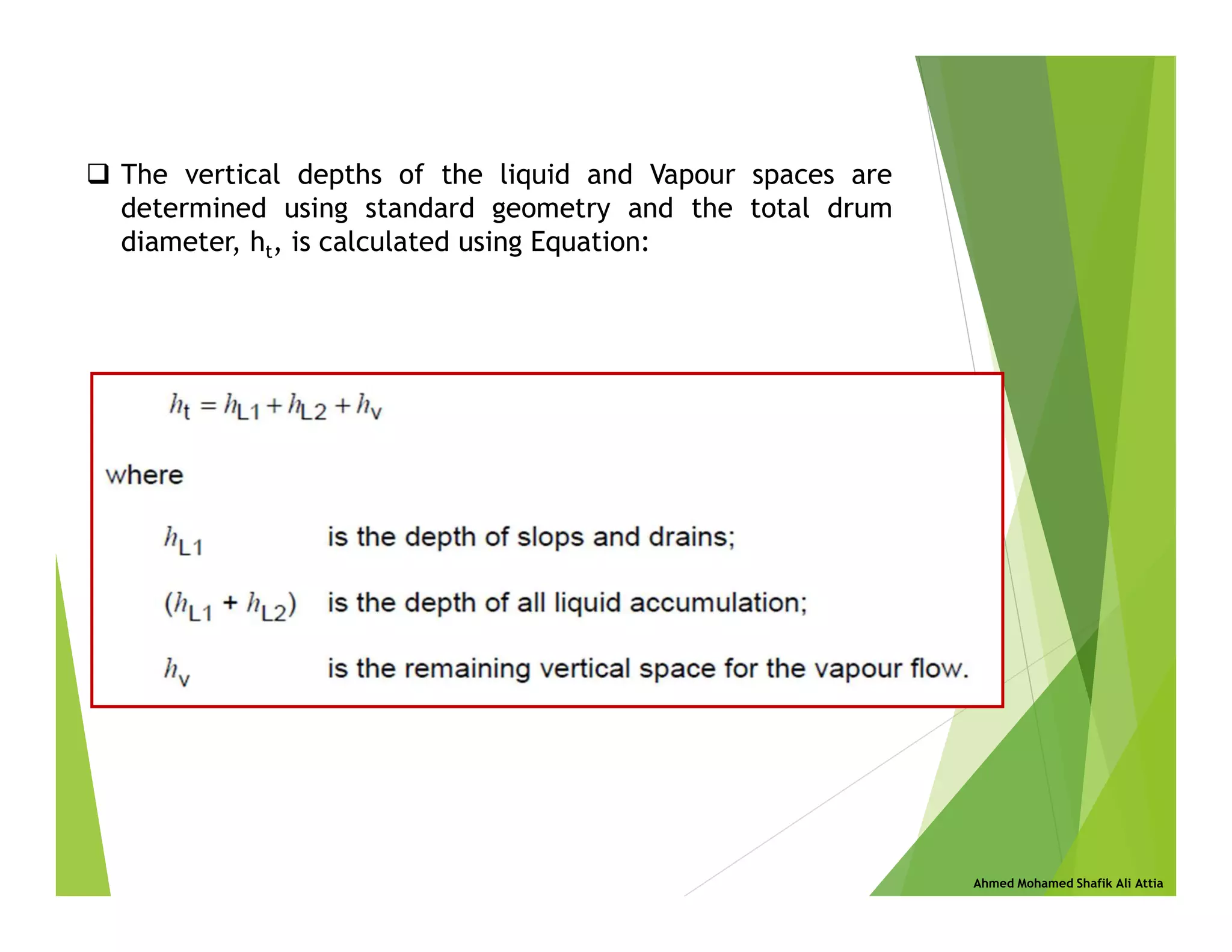
Ht occupied by miscell vol = HL1 + HL2
Area of liq hold up req AL1 + AL2
Radius r m
Vary HL1+2 = HL mm
Balance ht upto centre r - HL m
a angle of one triangle rad
Area of sector m2
Area of triangle m2
Area of liq hold up cal = (sector - triangle area) m2
Vary HL till Area cal = Area req
Find liquid drop out time from Hv & Uc
Vapour space available Hv
Tank diameter - High Liquid Level)
Liquid drop out time Hv/Uc
(Vapour Space Available / Drop out velocity) sec
Vapour velocity
(Vapour flow rate / Vapour Area) m/s
Length req
(Vapour Velcoity*Liquid dropout time) m
End
Assume](https://image.slidesharecdn.com/flaresystemdesign-230317120522-f30aedfd/75/flare-system-design-pdf-46-2048.jpg)

![Ahmed Mohamed Shafik Ali Attia
FLARE LOAD CHECK (within Sterile Area)
Date: 07/20/20
Time: 17:26
By: Ahmed Shafik
Gas Properties:
Mol. Wt Mj 19.9
Flowing Temperature °F Tj (Abs) 130.8
LHV (vol) Btu/scf 1026
LHV (mass) [LHV vol * Mol. Wt] Btu/lb 19,550
Cp/Cv Ratio k 1.247
Compressibility Z 0.9971
Gas Flows:
Flow Rate MMscfd 474.7
Mass Flow lb/h W 1,038,263
Volumetric Flow Acfs 6,474
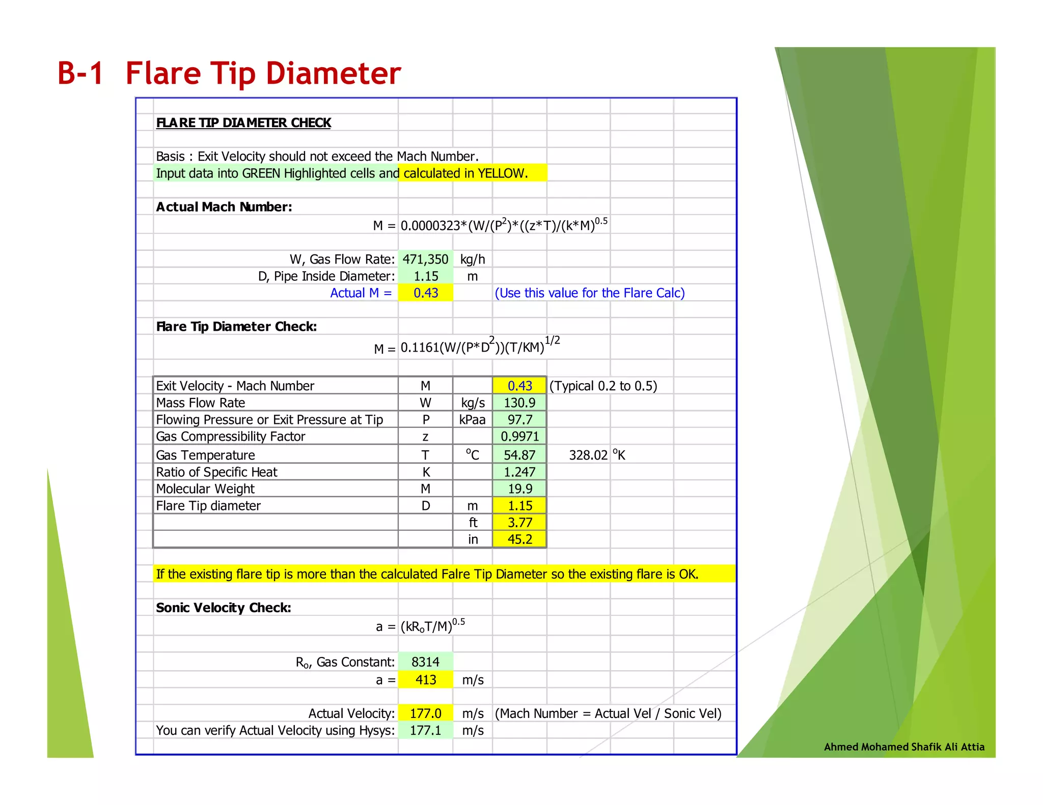
Tip Diameter (Calculated from Flare Tip Sheet) ft dj 3.77
Mach No 0.43
Tip Velocity (Vol flow rate / Area) ft/s Uj 580
Environmental Conds:
Pressure at tip psia Pj 14.17
Relative Humidity %vol g 98
Wind Velocity mph 40
Wind Velocity ft/s Uw 59.1
Solar Radiation Btu/ft²h 381
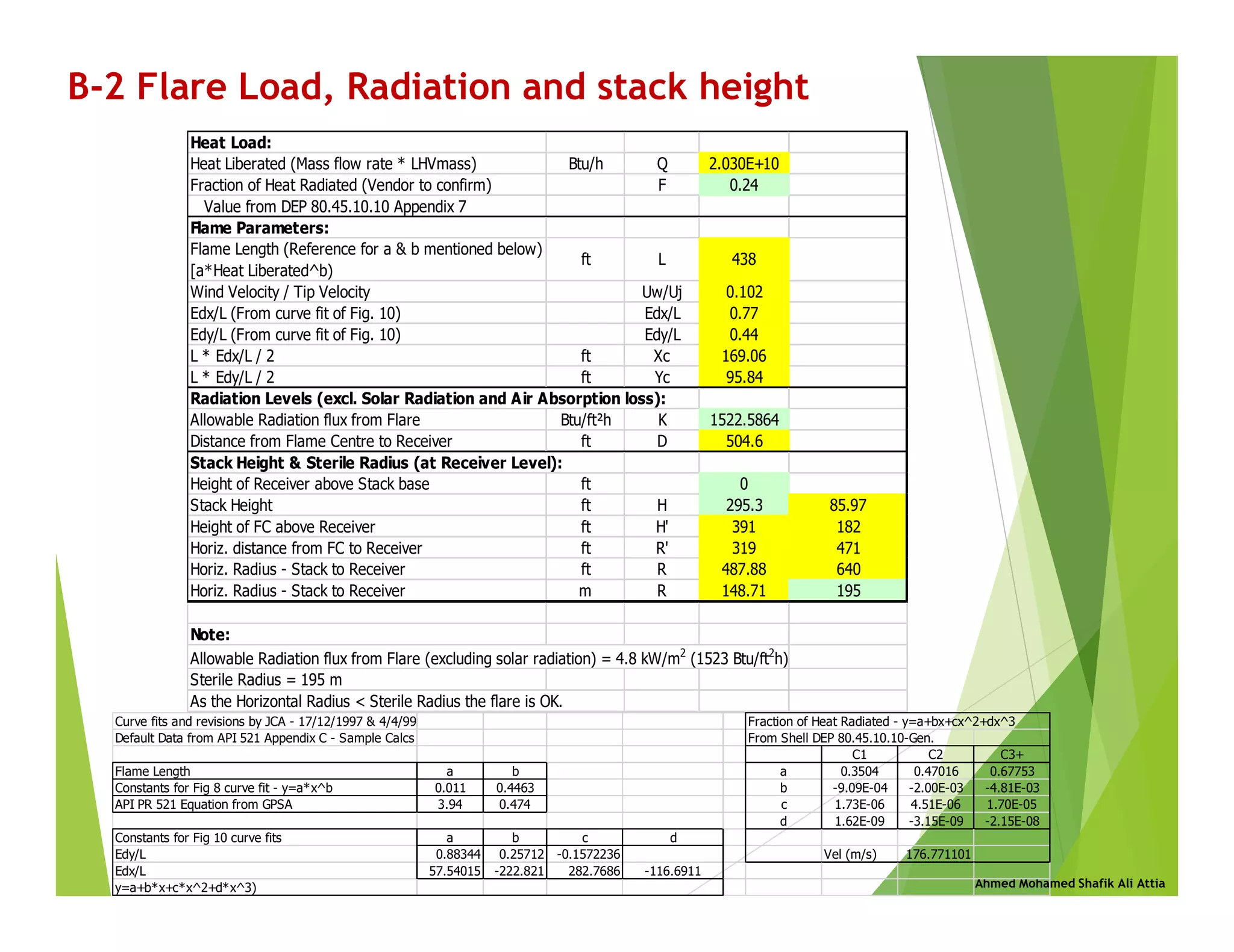
Heat Load:
Heat Liberated (Mass flow rate * LHVmass) Btu/h Q 2.030E+10
Fraction of Heat Radiated (Vendor to confirm) F 0.24
Value from DEP 80.45.10.10 Appendix 7
Flare Calculation to API RP 521 (Simple Approach)
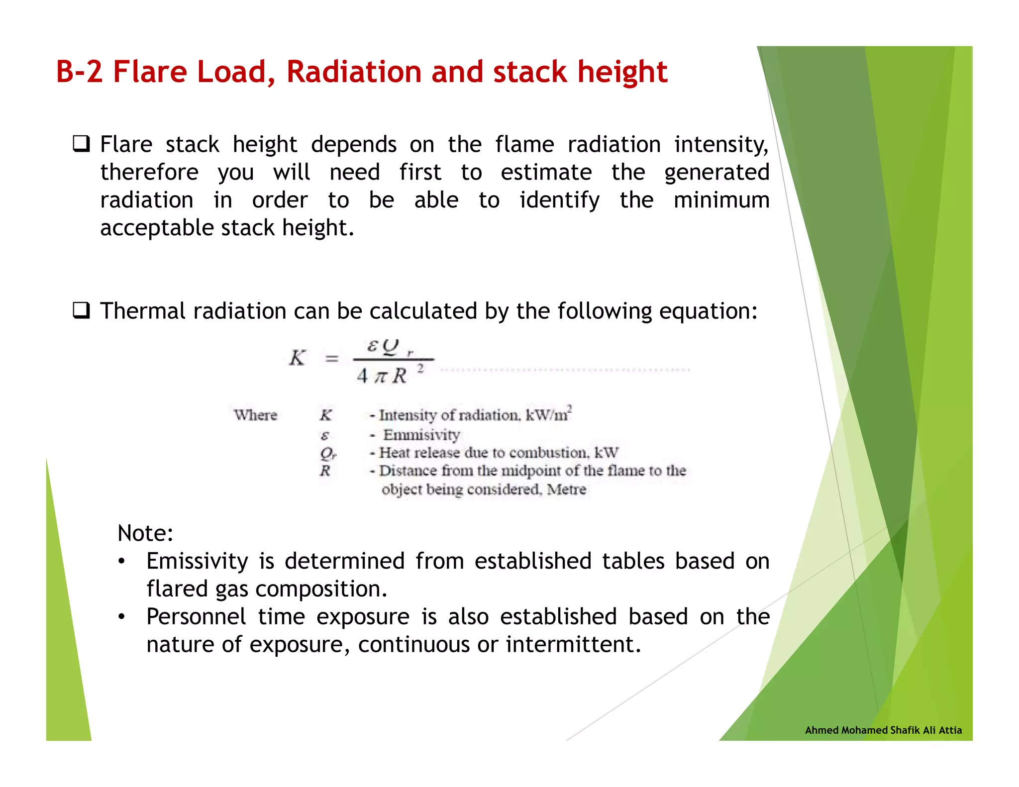
B-2 Flare Load, Radiation and stack height](https://image.slidesharecdn.com/flaresystemdesign-230317120522-f30aedfd/75/flare-system-design-pdf-51-2048.jpg)