This article is about a case study in a 350 MW PF boiler. Flow induced vibration is reported at many plants. Some plant engineers ignore the fact that there are other causes that actually amplify the vibration levels. This article is about the cause that triggered flow induced vibration.
Booking open Available Pune Call Girls Pargaon 6297143586 Call Hot Indian Gi...
Trouble shooting vibration in a pulverised coal fired boiler
1. TROUBLE
BOILER
By K.K.Par
Introductio
Boiler tube
flow induc
the flow i
coincide w
The plant o
plant had
suspected r
in the 2nd
p
4th
units o
different m
different m
used to set
We had vis
performed
reviewed th
also review
during shut
occurred d
due to simp
Data collec
1. The ana
the re
perform
the ana
African
All fou
year. It
tempera
Russian
African
behavio
presente
E SHOOT
rthiban, B.T
on
es may vib
ed vibration
induced vi
with natural
operators o
contacted
resonance o
pass of their
only. The 1
make and the
make. It was
in sometim
sited the pla
combustion
he coal com
wed. This art
t down and
due to comb
ple engineer
ction from
alysis repor
ecent past
mance depar
alysis repo
n coal, Polis
ur coals we
t can be inf
atures are
n coal. At
n coal was
or on sla
ed below.
ING VIBR
Tech ( IIT-M
brate in op
n. This can
ibration of
l frequency
f 1800 MW
us for dia
f economise
r PF boilers
1st
and 2nd
e 5th
and 6th
s learnt tha
mes. The prob
ant and carr
n calculation
mbustion and
ticle is abou
looked for
bustion rel
ring defect.
plant engin
rts of variou
were a
rtment. We
orts of US
sh coal and
ere used in
ferred that
lower in P
the time o
fired. The
agging and
RATION I
M), M.E Th
eration due
n happen w
tube bund
y of the tub
W utility po
agnosis of
er tube bund
s in their 3r
units were
h
units were
at the vibra
blem remai
ried out vib
ns, gas velo
d installatio
ut the diagn
evidence of
ated issue
neers
us coals use
available w
e had review
S coal, So
Russian co
n the previ
the ash fus
Polish coal
of visit, So
e summary
d fouling
IN 2ND
PA
ermal Engin
e to
when
dles
bes.
ower
the
dles
rd
&
e of
e of
ation
ined for nea
bration meas
ocity calcula
on. The past
nosis carried
f vibration.
and
d in
with
wed
outh
oals.
ious
sion
l &
outh
y on
is Figur
Photo
ASS OF A
neering- RE
arly 16 years
surements o
ations and v
t operationa
d out by us.
We conclud
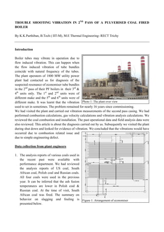
re 1: Arrange
o 1: The plan
PULVERI
ECT Trichy
s since com
of the secon
vibration an
al data and f
Subsequen
ded that the
ement of econ
nt over view
ISED COA
y
mmissioning
nd pass casi
nalysis calcu
field analysi
ntly we visit
e vibrations
nomiser
AL FIRED
.
ing. We had
ulations. We
is data were
ted the plan
would have
D
d
e
e
nt
e
2. 2. Samples of in-house flue gas analysis reports on oxygen and CO for few days were seen in the
DCS. The oxygen percentages from the three on line oxygen analyzers and the portable
instrument were in the range of 3 to 3.5%. The CO values were seen to be less than 18 ppm. This
was excellent. It ruled out vibration possibility due to oxygen starvation / incomplete / delayed
Table 1: Comparison of coal ash characteristics
3. combustion.
3. It was also seen that the units operate on base load. If at all there was any change in combustion
condition, it could only be during the changeover of mills.
4. It was seen that the feeders operate on bias decided by the operators, but it was the mill DP that
was maintained as required. Belt weigh feeders were in use for feeding coal to mills. However
there could be flowability issue in coal chutes during rainy season. At the time of visit, though
there was small drizzle, there was no coal flow problem.
5. It was likely that there could be non-uniform coal distribution between corners, as lot of time
passed after commissioning. It was also likely that CCOFA distribution between corners vary to
some extent. This was based on the observations that the actuator cylinder travel was different
from location to location. However there was no major deviation in CO levels in flue gas.
6. LOI - unburnt carbon in ash- reports were reviewed. The silo ash LOI was reported to be 5-8%.
Since the fixed carbon and FC/VM were high and low NOx burners were in place, the carbon
particle combustion at furnace at coal burner levels would not be complete. Fineness & furnace
residence time would also contribute for the high LOI.
7. We needed to calculate the vibration prediction calculations. The required tube diameter and
pitch details of economiser were collected from the drawings. The data on free unsupported
length of LTSH / Economiser tubes could be read from the pressure part drawings. However
fabrication drawing showing the binding straps / support straps and coil spacer plates were not
available. However in a later visit, we had seen the actual fit up inside and there was no issue on
this.
8. Economiser to air preheater gas ducting drawing was reviewed. The internal stiffener
arrangement details were verified for the economiser ash hoppers and part of the ducts thereafter.
It was seen that hoppers and ducts in the suspected area were designed with internal stiffeners.
The stiffeners do get eroded at the bottom of the duct walls. Annual inspection must address this
area. Some of the gusset plates, internal stiffener members and cross bracing pipes may need
change. Anyhow no defects were seen when the boiler was inspected during a shut down.
Observations during field inspection
Any air ingress can lead to combustion related vibration, due to furnace starvation and secondary
combustion. We looked for possibility of air ingress.
1. It was seen that both units were free of ash in the penthouse top and at hanger penetrations.
However penthouse showed some ash leak marks. Plant engineers who inspected the penthouse
in annual inspection confirmed that there was minor ash accumulations noted at some locations
every year. If there was any ash noticed inside the penthouse, it would be due to missed out seal
welding. It is customary to check for condition of insulation. During the following shut down we
had inspected the penthouse and found to be fairly good. The leaked ash was found fully burnt.
2. There was air ingress around soot blower lance pipe at few locations. However the leaks are not
high enough to cause acoustics. At one plant the vibration of 2nd
pass was set in by the absence of
soot blower lance pipe seal.
3. The air ingress around inspection doors at the 2nd
pass was checked by us. Only minor air ingress
4. was seen at one door. See photo 2 & 3. Using flat sealing rope avoids the leaks.
Photo 2: Air ingress check at soot blower Photo 3: Air ingress check at inspection door
Photo 4: Air ingress at economiser ash conveyor Photo 5: Air ingress at economiser ash conveyor
4. There were 4 ash hoppers at economiser. It was seen that the ash directly falls on a drag chain
conveyor which is ultimately connected to furnace ash conveyor. In unit 4, the ash hopper gates
were partly open. We found air ingress in to the economiser hoppers through the openings of
drag chain conveyor below. See photos 4 & 5 above. Good amount of air ingress in all the 4
pipes could be there, if the gates were full open. But then when the gates were opened full, the
suction effect was not high. There could be ash accumulations in the ash hoppers.
5. In unit 3, no air ingress was seen at drag chain conveyor, as the gates were fully closed.
6. It was not right that the economiser ash hoppers were open to ambient without a proper air lock
device. This was a serious lapse. This would not allow the ash to be evacuated from economiser
ash hopper. Instead fly ash / fused ash particles would be transported to the APH causing
plugging. A plugging of APH would lead to starvation of air for combustion. This can set in to a
combustion induced oscillation. As the APH plugs the flue gas velocity will be high at the free
area causing acoustics. The acoustics can give rise to vibration of the ducts and flooring.
7. It was seen that the buckstay design at top three levels needed to be improved. See photo 6. The
panels were oscillating physically, but the frequency was very less. The vertical buckstay to
horizontal buckstay gap was found to be high. Hence the WW and SCW panels are freely
5. oscillating. The gap should be narrowed down to < 1 mm. Shims can be inserted in the gaps. Or
jack screw can be provided to narrow the gaps. We recommended jack screw to narrow down the
gap.
8. It was seen that the ash conveyor cover plates were cracked. The cracks appeared to be due to
vibration set by acoustics. See photo 7 & 8. Photo 9 shows a duct cracked due to vibration set in
due to high air leakage in another boiler. Once the air ingress was arrested, the vibration was
gone in this case.
Photo 7 & 8: Cracks in the drag chain ash conveyor below economiser hopper.
Photo 6: Buckstay oscillations Figure 2: Jack screw to arrest oscillation
6. 9. It was seen that the 2nd
pass seismic guides were rubbing tight on the structure column. This had
led to transfer of panel oscillations to
floor / hand rail. See photo 10. The gap
needed to be increased to 0.5 to 1 mm.
Guide members are to be cut and
relocated. Here also jack screw could be
given for easy adjustment. We
recommended that present guides must
be cut and shifted during shut down.
Data measurements by us at plant:
1. We had done the gas analysis at APH
inlet at both units. The trend on CO /
Oxygen variation was observed by us. The data measured by us did not show oscillations in
oxygen or CO. We found that there was no possibility of combustion related vibration. However
small pressure fluctuations are noted due to rotary air preheater rotation. This frequency was too
small to cause vibration.
2. We had measured vibration levels at buckstays at all levels. Any vibration of tube bundles should
be ultimately transferred to all connected bodies. Buckstays were the only available cold spots
where a vibration sensor probe could be mounted. During the measurement the units were at full
load. In unit 3, the isolation gates at economiser hoppers were in fully closed condition. In unit 4,
the ash hopper isolation gates were partly open. The ash conveyors were in operation in unit 4.
The vibration measurements were made in I pass too. The spectrum analysis was done
Photo 9: Typical cracks in ducting on account of acoustic vibration at another unit.
Photo 10: Restraints at seismic guide location
7. simultan
was fou
of tubes
was fou
values
reading
Interaction
respect to v
We observ
abnormal v
data in the
discussed th
Their expe
below.
Plant e
when a
hopper,
as of n
such th
in unit
ingress.
and tak
there sh
Inciden
were co
unit 1 &
dropped
the syst
been les
The air
pressure
at econo
Air gus
hopper
mmWC
have be
Plant en
Definite
cause se
After th
confirm
neously. Th
und to be at
s. The displ
und to be 0
were neglig
g can be seen
n with op
vibration
ved there
vibrations
entire 2nd
p
he data with
eriences / o
engineers h
ash was acc
, the vibrat
now there w
here was no
4 hoppers
. The ingres
es to APH.
hould not be
ntally the a
onnected to
& 2. In un
d in to dens
tems cause
ss.
ingress wo
e would be
omiser ash h
shing in lon
above the
C, air ingres
een provided
ngineers inf
ely the ash p
evere plugg
he discussio
m the cause o
he magnitud
a frequency
lacement of
0.1 - 0.2 m
gible. Typic
n in figure 3
perating te
was no
as per the
pass in both
h operating
observation
have expre
cumulated
tion vanish
was no vib
ot much of
, since ther
ss air fluidiz
If there wa
e air ingress
sh from as
lean phase
it 5 & 6 th
se phase sys
negligible a
ould be very
at - 165 mm
hopper.
ng ash drai
ash pipe c
ss could rais
d.
formed that
plugging at
ging.
on with pla
of vibration
de of vibrat
y of 5 - 8.5.
f the boiler
mm. These
cal sample
3.
eam with
acoustic /
measured
h units. We
engineers.
ns were as
essed that
in the ash
hed. Hence
bration. As
ash stored
re was air
zes the ash
as ash, then
s.
sh hoppers
e system in
he ash was
stem. Both
air ingress.
y high if the
mWC (-165
in pipes (37
can cause s
se high velo
t the vibrati
t APH woul
ant engineer
ns.
tion was fo
. This frequ
Hence the a
e gates were
50 Pascal). H
70 mm dia
stereo effec
ocity waves
on would b
ld be high a
rs, it was f
Figure 3: T
ound to be t
uency was n
ash transpor
e fully open
However th
ameter) can
t too. At a
s causing vi
be high whe
at this time.
finalized to
Typical vibra
too small. T
nowhere nea
rtation to R
ned, as the e
here was no
n set up aco
a negative p
ibration. An
en the soot b
Slagging a
carry out
ation spectru
The displac
ar the natura
Rotary APH
economiser
draft tappin
oustics. The
pressure of
n airlock de
blowers we
and fouling
two additio
um report
cement peak
al frequency
would have
r ash hopper
ng available
e pyramida
f minus 165
evice should
re operated
coals would
onal tests to
k
y
e
r
e
al
5
d
d.
d
o
8. The two test conditions
a. Test condition 1: In unit 4, the economiser ash hopper gates were fully opened to check
acoustics by air ingress through drain pipes.
b. Test condition 2: In unit 3, the vibration was measured with soot blower in operation.
Table 2: The above are the vibration levels measured at the four economiser hoppers.
9. The vibration data taken with gate full open at unit 4, did not show any increase in vibration
levels or change in frequency of peak vibration. There was a possibility that ash was
accumulated in the ash hoppers already and the air ingress was much less.
The vibration data taken with soot blowing in unit 3, did not show any increase in vibration
levels or any change in frequency of peak vibration. The frequency of peak was at 8.5 and below.
These were nowhere near the acoustic frequency / vortex frequency / natural frequency of
economiser tubes.
Discussions with operation head of the plant
The subject matter was discussed with operation head of the plant. He stated that the vibration was
seen with some coals. He informed that the vibration would last for two or three days and then
gradually it would subside. The soot blower would not be operated till the vibration subsides. The
gates of economiser ash hoppers would be closed in order to dampen the vibration. Yet the vibration
would not subside immediately. Incidentally Two DCS engineers firmly stated the same behavior of
the boiler at times only. Operational head of the unit requested that the ash hopper shape should be
reviewed. Since the vibration was absent in the US coal / South African coals, the particular
phenomenon would only be related to fouling nature of the coal.
The cause for vibration
The cause became clear. The table 1 revealed that the Polish coal and Russian coal were slagging &
fouling type. The initial deformation temperatures were low in both the coals. The iron loading in
Polish coal was the highest. It was possible that the ash lumps formed due to deposits were carried
forward to rotary air preheater. High level of clogging would lead to many problems. The ash
clogging would be high soon after the soot blowers were operated.
1. Once the top baskets were plugged, the leakage of air to flue gas would increase at the bottom
seals. The flue gas side pressure drop will increase. This would affect the draft conditions in the
furnace. The air flow would have to be reduced. This can set in combustion related pulsations.
2. The high velocity gas flow / air flow in restricted passages in baskets could initiate acoustics. The
declogging of preheater would take a long time. Empty ash hoppers would create more vibration.
Hence accumulating of ash in economiser ash hopper could dampen the vibration.
Interestingly the operation head informed that the previous basket profiles were having more
clogging tendency. He informed that modified basket profile was adopted at present.
Check for gas velocity at ash hopper
The combustion gas volume calculation was made for US coal. The gas volume at one ID fan was
estimated to be 195.57 m3/s. The ID fan provided was of 260 m3/s capacity. The PA fan, FD fan and
ID fan sizing were checked to be OK. It was seen the gas velocity at eco outlet hopper 11.55 m/s at
zone 1 & 16.6 m/s at zone 2. See figure 4. There was no abnormality.
10. Vibration prediction calculations
Flow induced vibration can occur
in a boiler in convective banks.
There are two cases of vibrations
induced by gas flow. They are:
Resonant vibration of a gas
column formed within tube
banks or the ducting or the
enclosure.
Vibration of tubes in tube
banks.
In the first case, a strong acoustic
vibration which can be heard /
felt by personnel in power plant and might induce the vibration of tube banks. In the second case,
tubes are set to oscillatory motion at their natural frequency and this might result in tube failures due
to fatigue.
We can calculate frequencies and check if there is any overlapping of the frequency which can set in
to resonance. The calculations were made and the results are presented in table 4. There was no
possibility of vortex induced vibration in tube banks. The natural frequency of tubes, fn, in this case
were calculated to be 57, 70 and 84. The vortex frequency was found to be well outside the band of
0.8 fn & 1.2 fn. The nearby enclosure could experience the oscillations at the same frequency - but
not with same amplitude. It was measured that frequency of vibration was around 8.5 and below.
The acoustic vibration frequencies of first 3 orders were calculated for the width of casing /
enclosure that was normal to the tube length. The vibration could occur at third mode for the
enclosure. Here the enclosure was the duct / steam cooled wall. The vortex shedding frequency for
lowermost bank could excite the enclosure vibration. The vibration has to occur at 57 Hz. The
measured vibration frequency was only 8.5 which was no way near 57 Hz.
Conclusions
There was no vibration at the time of visit. Hence vortex shedding of tube banks was not the source.
There were three possible mechanisms which could occur at times.
Ash plugging of air heater baskets give raise to acoustic noise which can set the resonance of
casing. As the ash plugs, the gas side velocity will increase immediately. Depending on the
severity of plugging, the gas velocity will increase too high. The cause for this is the ash
chemistry and the fouling. In addition, the separation of ash / evacuation of ash at ash hopper are
Figure 4: Gas velocity at ash hopper
11. affected by the absence of proper air lock device. An airlock device can be a direct connection to
dense phase ash transmitter vessels or a rotary air lock feeder. In the present arrangement, air
lock (rotary pocket feeder) is the simplest solution. Other units had proper sealing arrangements.
See photo 11.
The second mechanism is the air column vibration set in by the air ingress from the four ash
discharge pipes. Here again the solution is providing
an air lock feeder.
The third mechanism is combustion related. As such
the ID fans were running at near full rpm. There was
no margin in the fans to handle to situation of outside
air ingress from the ash discharge pipes or the
additional draft to be handled when the preheater
would be ash-plugged. This calls for measurement of
excessive draft loss / excessive air ingress in the flue
gas duct system. The condition of seals in preheater
decides the air mixing to flue gas. This is known by
measuring the oxygen before and after air preheater.
The air ingress at ESP and at duct expansion bellows
can be known from measuring oxygen at ID fan inlet
or at outlet. Provisions were to be made for the
measurement of drafts and oxygen downstream of
preheater.
Our recommendations for preventing the vibration in II pass of boiler were;
1. Add rotary air lock feeders below the economiser ash hoppers.
2. Ensure the IDT (initial deformation temperature) of the coal ash is above 1400 deg C.
3. Soot blowing shall be staggered to avoid sudden increase of ash loads. Proceed from bottom to
top and return back from top to bottom. This is likely to reduce the sudden ash burden.
4. In case slagging and fouling coals are used, change over to non slagging coals periodically to
remove the deposits in a gradual manner.
We wish the readers are benefitted out of this technical paper.
M/S Venus energy audit system – Trouble shooting of boiler failures
and operational issues. Company carries out design audit, construction
audit, shut down audit and operational audit.
M/S Sri Devi engineering consultancy and agency – engaged in non
pressure parts spares supply for FBC boilers.
M/S Sri Devi boiler equipment and spares – engaged in supply of
pressure part spares for all type of boilers
K.K.Parthiban
Photo 11: Ash removal device in other boiler