API Governance and Monetization - The evolution of API governance
Advanced motion controls 10a8
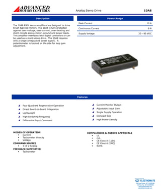
1. Analog Servo Drive 10A8
Description
Power Range
Peak Current 10 A
Continuous Current 6 A
Supply Voltage 20 - 80 VDC
The 10A8 PWM servo amplifiers are designed to drive brush type DC motors. The 10A8 is fully protected against over-voltage, over-current, over-heating and short-circuits across motor, ground and power leads. This amplifier interfaces with digital controllers or can be used as a stand-alone drive. The 10A8 requires only a single unregulated power supply. A potentiometer is located on the side for loop gain adjustment.
Features
Four Quadrant Regenerative Operation
Direct Board-to-Board Integration
Lightweight
High Switching Frequency
Differential Input Command
Current Monitor Output
Adjustable Input Gain
Single Supply Operation
Compact Size
High Power Density
MODES OF OPERATION
ƒ
Current
ƒ
Tachometer Velocity
ƒ
Voltage
COMMAND SOURCE
ƒ
±10 V Analog
FEEDBACK SUPPORTED
ƒ
Tachometer
COMPLIANCES & AGENCY APPROVALS
ƒ
UL
ƒ
cUL
ƒ
CE Class A (LVD)
ƒ
CE Class A (EMC)
ƒ
RoHS
ELECTROMATE
Toll Free Phone (877) SERVO98
Toll Free Fax (877) SERV099
www.electromate.com
sales@electromate.com
Sold & Serviced By:
2. Analog Servo Drive 10A8
BLOCK DIAGRAM
Information on Approvals and Compliances
US and Canadian safety compliance with UL 508c, the industrial standard for power conversion electronics. UL registered under file number E140173. Note that machine components compliant with UL are considered UL registered as opposed to UL listed as would be the case for commercial products.
Compliant with European CE for both the Class A EMC Directive 89/336/EEC on Electromagnetic Compatibility (specifically EN 61000-6-4:2001, EN 61000-6-2:2001, EN 61000-3-2:2000, and EN 61000-3-3:1995/A1:2001) and LVD requirements of directive 73/23/EEC (specifically EN 60204-1), a low voltage directive to protect users from electrical shock.
RoHS (Reduction of Hazardous Substances) is intended to prevent hazardous substances such as lead from being manufactured in electrical and electronic equipment.
ELECTROMATE
Toll Free Phone (877) SERVO98
Toll Free Fax (877) SERV099
www.electromate.com
sales@electromate.com
Sold & Serviced By:
3. Analog Servo Drive 10A8
SPECIFICATIONS
Power Specifications
Description
Units
Value
DC Supply Voltage Range
VDC
20 - 80
DC Bus Over Voltage Limit
VDC
86
Maximum Peak Output Current1
A
10
Maximum Continuous Output Current
A
6
Maximum Power Dissipation at Continuous Current
W
24
Minimum Load Inductance (Line-To-Line)2
μH
200
Switching Frequency
kHz
33
Control Specifications
Description
Units
Value
Command Sources
-
±10 V Analog
Feedback Supported
-
Tachometer
Modes of Operation
-
Current, Tachometer Velocity, Voltage
Motors Supported
-
Single Phase (Brushed, Voice Coil, Inductive Load)
Hardware Protection
-
Over Current, Over Temperature, Over Voltage, Short Circuit (Phase-Phase & Phase-Ground)
Mechanical Specifications
Description
Units
Value
Agency Approvals
-
CE Class A (EMC), CE Class A (LVD), cUL, RoHS, UL
Size (H x W x D)
mm (in)
50.8 x 101.6 x 15.2 (2 x 4 x 0.6)
Weight
g (oz)
145 (5.1)
Heatsink (Base) Temperature Range3
°C (°F)
0 - 65 (32 - 149)
Storage Temperature Range
°C (°F)
-40 - 85 (-40 - 185)
Form Factor
-
PCB Mounted
P1 Connector
-
Two 16-pin, 2.54 mm spaced headers (3 pins removed)
Notes
1.
Maximum duration of peak current is ~2 seconds.
2.
Lower inductance is acceptable for bus voltages well below maximum. Use external inductance to meet requirements.
3.
Additional cooling and/or heatsink may be required to achieve rated performance.
ELECTROMATE
Toll Free Phone (877) SERVO98
Toll Free Fax (877) SERV099
www.electromate.com
sales@electromate.com
Sold & Serviced By:
4. Analog Servo Drive 10A8
PIN FUNCTIONS
P1 - Signal & Power Connector
Pin
Name
Description / Notes
I/O
1
NC
Not Connected (Reserved)
-
2
SIGNAL GND
Signal Ground
GND
3
NC
Not Connected (Reserved)
-
4
+REF IN
Positive Reference Input. ±10 V Operating Range, ±15 V Maximum Input. Referenced To Signal Ground.
I
5
-TACH IN
Negative Tachometer Input (Maximum ±60 V). Use signal ground for positive input.
I
6
+REF IN
Positive Reference Input. ±10 V Operating Range, ±15 V Maximum Input. Referenced To Signal Ground.
I
7
+TACH / GND
Positive Tachometer Input and Signal Ground
GND
8
CURR LIMIT RES
Current Monitor and Current Limit Resistor. This signal is proportional to the actual current output. Scaling is 2 A/V. This pin is also used for current limiting (see P1-9).
O
9
CURR LIMIT RES
Current Limit Resistor. Used to reduce the factory preset maximum current limit. See details below.
I
10
INT CAP
Current Reference and Integrator Capacitor. Measures the command signal to the internal current-loop. This pin has a maximum output of ±7.25 V when the drive outputs maximum peak current. This pin is also used to eliminate velocity/voltage loop integral gain (see P1- 13).
O
11
INV OUT
Output of the internal unity-gain inverting amplifier.
O
12
INHIBIT IN
Apply +3 to +15 V @ 1 mA to inhibit drive. Inhibit turns off all power devices.
I
13
INT CAP
Integrator Capacitor. Shorting this pin to P1-10 eliminates velocity/voltage loop integral gain.
O
14
I
NHIBIT
Apply +15 V or leave open to enable drive. Pull to ground to inhibit drive. Inhibit turns off all power devices.
I
15
VOLT OUT
Output of the internal differential amplifier. This signal is proportional to the output voltage.
O
16
INV IN
Input of the internal unity-gain inverting amplifier.
I
17
GND
GND
18
GND
GND
19
GND
GND
20
GND
Power Ground (Common With Signal Ground)
GND
21
+PWR
I
22
+PWR
I
23
+PWR
DC Power Input
I
24
-MOT
O
25
-MOT
O
26
-MOT
Negative Motor Output
O
27
+MOT
O
28
+MOT
O
29
+MOT
Positive Motor Output
O
Pin Details
CURR LIMIT RES (P1-9)
This pin can be used to reduce the peak and continuous current limits while maintaining their ratio (60%) by connecting an external current limiting resistor between this pin (P1-9) and P1-8. See table below.
Current Limit Resistor
OPEN
20 kΩ
7 kΩ
4 kΩ
1 kΩ
0 kΩ (SHORT)
Peak Current Limit
10 A
8 A
6 A
4 A
2 A
0 A
ELECTROMATE
Toll Free Phone (877) SERVO98
Toll Free Fax (877) SERV099
www.electromate.com
sales@electromate.com
Sold & Serviced By:
5. Analog Servo Drive 10A8
HARDWARE SETTINGS
Mode Selection Table
Mode
CONFIGURATION
CURRENT
Short pin P1-10 to P1-13
VOLTAGE
Short pin P1-15 to P1-5
TACHOMETER VELOCITY
Connect Tachometer to pins P1-5 and P1-7 as described in pin descriptions
Potentiometer Functions
Potentiometer
Description
Turning CW
1
Loop gain adjustment for voltage/velocity modes. Turn this pot fully CCW in current mode.
Increases gain
Note: Potentiometers are approximately linear and have 12 active turns with 1 inactive turn on each end.
MECHANICAL INFORMATION
P1 - Signal & Power Connector
Connector Information
Two 16-pin, 2.54 mm spaced headers (3 pins removed)
Details
Samtec: BCS-116-L-S-PE
Mating Connector
Included with Drive
No INV IN16VOLT OUT15INHIBIT14INT CAP13INV OUT11CURR LIMIT RES9INT CAP10+REF IN6-TACH IN5+TACH / GND7SIGNAL GND2NC3NC1GND17GND18GND19GND20+PWR21+PWR23-MOT24-MOT25+PWR22-MOT26+MOT27+MOT28+MOT29+REF IN4CURR LIMIT RES8INHIBIT IN12
ELECTROMATE
Toll Free Phone (877) SERVO98
Toll Free Fax (877) SERV099
www.electromate.com
sales@electromate.com
Sold & Serviced By:
7. Analog Servo Drive 10A8
PART NUMBERING INFORMATION
APeak Voltage8- Additional OptionsMaximum peak current rating in Amps. Peak voltage rating scaled 1:10 in Volts. Power Supply:DC Power SupplyRevisionAssigned a letter (A through Z) by manufacturer. AC:AC Power SupplyI:Optical IsolationIsolation Option10Command:Analog CommandDD:PWM CommandPeak Current
ADVANCED Motion Controls servo drives are available in many configurations. All models listed in the selection tables of thewebsite are readily available, standard product offerings.
ADVANCED Motion Controls also has the capability to promptly develop and deliver specified products for OEMs with volume requests. Our Applications and Engineering Departments will work closely with your design team through all stages of development in order to provide the best servo drive solution for your system. Equipped with on-site manufacturing for quick- turn customs capabilities, ADVANCED Motion Controls utilizes our years of engineering and manufacturing expertise to decrease your costs and time-to-market while increasing system quality and reliability.
Examples of Customized Products
Integration of Drive into Motor Housing
Integrate OEM Circuitry onto Drive PCB
Mount OEM PCB onto Drive Without Cables
Custom Control Loop Tuned to Motor Characteristics
Multi-axis Configuration for Compact System
Custom I/O Interface for System Compatibility
Custom PCB and Baseplate for Optimized Footprint
Preset Switches and Pots to Reduce User Setup
RTV/Epoxy Components for High Vibration
Optimized Switching Frequency
OEM Specified Connectors for Instant Compatibility
Ramped Velocity Command for Smooth Acceleration
OEM Specified Silkscreen for Custom Appearance
Remove Unused Features to Reduce OEM Cost
Increased Thermal Limits for High Temp. Operation
Application Specific Current and Voltage Limits
Feel free to contact Applications Engineering for further information and details.
Available Accessories
ADVANCED Motion Controls offers a variety of accessories designed to facilitate drive integration into a servo system.
Visit www.a-m-c.com to see which accessories will assist with your application design and implementation. Power Supplies
Shunt Regulators
Filter Cards
Drive(s)
To Motor
All specifications in this document are subject to change without written notice. Actual product may differ from pictures provided in this document.
ELECTROMATE
Toll Free Phone (877) SERVO98
Toll Free Fax (877) SERV099
www.electromate.com
sales@electromate.com
Sold & Serviced By: