Orthographic projection by madhur
•Download as PPT, PDF•
8 likes•5,277 views

This document discusses different types of technical drawing projections used to represent 3D objects in 2D drawings. It describes orthographic projections where projectors are perpendicular to the projection plane, resulting in front, top, and side views of an object. Axonometric projections show an object inclined toward the projection plane in a single view. Multiview projections use front, top, right side, etc. views. First angle and third angle projections determine the placement of views, with first angle being the European standard and third angle being used in America.

Recommended
More Related Content
What's hot
What's hot (20)
Viewers also liked
Viewers also liked (15)
Similar to Orthographic projection by madhur
Similar to Orthographic projection by madhur (20)
More from Madhur Mahajan
Recently uploaded
Recently uploaded (20)
Orthographic projection by madhur
- 2. Projections Projections Parallel/ Cylindrical Perspective/ Conical Oblique Orthographic One-Point Three-PointTwo-Point Cabinet Other Cavalier Multi-view Axonometric First-angle Fourth-angle Third-angle Second-angle Isometric (30°) Di-metric Trimetric
- 5. Oblique Projections • Projectors are parallel to each other but not perpendicular to projection plane • An oblique projection shows front and top surfaces that include the three dimensions of height, width, and depth. • The front or principal surface of an object (the surface toward the plane of projection) is parallel to the plane of projection. • Effective in pictorially representing objects
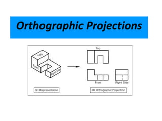
- 6. Orthographic Projections • Orthographic projections are drawings where the projectors, the observer or station point remain parallel to each other and perpendicular to the plane of projection. • Orthographic projections are further subdivided into axonometric projections and multi-view projections. • Effective in technical representation of objects
- 7. Axonometric • The observer is at infinity & the projectors are parallel to each other and perpendicular to the plane of projection. # • A key feature of axonometric projections is that the object is inclined toward the plane of projection showing all three surfaces in one view. • The length of the lines, sizes of the angles, and proportions of the object varies according to the amount of angle between the object and the plane of projection.
- 8. Axonometric The object is tilted with all three coordinate axes are visible in any one view (PP projection plane)
- 9. Orthographic (Orthogonal) The object is at rest and two coordinate axes are visible in any one view (PP projection plane)
- 11. Multiview Projections • Front surfaces of object is parallel to plane of projection • Projectors or line of sights are perpendicular to projection plane • Projectors are parallel to each other and originate from any point on object
- 12. The six views
- 13. Angles • First angle projection – European System • Third angle projection – American System
- 15. First Angle Projection 1 How to draw plan and elevation?
- 16. First Angle Projection 2 How to draw end view?
- 17. First Angle Projection 3 Points to remember: • The ‘front view’ (or elevation) is the view with maximum information. •The ‘plan’ is below the ‘elevation’ (in projection). •The ‘end view’ is placed on the right if viewed from left side of object and on the left if viewed from right side. •‘End view’ and plan face inwards from ‘elevation’.
- 19. Third Angle Projection 1 How to draw plan and elevation? In 3rd angle projection planes are transparent and objects are viewed through them
- 20. Third Angle Projection 2 How to draw end view?
- 21. Third Angle Projection 3 Points to remember: • The ‘front view’ (or elevation) is the view with maximum information. •The ‘plan’ is above the ‘elevation’ (in projection). •The ‘end view’ is placed on the right if viewed from right side of object and on the left if viewed from left side. •‘End view’ and plan face outwards from ‘elevation’.
Editor's Notes
- Front view is Elevation
- For drawing plan and elevation 3D visualisation of objects are essential
- Green arrows and purple arrows show equal distance
- Green arrows and purple arrows show equal distance
- Front view is Elevation
- For drawing plan and elevation 3D visualisation of objects are essential
- Green arrows and purple arrows show equal distance
- Green arrows and purple arrows show equal distance