Downloaded 518 times

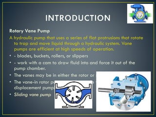
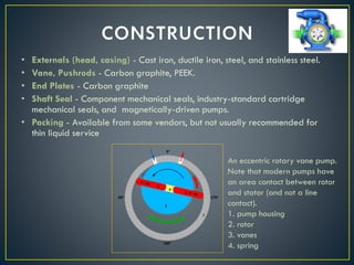
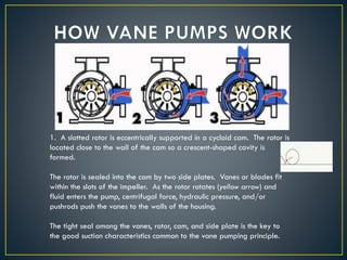
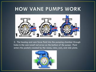
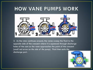
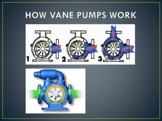

1. A rotary vane pump uses a rotor with slots that hold sliding vanes to trap and move liquid through rotation in a cam housing. 2. As the rotor turns eccentrically in the cam, the vanes slide out to push liquid into pockets then compress it out of discharge ports. 3. Rotary vane pumps are efficient for low viscosity liquids and can handle moderate pressures but wear over time and are not suitable for high viscosity liquids or abrasives.


![[PPT] on Steam Turbine](https://cdn.slidesharecdn.com/ss_thumbnails/spsharmafinalppt-140608082156-phpapp01-thumbnail.jpg?width=640&height=640&fit=bounds)


