1. PULVERISERS5 MIT Pune
1
PROBLEM STATEMENT:
1. To reduce the deflections incurred on the pedal common shaft on the right hand side so as to maintain pedal efficiency during
operation.
2. To reduce the overhang length so as to reduce common shaft’s deflection as well as simplify packaging.
DESIGN CONSTRAINTS:
1. Considering a rear wheel drive (2WD) tractor.
2. The force acting on each pedal is approximated to
600N. (60Kg x 9.81=588.6N) (At any given time during
operation, only one or two such forces can be applied
on any of the pedals on opposite sides, LHS & RHS, as
humans only have two feet).
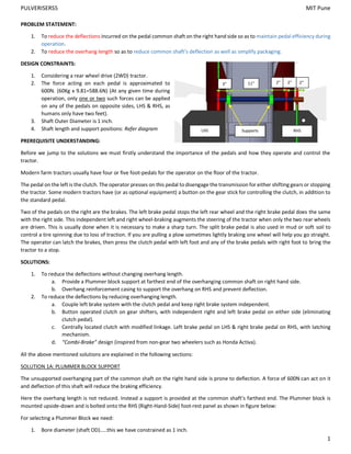
3. Shaft Outer Diameter is 1 inch.
4. Shaft length and support positions: Refer diagram
PREREQUISITE UNDERSTANDING:
Before we jump to the solutions we must firstly understand the importance of the pedals and how they operate and control the
tractor.
Modern farm tractors usually have four or five foot-pedals for the operator on the floor of the tractor.
The pedal on the left is the clutch. The operator presses on this pedal to disengage the transmission for either shifting gears or stopping
the tractor. Some modern tractors have (or as optional equipment) a button on the gear stick for controlling the clutch, in addition to
the standard pedal.
Two of the pedals on the right are the brakes. The left brake pedal stops the left rear wheel and the right brake pedal does the same
with the right side. This independent left and right wheel-braking augments the steering of the tractor when only the two rear wheels
are driven. This is usually done when it is necessary to make a sharp turn. The split brake pedal is also used in mud or soft soil to
control a tire spinning due to loss of traction. If you are pulling a plow sometimes lightly braking one wheel will help you go straight.
The operator can latch the brakes, then press the clutch pedal with left foot and any of the brake pedals with right foot to bring the
tractor to a stop.
SOLUTIONS:
1. To reduce the deflections without changing overhang length.
a. Provide a Plummer block support at farthest end of the overhanging common shaft on right hand side.
b. Overhang reinforcement casing to support the overhang on RHS and prevent deflection.
2. To reduce the deflections by reducing overhanging length.
a. Couple left brake system with the clutch pedal and keep right brake system independent.
b. Button operated clutch on gear shifters, with independent right and left brake pedal on either side (eliminating
clutch pedal).
c. Centrally located clutch with modified linkage. Left brake pedal on LHS & right brake pedal on RHS, with latching
mechanism.
d. “Combi-Brake” design (inspired from non-gear two wheelers such as Honda Activa).
All the above mentioned solutions are explained in the following sections:
SOLUTION 1A: PLUMMER BLOCK SUPPORT
The unsupported overhanging part of the common shaft on the right hand side is prone to deflection. A force of 600N can act on it
and deflection of this shaft will reduce the braking efficiency.
Here the overhang length is not reduced. Instead a support is provided at the common shaft’s farthest end. The Plummer block is
mounted upside-down and is bolted onto the RHS (Right-Hand-Side) foot-rest panel as shown in figure below:
For selecting a Plummer Block we need:
1. Bore diameter (shaft OD)…..this we have constrained as 1 inch.
3” 11” 2” 2”2”
LHS RHSSupports
2. PULVERISERS5 MIT Pune
2
2. Dynamic load Capacity, so as to select a bearing capable of handling such a load (600N).
Using formula:
C = P (L10)p
Where, C= Dynamic load capacity (N)
P=Load (600N x 1.5 load application factor = 900N)
L10= Bearing Life (100 Million Revolutions)
P= 0.3 (roller bearing)
C=900(100)0.3
C=3582.96N
Using SKF OEMs we select:
OEM SKF DESIGNATION NUMBER
Plummer block housing SNL 506-605 (da=25.4mm)
Bearing 22206 K
SOLUTION 1B: OVERHANG REINFORCEMENT CASING
Considering the overhanging shaft to be of length 6 inch on RHS. The left brake pedal is placed at 2 inch from support and the right
brake pedal is placed at 4 inch from the support. When the driver presses the left brake pedal with a force of 60Kg, assuming the
length of pedal to be 12 inches , a torque of 600*304.8=182.88KNmm acts on the shaft .
Using Formula:
Y = (M/2EI) * (L2
-2Lx + x2
)
Where, y= deflection (mm)
M= couple (182.88KNmm)
E= modulus of Elasticity (210GPa)
I = moment of inertia of shaft (pi/64)*d4
(mm4
)
L= overhang length (6 inch = 152.4mm)
x = distance of force acting on shaft from unsupported end of shaft (4inch = 101.6mm)
Therefore the deflection on shaft when LH pedal is pressed is 0.0549mm.
Now when right brake pedal is pressed, same torque will be acting on the shaft but will act at a distance of 4 inch from the support.
Therefore by similar calculation the deflection of shaft when right brake pedal is pressed is calculated as 0.219mm.
When a Plummer block or reinforcement casing provides a support at the end of the overhanging shaft, the shaft is supported at both
the ends. Therefore when the left brake pedal is pressed torque will be acting at 2 inch from left supported end and deflection of shaft
is calculated similarly as 0.0018mm. Thus using Plummer block reduces the deflection from 0.0549mm to 0.0018 mm.
SOLUTION 2A: COUPLE LEFT BRAKE SYSTEM WITH THE CLUTCH PEDAL AND KEEP RIGHT BRAKE SYSTEM INDEPENDENT
In this solution the clutch pedal also operates as the left brake pedal. (This is done by attaching the LHS braking link to the clutch
pedal). As a result we have one less pedal to incorporate on the RHS. Hence the overhanging common shaft’s length is reduced and
hence the deflection is also reduced.
Plummer Block
Shaft
Shaft
Overhang
Reinforcement casing
3. PULVERISERS5 MIT Pune
3
This design offers independent braking only to the Right Rear
wheel. Hence the tractor can make tight right hand turns
when only the right brake pedal is pressed. In case the clutch
is pressed the tractor will stop as the transmission will get
disengaged and further the left brake also gets actuated.
Disadvantage:
The incapability of the tractor to make sharp left hand turns
is the only short coming of the design.
Advantage:
Apart from the shortened common shaft, another advantage would be reduced cost as one less pedal has to be made.
SOLUTION 2B: BUTTON OPERATED CLUTCH ON GEAR SHIFTERS, WITH INDEPENDENT RIGHT AND LEFT BRAKE PEDAL ON EITHER SIDE
(ELIMINATING CLUTCH PEDAL)
In many modern day tractors electronic controls are replacing conventional mechanisms. This
solution is inspired from John Deere PTO control. Here clutching can be done by electrical and
hydraulic means, rather than the conventional links & mechanisms. As a result we can eliminate
the clutch pedal. We can place the left brake pedal on LHS and Right Brake Pedal on RHS. Thus
the overhang length of common shaft gets reduced. Since both the brakes are independent the
tractor can take tight turns on both LHS and RHS.
Disadvantages:
System is more expensive.
In case of electrical failure the tractor will be stuck as there is no way to put it into gear, (it can be stopped by pressing brakes and
stalling). It might involve slight redesign/modification of clutch system.
Advantage:
Reduced overhang of common shaft.
One less pedal as clutch pedal is eliminated.
SOLUTION 2C: CENTRALLY LOCATED CLUTCH WITH MODIFIED LINKAGE. LEFT BRAKE PEDAL ON LHS & RIGHT BRAKE PEDAL ON RHS,
WITH LATCHING MECHANISM
This solution is an alternative which builds on the short comings of solution 2b.
Here the clutch pedal is centrally mounted (i.e. between LHS and RHS), and it is connected to the clutch system by a modified linkage.
Only the brake pedals are attached on the common shaft;
Left brake pedal on LHS and Right brake pedal on RHS).
Hence common shaft length is reduced. Both brake
pedals are independent of each other.
NEED FOR A LATCHING MECHANISM:
Since there are now three pedals and humans only have
two feet trying to stop the vehicle would become very
difficult or instead one brake may not get used.
To stop the vehicle one foot will have to operate the
clutch pedal. Thus now the driver can only press one of
the brake pedals with his/her other foot.
LHS brake connecting link
Clutch connecting link
LHS brake
pedal
Pin
Centrally
located clutch
pedal
John Deere PTO
4. PULVERISERS5 MIT Pune
4
A solution for this would be a Latching Mechanism. The right brake pedal is keyed to the common shaft and rotates with the common
shaft. The left brake pedal is only pivoted on the common shaft with the help of a bush, and its rotation is independent of that of the
common shaft.
As seen from the figure there is a latching bracket keyed to the shaft on the LHS when the left brake pedal is latched to this bracket.
The brake pedal is no longer independent of the common shaft and will now rotate with the common shaft. Hence as the right brake
pedal gets pressed both the brakes (LHS & RHS) get actuated.
The Latching pin is simply a threaded screw which can turned clockwise to latch or counter clockwise to unlatch. This cannot be done
during operation.
As a fail-safe if the system is unlatched and the user wants to stop the tractor another technique is to first clutch and shift into neutral
and then leave the clutch pedal and press both brakes.
Disadvantage:
Latching cannot be done during operation.
Pedal mounting will take some getting used to or may not favor all users as normally we use clutch pedal on the left of our brake
pedals, not between the brake pedals.
Advantage:
Both brakes are independent so taking tight turns is possible on both LHS and RHS.
Since there are only two pedals on the common shaft, overhang length gets reduced.
SOLUTION 2D: “COMBI-BRAKE” DESIGN
This solution is inspired from non-geared two wheelers such as the Honda Activa.
On the LHS we have a clutch pedal pivoted on the common shaft (using a bush) as well as a threaded pin screwed into the common
shaft (perpendicular to the shaft surface in plane with the right brake pedal). On the RHS we have the right brake pedal keyed to the
common shaft. Thus as the brake pedal rotates, the common shaft also rotates, and the pin on LHS rotates in the same direction as
the right brake pedal.
As seen in the figure, the right brake connecting link is connected to the right brake pedal and the left brake connecting link is
connected to the pin on the LHS.
Thus as the user presses the right brake pedal both LHS and RHS brakes get actuated. The left foot only operates the clutch.
Disadvantage:
A major drawback of this design is that the brakes are not independent and so taking tight turns on either side is not possible.
Advantage:
Simple to design
& maintain.
Simple to operate.
One pedal is
reduced so cost
goes down
slightly.
Common shaft
overhang length is
reduced.
Common Shaft
Brake Pedal
keyed to shaft
Clutch Pedal
LHS Brake
connecting
Link attached
to shaft
RHS Brake
connecting
Link attached
to Brake Pedal