NCIT civil (NVQ 5, Sri Lanka) field reports
•
0 likes•299 views

Field reports Biyagama water treatment plant

Recommended
More Related Content
What's hot
What's hot (20)
Similar to NCIT civil (NVQ 5, Sri Lanka) field reports
Similar to NCIT civil (NVQ 5, Sri Lanka) field reports (20)
More from LAKSHITHA RAJAPAKSHA
More from LAKSHITHA RAJAPAKSHA (20)
Recently uploaded
Recently uploaded (20)
NCIT civil (NVQ 5, Sri Lanka) field reports
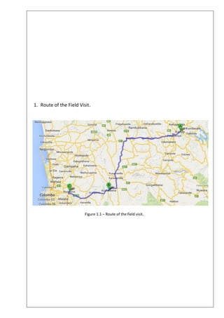
- 1. 1. Route of the Field Visit. Figure 1.1 – Route of the field visit.
- 3. 3. Water Purification. Figure 3.1 – Process of water purification Water is a basic necessity for all life forms to survive. Water is a precious commodity and is also scarce one. It is a valuable commodity, which requires careful management of the water resources and water treatment processes. The water treatment processes should also suit the raw water quality. With increasing pollution of the waterways and water catchment areas the widely used coagulation, flocculation and sand filtration technology may no longer work effectively. As such in time to come the use of advanced water treatment technology such as membranes may have to be used to remove the natural organic matters in the water. With these membrane technology even seawater could be recovered for drinking and potable use.
- 4. 4. Biyagama Water Treatment Plant. 4.1. Description. Figure 4.1 – An aerial view of the Water Treatment Plant Biyagama water treatment plant is a ISO certified water treatment plant for processing and supplying of drinking water. It is constructed sccording to the concept of Mahinda Chinthana vision for future to provide safe drinking water for all. The project was funded by the government of Denmark and The government of Sri Lanka. National Water Supply and Drainage Board is governing the treatment plant. 4.2. Project Data. o Production : 180,000 o Population Coverage : 1,000,000 o Water supply areas : Biyagama Divisional Secretariat Kelaniya Divisional Secretariat Mahara Divisional Secretariat Wattala Divisional Secretariat Ja-Ela Divisional Secretariat Dompe Divisional Secretariat o Salinity Barrier stage 1 : To prevent the raw water from salinity instrusion. o Project Cost : Rs. 10,150 million. o Funded By : Government of Denmark and Government of Sri Lanka o Controlling : National Water Supply and Drainage Board
- 5. 4.3. Plant Description. Intake Structure (Stage 1 & 2) 2 Raw Water Regulation tank 1 Mixing Chamber 1 Flocculator / Clarifier 6 Filter 8 Clear Water / Contact Tank 1 4.4. Plant Details. 4.4.1. Raw Water Intake Plant. Extract raw water from Kelani river. Removing course and fine (up to 5mm) particles contains in raw water via coarse and fine screens. Pumping raw water to mixing chamber at treatment plant. 4.4.2. Mixing Chamber Figure 4.4.2.1 – Mixing Chamber Receiving of raw water from the intake plant. Chemicals are added to start the coagulation. Pre Chlorine is added at upstr eam via submerged distributor . Pre lime is added at 1st compartment using top lime distributor for support the coagulation by pH correction. Alum is added at2nd compartment using top alum distributor for coagulation.
- 6. 4.4.3. Flocculators Tank & Lamella Clarifiers. The purpose of this process is to remove 80% - 85% of suspended solids contains in the raw water. Flocculation Tanks Double stage Flocculation. 2 flocculators in each stage. Flocculation retention time : 27 minutes Flocculator type : propeller type Driver : 1st & 2nd stage flocculator with variable speed drive. Lamella Clarifiers Sludge settled from clarification process is collected to the hoppers. Dislodging is achieved hydraulically by pipes installed at the sludge hoppers Each clarifier tank is having its own impendent sludge draw off control system. Dislodging is automatic by actuated valves opened on time. 4.4.4. Sand Filters Figure 4.4.4.1 – Sand Filters The purpose of sand filters are to remove the fine particle in settled water which cannot be removed at the clarifier. 8nos. of double – bed rapid gravity sand filter. Constant flow, constant head type. False bottom under drain system
- 7. Filteration rate All in servise : 8.3 / One out of service : 9.5 / Filter media : Sand & Gravel Sand effective size : 0.9 - 1.0 mm Uniform coefficient of sand : 1.7 Gravel effective size : 4.0 – 8.0 mm Deptha of sand layer : 900 mm Depth of gravel layer : 100 mm Filter Oparation. Designed filter run time : 48 Hours Control of filter operation : 3 modes Automatic : Filter backwashing is performed automatically. Semi Auto : Filter backwashing is manually initiated. However, the backwash sequence is automatic. Manual : Filter backwashing is performed by manual. Opening and closing of valves / penstocks via the filter console. Filter Backwashing Filter backwashing is initiated due to achieving of 48 hrs operation or choke, whichever comes first Only one filter can be backwashed at a time. Backwashing steps; Lower the water level up to weir level. Air source only (3 minutes) Combined wash (5 minutes) Rising & surface sweeping (5minutes)
- 8. 4.4.5. Contact / Clear water tanks Contact tank The purpose of contact tank is to enhance the disinfection process. One RC baffled contact tank with 2 compartments. The post chlorine is dosed at contact tank inlet. Post lime saturator installed on top of the contact tank, saturated lime is dosed at outlet weir for pH adjustment. Clear Water Tank The purpose of clear water tank is to store the treated water. One clear water tank with 2 compartments. Total capacity of the tank 7000 4.4.6. Treated Water Pumps Pump set Flow & Head Operation 2 set wash water pump (2 duties/ 1 standby) 262 @ 12m Fixed speed 4 set Church Hill pump (3duties/ 1standby) 702 @ 72.95m Fixed speed 2 set Ambatale pump (1 duty/ 1 standby) 5.261 @ 8.74m Fixed speed 4.4.7. Chemical Plant The purpose of chemical plant is to prepare and dose the chemicals. All chemical (Alum, Lime & Polymer) except chlorine are supplied in bags. Chemical bags are handled by semi electric stacker. Chlorine delivered in drums and handled by an over head crane. 4.4.8. Sludge Treatment Plant The purpose of sludge treatment plant is to receive the residues of water treatment, recower the settled water and remove the sludge in solid form. 2 nos. of wash water recovery tanks 1 nos. of sludge balancing tank 1 nos. of sludge thickener tank 1 nos. of thickener sludge tank
- 9. 5. References. Biyagama Water treatment plant leaflet. National Water Supply and Drainage Board website. www.waterboard.lk Penang Skills Development Centre web site. www.psdc.org