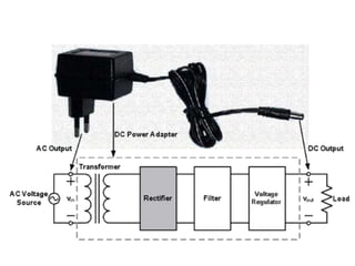
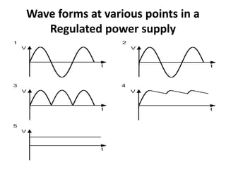
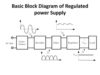
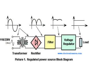
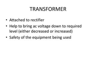
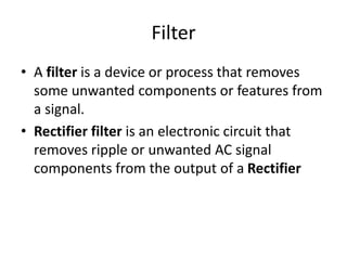
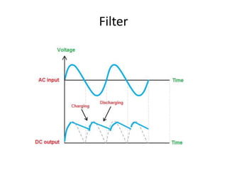
Power Supply
Power Supply
• An electrical device that supplies electrical
power to electrical load
• Function:
– Convert electrical current from a source to the
correct voltage, current and frequency to power
the load
Current
• The rate of flow of electric charge
• Types of Current
– AC (alternating current)
– DC (direct current)
Alternating Current
• Electric current that periodically reverses
direction
• Produce by “alternator”
• Current (when modify)
• Typically use in power supplies
Alternating Current
• Waveform
Sine Wave
Parts of a Sine Wave
• Amplitude, frequency and phase
Direct Current
• Electric current flows in one direction
• Batteries
• Produce by “Commutator”
• Voltage when modify
Direct Current
• Waveform
Rectifiers, Filters and Regulator
Marks 16
Visit for more Learning Resources
Wave forms at various points in a
Regulated power supply
Basic Block Diagram of Regulated
power Supply
TRANSFORMER
• Attached to rectifier
• Help to bring ac voltage down to required
level (either decreased or increased)
• Safety of the equipment being used
Rectifiers
• Rectifier is an electronic device which is used
for converting an alternating quantity (Voltage
or current) into unidirectional i.e. DC quantity
(Voltage or current).
Rectification
• Rectification is a process of converting the
alternating quantity (voltage or current) into a
corresponding direct quantity(voltage or
current).
• The input to a rectifier is AC whereas its
output is unidirectional or DC.
Need of Rectification
• Every electronic circuit such as amplifiers,
needs a DC power source for its operation.
• This DC voltage has to be obtained from AC
supply.
• For this the AC supply has to be reduced ()
Stepped down first using a Step down
transformer and then converted to dc by using
rectifier.
Types of Rectifier
Half Wave Rectifier
Full Wave Rectifier (Center Tapped
Transformer)
Filter
• A filter is a device or process that removes
some unwanted components or features from
a signal.
• Rectifier filter is an electronic circuit that
removes ripple or unwanted AC signal
components from the output of a Rectifier
Filter
Filter
Frequency Signal Output
0 Hz to 0.5Hz
Great amount of attenuation;
Almost Completely Blocked
0.5Hz to 3Hz
Some attenuation of the signal but
not much
3Hz and Above
Signal goes through completely
unimpeded; No attenuation
Voltage Regulator
• A voltage regulator is a system designed to
automatically maintain a constant voltage
level.
• A voltage regulator may use a simple feed-
forward design or may include negative
feedback. It may use an electromechanical
mechanism, or electronic components

Rectifiers-Filters-and-Regulator-1.pptx

  • 1.
  • 2.
    Power Supply • Anelectrical device that supplies electrical power to electrical load • Function: – Convert electrical current from a source to the correct voltage, current and frequency to power the load
  • 3.
    Current • The rateof flow of electric charge • Types of Current – AC (alternating current) – DC (direct current)
  • 4.
    Alternating Current • Electriccurrent that periodically reverses direction • Produce by “alternator” • Current (when modify) • Typically use in power supplies
  • 5.
  • 6.
  • 7.
    Parts of aSine Wave • Amplitude, frequency and phase
  • 8.
    Direct Current • Electriccurrent flows in one direction • Batteries • Produce by “Commutator” • Voltage when modify
  • 9.
  • 10.
    Rectifiers, Filters andRegulator Marks 16 Visit for more Learning Resources
  • 12.
    Wave forms atvarious points in a Regulated power supply
  • 13.
    Basic Block Diagramof Regulated power Supply
  • 15.
    TRANSFORMER • Attached torectifier • Help to bring ac voltage down to required level (either decreased or increased) • Safety of the equipment being used
  • 16.
    Rectifiers • Rectifier isan electronic device which is used for converting an alternating quantity (Voltage or current) into unidirectional i.e. DC quantity (Voltage or current).
  • 17.
    Rectification • Rectification isa process of converting the alternating quantity (voltage or current) into a corresponding direct quantity(voltage or current). • The input to a rectifier is AC whereas its output is unidirectional or DC.
  • 18.
    Need of Rectification •Every electronic circuit such as amplifiers, needs a DC power source for its operation. • This DC voltage has to be obtained from AC supply. • For this the AC supply has to be reduced () Stepped down first using a Step down transformer and then converted to dc by using rectifier.
  • 19.
  • 20.
  • 21.
    Full Wave Rectifier(Center Tapped Transformer)
  • 23.
    Filter • A filteris a device or process that removes some unwanted components or features from a signal. • Rectifier filter is an electronic circuit that removes ripple or unwanted AC signal components from the output of a Rectifier
  • 24.
  • 25.
    Filter Frequency Signal Output 0Hz to 0.5Hz Great amount of attenuation; Almost Completely Blocked 0.5Hz to 3Hz Some attenuation of the signal but not much 3Hz and Above Signal goes through completely unimpeded; No attenuation
  • 26.
    Voltage Regulator • Avoltage regulator is a system designed to automatically maintain a constant voltage level. • A voltage regulator may use a simple feed- forward design or may include negative feedback. It may use an electromechanical mechanism, or electronic components

Editor's Notes

  • #6 Periodicall varying voltage, current,or electromagnetic field
  • #7 Or sinusoid , a mathematical curve that describes a smooth periodic oscillation Continuous wave Sine function
  • #8 V(t) – voltage as function of time (voltage changes as time changes) Vp – amplitude, describe the maximum voltage that sine wave can reach (either direction) Vp+, Vp- Sin() function – indicates that the voltage is a periodic sine wave (oscillation) 2Π – constant convert frequency from cycle (Hz) to angular frequency (radian/recond) unit for rotational speed f – frequency of sine waven Hz or per unit time t – independent variable, as time varies wave form varies Φ – phase – how waveform shifted w/ respect of time
  • #16 Transformer is a device which reduces or increases the AC voltage. The step-down transformer reduces the AC voltage from high to low whereas the step-up transformer increases the AC voltage from low to high
  • #21 HWR. The half wave rectifier only passes the one half of the input sine wave (either positive or negative) and rejects the other half. The output of the half wave rectifier is pulsating DC. PN junction DIODE -The most common function of a diode is to allow an electric current to pass in one direction while blocking it in the opposite direction (the reverse direction) LIKE A VALVE In half wave rectifier, we generally use a step-down transformer because the voltage needed for the diode is very small applying a large AC voltage without using transformer will permanently destroy the diode.
  • #22 A full wave rectifier is a type of rectifier which converts both half cycles of the AC signal into pulsating DC signal.
  • #24 A filter capacitor is a capacitor which filters out a certain frequency or range of frequencies from a circuit. Usually capacitors filter out very low frequency signals. These are signals that are very close to 0Hz in frequency value. These are also referred to as DC signals. Removes undesirable frequencies
  • #26 reduction in the strength of a signal.