Simulation of Induction Furnace Comparison with Practical Induction Furnace
•
2 likes•768 views

In this paper, at first, a simulation of induction furnace model optimized resonant capacitor is designed for a practical induction furnace with parallel resonant inverter. Then rectifier and inverter snubber circuit are designed. And taken voltage, current, THD and power measured. This measured value comparison with actual working industry furnace data. and conclude that when furnace is not operate at full load that time its power factor is very low. And THD is high.

Recommended
Recommended
More Related Content
What's hot
What's hot (20)
Similar to Simulation of Induction Furnace Comparison with Practical Induction Furnace
Similar to Simulation of Induction Furnace Comparison with Practical Induction Furnace (20)
More from ijsrd.com
More from ijsrd.com (20)
Recently uploaded
Recently uploaded (20)
Simulation of Induction Furnace Comparison with Practical Induction Furnace
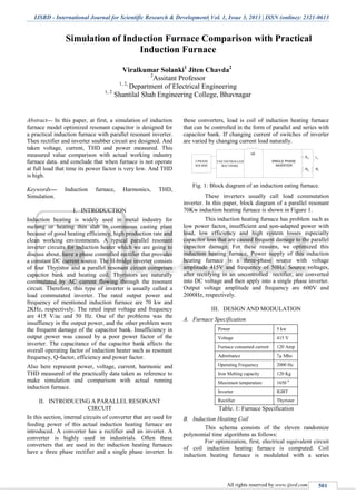
- 1. IJSRD - International Journal for Scientific Research & Development| Vol. 1, Issue 3, 2013 | ISSN (online): 2321-0613 All rights reserved by www.ijsrd.com 501 Simulation of Induction Furnace Comparison with Practical Induction Furnace Viralkumar Solanki1 Jiten Chavda2 2 Assitant Professor 1, 2, Department of Electrical Engineering 1, 2 Shantilal Shah Engineering College, Bhavnagar Abstract— In this paper, at first, a simulation of induction furnace model optimized resonant capacitor is designed for a practical induction furnace with parallel resonant inverter. Then rectifier and inverter snubber circuit are designed. And taken voltage, current, THD and power measured. This measured value comparison with actual working industry furnace data. and conclude that when furnace is not operate at full load that time its power factor is very low. And THD is high. Keywords— Induction furnace, Harmonics, THD, Simulation. I. INTRODUCTION Induction heating is widely used in metal industry for melting or heating thin slab in continuous casting plant because of good heating efficiency, high production rate and clean working environments. A typical parallel resonant inverter circuits for induction heater which we are going to discuss about, have a phase controlled rectifier that provides a constant DC current source. The H-bridge inverter consists of four Thyristor and a parallel resonant circuit comprises capacitor bank and heating coil. Thyristors are naturally commutated by AC current flowing through the resonant circuit. Therefore, this type of inverter is usually called a load commutated inverter. The rated output power and frequency of mentioned induction furnace are 70 kw and 2KHz, respectively. The rated input voltage and frequency are 415 V/ac and 50 Hz. One of the problems was the insuffiency in the output power, and the other problem were the frequent damage of the capacitor bank. Insufficiency in output power was caused by a poor power factor of the inverter. The capacitance of the capacitor bank affects the overall operating factor of induction heater such as resonant frequency, Q-factor, efficiency and power factor. Also here represent power, voltage, current, harmonic and THD measured of the practically data taken as reference to make simulation and comparison with actual running induction furnace. II. INTRODUCING A PARALLEL RESONANT CIRCUIT In this section, internal circuits of converter that are used for feeding power of this actual induction heating furnace are introduced. A converter has a rectifier and an inverter. A converter is highly used in industrials. Often these converters that are used in the induction heating furnaces have a three phase rectifier and a single phase inverter. In these converters, load is coil of induction heating furnace that can be controlled in the form of parallel and series with capacitor bank. If changing current of switches of inverter are varied by changing current load naturally. LI RI 3-PHASE SOURSE UNCONTROLLED RECTIFIRE SINGLE PHASE INVERTER LC XC RC Fig. 1: Block diagram of an induction eating furnace. These inverters usually call load commutation inverter. In this paper, block diagram of a parallel resonant 70Kw induction heating furnace is shown in Figure 1. This induction heating furnace has problem such as low power factor, insufficient and non-adapted power with load, low efficiency and high system losses especially capacitor loss that are caused frequent damage to the parallel capacitor damage. For these reasons, we optimized this induction heating furnace, Power supply of this induction heating furnace is a three-phase source with voltage amplitude 415V and frequency of 50Hz. Source voltages, after rectifying in an uncontrolled rectifier, are converted into DC voltage and then apply into a single phase inverter. Output voltage amplitude and frequency are 600V and 2000Hz, respectively. III. DESIGN AND MODULATION Furnace SpecificationA. Power 5 kw Voltage 415 V Furnace consumed current 120 Amp Admittance 7µ Mho Operating Frequency 2000 Hz Iron Melting capacity 120 Kg Maximum temperature 1650 0 Inverter IGBT Rectifier Thyrister Table. 1: Furnace Specification Induction Heating CoilB. This schema consists of the eleven randomize polynomial time algorithms as follows: For optimization, first, electrical equivalent circuit of coil induction heating furnace is computed. Coil induction heating furnace is modulated with a series
- 2. Classification of Malware based on Data Mining Approach (IJSRD/Vol. 1/Issue 3/2013/0024) All rights reserved by www.ijsrd.com 502 connection of a resistor and an inductor. For the simulation of induction furnace, electrical RC and RL load taken from Matlab library. Power loss in the capacitor bank is the resistor of capacitor model. So, electrical model for parallel resonance induction heating coil and capacitor bank illustrated in Fig 2. X C RC Zt LI RI Fig. 2 : Electrical Equivalent circuit for induction heating furnace coil. IV. SUGGESTED CONTROL METHOD Output power on the coil of this induction heating furnace is not constant. This affair is caused introduced problems in the Section II. For improving feeding system of furnace, we suggest uncontrolled tree phase rectifier convert into controlled three-phase rectifier and design a passive controller for system that by changing the rectifier firing angle, fixed output power of this induction heating furnace on the desired power. Also, suggest single phase switches of inverter convert into IGBT switches and for trigger of these switches, unipolar PWM method is used. For analyzing results of these suggestions electrical feeding system circuit part by part simulated and these simulated details are connected to each other. Consequently, entire circuit is simulated. By usage of this simulated circuit, a passive controller is designed for system. Entire system simulated with desired controller is shown in the Figure.3 V. SYSTEM SIMULATION Source And ControllerA. Induction heating furnace source is simulated by three-phase sources with sequence a, b, c. Every source has maximum of amplitude of 415V and frequency of 50 Hz that has 1200 phase different between phases. A pure inductor 80 µH is connected to each phase. These inductors show source reactance and need reactance to protect the rectifier Thyristor from high di/dt. Also, this reactance is element of snubbers circuit. Simulated rectifier has three-leg and six Thyristors, we are sampling from T1 to T6. For firing of these Thyristor. We are sampling from the line voltage. Simulation of InverterB. For connecting rectifier and inverter to each other, an inductor of 20mH is used. Also, for converting DC to ac, according to fig 3, a two leg inverter is used. Every inverter leg has two IGBT switches which with an anti-parallel diode are connected. According to fig 4 firing of these switches unipolar PWM method are used. For preparing suitable pulses and applying those into the inverter IGBT switches, at first, a triangular wave form with frequency of 1500 Hz that have 180 phase difference to each other. Fig. 3: Entire simulated circuit
- 3. Classification of Malware based on Data Mining Approach (IJSRD/Vol. 1/Issue 3/2013/0024) All rights reserved by www.ijsrd.com 503 VI. CASE STUDY In The factors under consideration are key management, data redundancy, integrity and memory power & CPU capability in user's decryption for performance. One of the companies having Harmonics analysis data taken at different location Measuring Points Harmonic Analysis was conducted at the following locations: Measuring Points: 12 MT Furnace, 12 Pulse 06 MT Furnace, 12 Pulse Conditions: On VCB of 12 MT Furnace- Individual (Different Power Level) On VCB of 06 MT Furnace- Individual (Different Power Level) On VCB of 12 MT Furnace- 06 MT Furnace on Full Power (Different Power Level of 12 MT Furnace) On VCB of 06 MT Furnace- 12 MT Furnace on Full Power (Different Power Level of 06 MT Furnace) Location-1: 12 MT furnaces Condition: Single furnace & auxiliaries only. Minimum Power Pot. KW: 76, kVA: 269, kVAr: 257.9, P.F.: 0.28, Amp: 5.02, 4.72, 4.73. Fig. 4: Harmonic spectrum case-1 Location-2: 6 MT furnace Condition: Single furnace & auxiliaries only. Half power pot. KW: 1032, kVA: 1461, kVAr: 1032, P.F.: 0.7, Amp: 26.33, 25.99, 25.69 Voltage harmonics: 23rd : 0.8, 25th : 0.7, 35th : 1, 37th : 0.7, 47th : 2.3, 49th : 1.6 Fig. 5 : Harmonic Spectrum case-2 Location-3: 6 MT furnace Condition: Single furnace & auxiliaries only. Full power pot. KW: 2227, kVA: 2282, kVAr: 487, P.F.: 0.97, Amp: 41.35, 40.56, 40.41 Voltage Harmonics- 49th : 1.1 Current Harmonics -15th : 0.9 VII. SIMULATION AND ANALYSIS RESULT SimulationA. The simulation of Induction furnace power controlling mainly two type, one is power control by rectifier firing angle and second one is power control by inverter, we are increasing rectifier firing angle smoothly and accomplished the simulation by observing output inverter voltage and current, system stability can be studies numerically, rectifier
- 4. Classification of Malware based on Data Mining Approach (IJSRD/Vol. 1/Issue 3/2013/0024) All rights reserved by www.ijsrd.com 504 firing angle increases until system becomes unstable at the rectifier firing angle of approximately 1200 . Also some of assumption is taken that practically furnace have cooling system is not considers, this simulation is consider as small segment melting industry so that haven’t affordable filtering equipment, but removal of harmonics they have to use only capacitor bank or APFC only. This simulation run in matlab 7.8.0(R2009a) and all the data properties is shown below table and getting output result is shown in fig. Simulation furnace main specifications write down as upper shown and remaining is below table. Fig. 6: Simulation data table WaveformsB. Fig. 7: Simulation Circuit Wave Forms AnalysisC. Practically induction furnace output current is quasi square wave (sinusoidal) type, but at here simulation output current is sinusoidal because of adding simple passive filter. Initially, starting of induction furnace power factor is low, but when it operates at full load it is between 0.8 to 0.9, so improvement of Power factor add APFC or capacitor bank, which is shown in upper cash location 1, location 2 and location 3. Matlab simulation, Current harmonics analysis THD has more as compare to the harmonics data of practical data. VIII. CONCLUSION In this paper, Harmonics and power factor are closely related. In fact, they are so tightly coupled that one can place limitations on the current harmonics produced by nonlinear loads by using the widely accepted concept of power factor, providing that true power factor is used rather than displacement power factor. We have actual practical harmonic analysis data and compare with our Matlab simulation data and current and voltage Harmonics analysis comparison. When the full load is connected to the system and APFC connected then its power factor is near to the unity, if not then power factor is reduce. Matlab simulation, Current harmonics analysis THD has more as compare to the harmonics data of actual practical data. REFERENCES [1]. Barry Davis and Brooks Simpson, Induction Heating Hand Book. 1979. McGraw Hill Book company (UK). [2]. V Rudnev, D. Loveless, R. Cook, M.Black, hand Book of Induction Hearing, 2003, Marchel Dekker. Inc,NewYork.Basel. [3]. Jahon Kassakian, J.G. Schlecbt and M. F. Vaghese, Principles of Power Electronics, 1991 , Addison Wesley. [4]. N. Mohan, T. M. Undeland and W. P. Robbins, Power Electronics Converters Applications and Design. 2003, Hamilton Printi company(USA). [5]. J. Lee, S. Lirn, K. Nam and D. choi, “An Optimal Selection of Induction Heater Capacitance Considering Dissipation Loss caused by ESR,” Power Electronics Conference and Exposition, APEC 04, Vol. 3, pp. 1858-1863,2004. [6]. J. M. Espi, A. E. Navarro, J. Maicas, J Ejea and S. Casans, “Control Circuit Design of the L-LC Resonant Inverter for Induction Heating.” IEEE Power Electronics Specialists Conference PESC 00, Vol. 3, pp. 1430-1435, 2000. [7]. “Harmonic distortion in a steel plant with induction furnaces” I.Zamora1, I. Albizu2, A. J. Mazon, K. J. Sagastabeitia, E. Fernandez.Department of Electrical Engineering University of the Basque Country Alda. [8]. Hasan EROĞLU, Musa AYDIN,” Simulation of a large electric distribution system having intensive harmonics in the industrial zone of Konya” Department of Electrical
- 5. Classification of Malware based on Data Mining Approach (IJSRD/Vol. 1/Issue 3/2013/0024) All rights reserved by www.ijsrd.com 505 & Electronic Engineering, Gümüşhane University, Gümüşhane-TURKEY. [9]. ] Enrique Acha, Manuel Madrigal,” Power systems Harmonics Computer Modeling and Analysis”, ISBN 0- 471-52175-2. [10]. A. Domijan, Jr and E. Embriz-Santander, “Harmonic Mitigation Techniques for the Improvement of Power Quality of Adjustable Speed Drives (ASDs), “ in IEEE 1990 [11]. Arash Kiyoumarsi, Rahmat-o-Allah Houshmand, Rasoul Ali-Zargar and mohammad Reza,Department of Electrical engineering. University of Isfahan,Iran ,Islamic Azad University of Abhar, Ghazwin,Iran.