Faults in Digital VLSI Circuits

In considering the techniques that may be used for digital circuit testing, two distinct philosophies may be found, First is Functional Testing, which undertake a series of functional tests and check for the correct (fault free) 0 or 1 output response. It does not consider how the circuit is designed, but only that it gives the correct output during test and second one is Fault Modelling in whichto consider the possible Faults that may occur within the circuit, and then to apply a series of tests which are specifically formulated to check whether each of these faults is present or not.The faults which are likely to occur on the wafer during the manufacture of the ICs, and compute the result on the circuit output(s) with or without each fault present. Each of the final series of tests is then designed to show that a particular fault is present or not.

Recommended
More Related Content
What's hot
What's hot (20)
Similar to Faults in Digital VLSI Circuits
Similar to Faults in Digital VLSI Circuits (20)
More from ijsrd.com
More from ijsrd.com (20)
Recently uploaded
Recently uploaded (20)
Faults in Digital VLSI Circuits
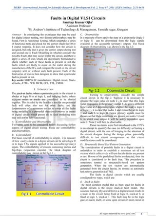
- 1. IJSRD - International Journal for Scientific Research & Development| Vol. 2, Issue 07, 2014 | ISSN (online): 2321-0613 All rights reserved by www.ijsrd.com 3 Faults in Digital VLSI Circuits Sandeep Kumar Ojha1 1 Assistant Professor 1 St. Andrew’s Institute of Technology & Management, Farrukh nagar, Gurgaon Abstract— In considering the techniques that may be used for digital circuit testing, two distinct philosophies may be found, First is Functional Testing, which undertake a series of functional tests and check for the correct (fault free) 0 or 1 output response. It does not consider how the circuit is designed, but only that it gives the correct output during test and second one is Fault Modelling in whichto consider the possible Faults that may occur within the circuit, and then to apply a series of tests which are specifically formulated to check whether each of these faults is present or not.The faults which are likely to occur on the wafer during the manufacture of the ICs, and compute the result on the circuit output(s) with or without each fault present. Each of the final series of tests is then designed to show that a particular fault is present or not. Key words: SBTPG, IC manufacturer, Digital circuit, Stuck- at faults, ATPG, PCB, MCM, ECL, TTL, CMOS I. INTRODUCTION The stuck-at faults, where a particular node in the circuit is always at logic 0 or at logic 1, and bridging faults, where adjacent nodes or tracks are considered to be shorted together. This is aided by the fact that a test for one potential fault will often also test for other faults, and the determination of a minimum test set to cover all the faults being modelled is a powerful objective.However in theory of digital circuit which passes all its fault modelling tests may still not be fully functional. A. Controllability and Observability Two terms need to be considered before discussing further aspects of digital circuit testing. These are controllability and observability. B. Controllability The basic concept of controllability is simple, it is measure of how easily a node in a digital circuit can be set to logic 0 or to logic 1 by signals applied to the accessible (primary) inputs. The controllability of circuits containing latches and flip-flops (sequential circuits) The block diagram of controllability isas shown in the fig.1.1 – C. Observability It is measure of how easily the state of a given node (logic 0 or logic 1) can be determined from the logic signals available at the accessible (primary) outputs. The block diagram of observability is as shown in the fig.1.2- Turning to observability, consider the simple circuit shown in the fig1.2. Suppose it is necessary to observe the logic value on node 2 . In order that this logic value propagates to the primary output Z , to give a different logic value at Z depending upon whether the node is logic 0 or logic 1 , it is clear that nodes 1 and 4 must be set to logic 1 and node 6 to logic 0. Hence primary signals must be chosen so that these conditions are present on nodes 1,4 and 6, in which case output Z will be solely dependent upon node 2. Node 2 will then be observable. These two terms were first introduced in the 1970’s in an attempt to quantify the ease (or difficulty) of testing a digital circuit, with the aim of bringing to the attention of the circuit designer during the design phase potentially difficult to test circuit arrangements so that circuit modifications could be considered. D. Structurally Based Test Pattern Generation The consideration of possible faults in a digital circuit is undertaken in order to establish a minimum set of test vectors which collectively will test that the faults are present or not. If none of the predefined faults are detected, then the circuit is considered to be fault free. This procedure is sometimes termed as structurally-based test pattern generation. When the test vectors are automatically generated from the circuit layout, its termed as automatic test pattern generation (ATPG). The faults in digital circuits which are usually considered two types, which are: E. Stuck-at faults The most common model that as been used for faults in digital circuits is the single stuck-at fault model. This assumes that any physical defect in a digital circuit results in a node in the circuit being fixed at logic 0, stuck-at 0, or fixed at logic 1, stuck-at 1. This fault may be in the logic gate or macro itself, or some open circuit or short circuit in
- 2. Faults in Digital VLSI Circuits (IJSRD/Vol. 2/Issue 07/2014/002) All rights reserved by www.ijsrd.com 4 the interconnections such that the node can no longer switch between 0 and 1. By expression which are as follows— Fault at logic 0---stuck-at 0---s-a-0 And Fault at logic 1--- stuck-at-1---s-a-1 A stuck-at fault is a particular fault model used by fault simulators and automatic test pattern generation (ATPG) tools to mimic a manufacturing defect within an integrated circuit (ICs). Individual signals and pins are assumed to be stuck at Logical '1', '0' and 'X'. For example, an output is tied to a logical 1 state during test generation to assure that a manufacturing defect with that type of behavior can be found with a specific test pattern. Likewise the output could be tied to a logical 0 to model the behavior of a defective circuit that cannot switch its output pin. Not all faults can be analyzed using the stuck-at fault model. Compensation for static hazards, namely branching signals, can render a circuit untestable using this model. Also, redundant circuits cannot be tested using this model, since by design there is no change in any output as a result of a single fault. F. Bridging Faults Unlike stuck-at faults, where a node is considered to be stuck-at one or other logic value, bridging faults may result in a node driven to 0 or 1 by the action at some other node(s) . Since this depends upon the driving impedance of the logic signals on the lines which are bridged, no precise decisions can be made on what the effect of bridging faults will be without some consideration of (i) the technology, (ii) where the faults are in the circuit layout and (iii) how extensive is the bridging. For example—In TTL, logic 0 signal dominate, in ECL, logic 1 signal dominate, and in CMOS Intermediate logic used. When shorted nodes individually have the same logic value (0 or 1) then the circuit outputs will be correct and no fault can be observed. G. The number of bridging faults between any two lines in a circuit of n lines is: n(n-1)/2 Suppose if there are two nodes a andb, if action will be taken on a (logic 1), then b should be at (logic 0). Similarly, if no action will be taken on a (logic 0), then b should be at (logic 1). H. Intermittent Faults Nonpermanent faults in a circuit orsystem are faults that appear and disappear in a random way . Such faults are known as Intermittent faults. Therefore no predetermined set of tests which can be formulated to detect such malfunctioning. It has been reported that a major portion of digital system faults when in service are intermittent (temporary or nonpermanent) faults, and that the investigation of such faults accounts for more than 90% of total maintenance expenditure. Nonpermanent faults may be divided into two categories, namely: 1) Transient Faults which are nonrecurring faults generaly caused by some extraneous influence such as cosmic radiation, power supply surges or electromagnetic interference. 2) Intermittent Faults Which are caused by some imperfection within the circuit or system and which appear at random intervals. I. Digital Test Pattern Generation The final objective of testing is to prevent faulty circuits from being assembled into equipment, or to detect circuits which have developed faults subsequent to their commitment of LSI/VLSI circuits, but apply equally to digital systems which have comparable controllability and observability limitations. The block diagram of Digital Test Pattern Generation (DTPG) are shown in the fig.1.3- There are two probabilities are first introduced, which are – The probability, when fault fi is present in the circuit =PFi The probability, when fault a fi which is active (Ai) is present in the circuit =PAi Then according to Fault Probability Distribution theorem- m ∑ PFi=1 i=1 Digital testing may be considered to have three purpose, namely: J. Fault Detection To discover something wrong in a circuit or system, ideally before it has caused any trouble.Fault detection is a subfield of control system which concerns itself with monitoring a system, identifying when a fault has occurred, and pinpointing the type of fault and its location. Two approaches can be distinguished: A direct pattern recognition of sensor readings that indicate a fault and an analysis of the discrepancy between the sensor readings and expected values, derived from some model K. Physical Fault Location To location of the source of a fault within an integrated circuit. In some cases (e.g., Printed Crcuit Board (PCB), Multi Chip Module (MCMs), embedded or stand-alone memories, it may be possible to repair a failing circuit under test. L. Component Fault Location To location of a faulty component or connection within a completed system. The connection fault location diagram are shown in the fig.1.4 (a) and (b)-
- 3. Faults in Digital VLSI Circuits (IJSRD/Vol. 2/Issue 07/2014/002) All rights reserved by www.ijsrd.com 5 Early methods of fault simulation considered single stuck-at faults one at a time. If there were f possible single stuck-at faults to be considered, then f computer models of the circuit under test were generated, each containing one fault source and a count t, made of the number of faulty circuits which were not detected by the proposed test set. From this procedure a value for the fault coverage TC, of the proposed test set was calculated using the equation: TC = (f-t) / f * 100 % Where, TC =Test coverage or Fault Coverage f = The possible single stuck at fault t = The number of faulty circuits which were not detected by proposed test set. M. Roth’s D-algorithm Routh’s D-algorithm forms the underlying concept of the many practical ATPG programs.It sensitises all paths from the site of a chosen fault to an observable output and uses for 1000 gates.Its operate at individual gate level and requires knowledge of all gates and their interconnection topology. The D-algorithm involves five logic states, namely: 0 = Normal logic zero 1 = Normal logic one D =1 fault free condition D =0 Fault chosen condition X = an unassigned logic value, which can take any value 0, 1 or D Thus D identifies a line or node which is 1 under fault-free conditions and changes to 0 under the fault chosen conditions. II. CONCLUSION It introduced the basic concept of controllability and observ ability of nodes within a digital circuit, but has shown that quantification of these two parameters does not have a great practical significance, particularly for VLSI circuits. Modelling the faults that can arise in digital circuits, with a view to establishing tests which specifically detect whether such faults are present or not, has a longer records of success, the stuck-at fault model particularly significant. III. ABBREVIATION DTPG (Digital Test Pattern Generation) SBTPG (Structurally Based Test Pattern Generation) VLSI (Very Large Scale Integration) MCM (Multi Chip Module) ECL (Emitter Coupled Logic) ATPG (Automatic Test Pattern Generation) TTL (Transistor Transistor Logic) REFERENCES [1] Abramovici, M., Breuer, M.A., And Friedman : Digital Systems Testing And Testable Design. [2] Lala, P.K. Fault Tolerant And Fault Testable Hardware Design. [3] Wilkins, B.R. : Testing Digital Circuits An Introduction. [4] Fujiwara, H : Logic Testing And Design For Testability. [5] Miczo, A : Digital Logic Testing And Simulation. [6] Pynn, C : Strategies For Electronic Test. [7] Stevens, A.K. :Introduction To Component Testing. [8] Parker , K.P. : Integrating Design And Test: Using Cae Tools. [9] Yarmolik, V.N.: Fault Diagnosis Of Digital Circuits. [10]Bennetts,R.G.: Design Of Logic Circuits. [11]Bateson, J.: In-Circuit Testing. [12]Miller, D.M.: Developments In Integrated Circuit Testing. [13]Williams, T.W.: Vlsi Testing. [14]Hurst, S.L.: Custom Vlsi Microelectronics. [15]Di Giacomo, J.: Designing With High Performance Asics. [16]Mei, K.C.Y.: ‘ Bridging And Stuck-At Faults’