A Study on 3D Finite Element Analysis of Anterior Cruciate Ligament Behavior on Full Extension

The present study deals with the force and stress distribution within the anteromedial (AM) and posterolateral (PL) bundles of the anterior cruciate ligament (ACL) in response to an anterior tibial load with the knee at full extension was calculated using a validated three dimensional finite element model (FEM) of a human ACL. The interaction between the AM and PL bundles, as well as the contact and friction caused by the ACL wrapping around the bone during knee motion, were included in the model. The AM and PL bundles of the ACL were simulated as incompressible homogeneous and isotropic hyperelastic materials. The validated FEM was then used to calculate the force and stress distribution within the ACL under an anterior tibial load at full extension. The AM and PL bundles shared the force, and the stress distribution was non-uniform within both bundles with the highest stress localized near the femoral insertion site. The contact and friction caused by the ACL wrapping around the bone during knee motion played the role of transferring the force from the ACL to the bone, and had a direct effect on the force and stress distribution of the ACL. This validated model will enable the analysis of force and stress distribution in the ACL in response to more complex loading conditions and has the potential to help design improved surgical procedures following ACL injuries.

Recommended
More Related Content
What's hot
What's hot (20)
Similar to A Study on 3D Finite Element Analysis of Anterior Cruciate Ligament Behavior on Full Extension
Similar to A Study on 3D Finite Element Analysis of Anterior Cruciate Ligament Behavior on Full Extension (20)
More from ijsrd.com
More from ijsrd.com (20)
Recently uploaded
Recently uploaded (20)
A Study on 3D Finite Element Analysis of Anterior Cruciate Ligament Behavior on Full Extension
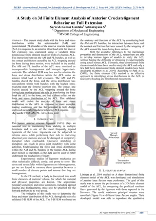
- 1. IJSRD - International Journal for Scientific Research & Development| Vol. 2, Issue 09, 2014 | ISSN (online): 2321-0613 All rights reserved by www.ijsrd.com 299 A Study on 3d Finite Element Analysis of Anterior Cruciateligament Behavior on Full Extension Sarvesh Kumar Gantala1 Adinarayana S2 1,2 Department of Mechanical Engineering 1,2 MVGR College of Engineering Abstract— The present study deals with the force and stress distribution within the anteromedial (AM) and posterolateral (PL) bundles of the anterior cruciate ligament (ACL) in response to an anterior tibial load with the knee at full extension was calculated using a validated three dimensional finite element model (FEM) of a human ACL. The interaction between the AM and PL bundles, as well as the contact and friction caused by the ACL wrapping around the bone during knee motion, were included in the model. The AM and PL bundles of the ACL were simulated as incompressible homogeneous and isotropic hyperelastic materials. The validated FEM was then used to calculate the force and stress distribution within the ACL under an anterior tibial load at full extension. The AM and PL bundles shared the force, and the stress distribution was non-uniform within both bundles with the highest stress localized near the femoral insertion site. The contact and friction caused by the ACL wrapping around the bone during knee motion played the role of transferring the force from the ACL to the bone, and had a direct effect on the force and stress distribution of the ACL. This validated model will enable the analysis of force and stress distribution in the ACL in response to more complex loading conditions and has the potential to help design improved surgical procedures following ACL injuries. Keywords: FEM, AM, PL, ACL, Knee joint I. INTRODUCTION The human anterior cruciate ligament (ACL) plays an essential role in maintaining knee stability in multiple directions and is one of the most frequently injured ligaments of the knee. Ligaments can be subjected to extreme stress while performing their role in restricting abnormal joint motions and can be damaged or completely disrupted when overloaded. Excessive stretching or disruption can result in gross joint instability with some activities. Understanding the force and stress distribution within the AM and PL bundles of the human ACL during knee motion is important, as the data can be used to better understand the mechanism of injury. Experimental studies of ligament mechanics are often technically difficult, costly, and prone to error. The stress and strain fields within ligaments are inhomogeneous, yet we are forced to measure these quantities between a small number of discrete points and assume that they are homogeneous. In the FE method, a body is discretized into small finite elements of material volume, for which the material and physical properties are known. The appropriate boundary conditions and initial conditions, including applied loading and displacements, must also be specified for the forward problem to be well posed. The objective of this study was to determine the force and stress distribution of the ACL through the use of a validated 3-D FEM of the ACL. The 3-D FEM was based on the anatomy and function of the ACL by considering both the AM and PL bundles, the interaction between them, and the contact and friction that were caused by the wrapping of the ACL around the bone during knee motion. With the available references to the mechanical properties and dimensions of the ACL, researchers are able to develop various types of models to study the ACL without having the difficulty of obtaining it experimentally using actual human ACL. Currently, three dimensional finite element models have been used to study the ACL and only a few full three dimensional finite element models have been developed (Limbert et al. 2004). According to Park et al. (2010), the finite element (FE) method is an effective approach in identifying stress distributions in the ACL in reaction to loading and tibiofemoral movements. II. LITERATURE SURVEY Limbert et al. 2004 studied on A three dimensional finite element model of the ACL was developed and simulations of passive knee flexion were performed. The goal of this study was to assess the performance of a 3D finite element model of the ACL, by comparing the predicted resultant force generated by the ligament with those reported in the literature. The result maximum principal stresses were recorded (Figure 9) at different knee flexion angles. Their developed model was able to reproduce the qualitative
- 2. A Study on 3d Finite Element Analysis of Anterior Cruciateligament Behavior on Full Extension (IJSRD/Vol. 2/Issue 09/2014/068) All rights reserved by www.ijsrd.com 300 mechanical behaviors of the ACL and the quantitative data from cadaver testing. Park et al. 2010 study was to develop a FEM of the ACL to conduct finite element analysis (FEA) on the ACL impingement against the intercondylar notch under tibial external rotation and abduction. The FEA showed that impingement between the ligament and the lateral wall of intercondylar notch could occur when the knee at 45° was externally rotated at 29.1° and abducted at 10.0°. Their results showed that the impingement force increased as the abduction and external rotation increased. Peña et al. 2006 study developed a three dimensional FEM of the human knee that includes the femur, tibia, articular cartilage, menisci and ligaments (patellar tendon, anterior cruciate, posterior cruciate, medial collateral and lateral collateral). Their model was used to study the kinematics and stresses. A combination of 1150 N compressive load, 10 Nm valgus torque and a 134 N anterior load were applied to their model. The FEM and the maximum principal stresses in the ligaments are shown in Figure 11. Song et al. 2004 Studied the force and stress distribution on the ACL with a 134N anterior tibial load at full extension, and their goal was to determine the feasibility of developing a FEM of the human ACL. This goal was accomplished as the FEM was developed, validated and the force and stress distribution within the ACL was determined. They found that the stress distribution on the ACL during a 134N anterior tibial load at full extension was not uniform throughout the ACL. The highest stress was found to be located near the femoral intersection area as the ACL wraps around the bone when load is applied. Yao et al. 2005 studied about the menisci are believed to play a stabilizing role in the ACL-deficient knee, and are known to be at risk for degradation in the chronically unstable knee. Much of our understanding of this behavior is based on ex vivo experiments or clinical studies in which we must infer the function of the menisci from external measures of knee motion. More recently, studies using magnetic resonance (MR) imaging have provided more clear visualization of the motion and deformation of the menisci within the tibio-femoral articulation. In this study, we used such images to generate a finite element model of the medial compartment of an ACL- deficient knee to reproduce the meniscal position under anterior loads of 45, 76, and 107N. Comparisons of the model predictions to boundaries digitized from images acquired in the loaded states demonstrated general agreement, with errors localized to the anterior and posterior regions of the meniscus, areas in which large shear stresses were present. Our model results suggest that further attention is needed to characterize material properties of the peripheral and horn attachments. Although overall translation of the meniscus was predicted well, the changes in curvature and distortion of the meniscus in the posterior region were not captured by the model, suggesting the need for refinement of meniscal tissue properties. Pena et al. 2004. presented and discussed the results obtained with a three-dimensional finite element model of the human knee joint corresponding to different aspects of human anterior cruciate ligament reconstruction. In particular, this model was used to investigate the effect of graft stiffness and graft tensioning on the knee joint biomechanics. The initial graft tension was set to 0, 20, 40 or 60 N with the knee at 0°, 30° and 60° of flexion. Three different stiffnesses corresponding to those of patellar tendon, gracilis and quadrupled semitendinosus grafts were analyzed. III. MATERIAL AND METHODS A. Generation of Finite Element Model of the ACL The finite element model includes the femur, tibia, the ACL. The 3D geometry of the femur and tibia was obtained from the MRI data. The 3D geometry of the ACL was modeled using SOLIDWORKS. To construct a three dimensional model of the two ligaments, assumptions were made and the mechanical properties, anatomical properties and dimensions were applied. B. Assumptions For this model two assumptions are made and they are as follows, (1) The ligament and bone material are considered isotropic. Therefore the material properties of the body and insertion site of the ACL are the same. (2) The viscoelasticity, creep, and relaxation are neglected due to high ratio between viscoelastic time constant and loading time. C. Mechanical Properties There are two main types of materials involved in this FEM. They are the bone and ligament. The mechanical properties for both these materials were applied. The femur and tibia were applied with the bone material. The ACL and PCL were applied with the ligament material. The chart with the bone and ligament mechanical properties is shown. Properties Materials Bone Ligament Density (kg/m 3 ) 1900 -- Yield Strength (MPa) 80 -- Ultimate Strength (MPa) 130 70 Elastic Modulus (GPa) 17 0.40 Shear Modulus (GPa) 3.3 -- Poissons Ratio 0.40 0.40 Table: Mechanical Properties of the Bones and Ligament (Ozkaya & Nordin 1999) Chandrashekar et al.’s (2006) studied in the differences in tensile properties of the human ACL, they were able to test multiple human ACLs from both male and female cadavers, their results were compared with the ACL studies of Woo et al. (1991) and Noyes and Grood (1976). From Chandrashekar et al.’s study, noticeable differences in male and female ACLs have been seen. In mechanical properties, the modulus of elasticity and stiffness is much greater in male than female ACL. The stress, strain, and load at failure are seen to be greater in male than female ACL. For the dimensions of the ACL, the length and cross sectional area of the male ACL is also greater than the female ACL. The additional mechanical properties of the model ACL are based on the mechanical properties measured by Chandrashekar et al (2006), shown in Table. And the mechanical properties of the PCL are obtained from Prietto et al. (1988) shown.
- 3. A Study on 3d Finite Element Analysis of Anterior Cruciateligament Behavior on Full Extension (IJSRD/Vol. 2/Issue 09/2014/068) All rights reserved by www.ijsrd.com 301 Study Chandrashekar et al 2006 Elongation at failure (mm) 8.95 ± 2.12 Strain at Failure 0.30 ± 0.06 Load at failure (N) 1818 ± 699 Stress at failure (MPa) 26.35 ± 10.08 Stiffness (N/mm) 308 ± 89 Modulus of Elasticity (MPa) 128 ± 35 Table: Mechanical Properties of the ACL D. Dimensions The ACL was modeled using the dimensions measured by Chandrashekar et al.’s (2005) study. A table of the measurements is shown in Table 6. And the PCL was modeled using the dimensions measured by Harner et al. (1999) and Prietto et al. (1988) shown. Study Chandrashek ar et al 2006 Length(mm) 29.82 ± 2.51 Mid Substance(mm 2 ) 83.54 ± 24.89 Femoral Insertion Width (mm) -- Femoral Insertion Length (mm) -- Tibial Insertion Width (mm) -- Tibial Insertion Length (mm) -- Table: Dimensions of the ACL E. Boundary Conditions Boundary conditions are then applied onto the model for finite element analysis. The femur is rigidly fixed as the tibia is free to move in the flexion plane, as well as the varus/valgus and internal/external rotations. Three contact zones are also applied. First is a frictionless contact zone set between the base of the femur with the cranial portion of the tibia. Second is a bonded contact zone between the ACL and the femoral insertion site. The third is also a bonded contact zone between the ACL and the tibial insertion site. F. Finite Element Analyses With the mechanical and anatomical properties, forces, and boundary conditions applied onto the model, finite element analyses were performed. Each analysis tests a different risk factor. These analyses were conducted using ANSYS Workbench v.13 software. And the steps in applying the risk factors are as follows. G. Ligament Size To examine the stress on the ACL according to size, the size of the ACL was varied in increments of 3mm. According to Chandrashekar et al. (2005), the average size of the male ACL is 29.82mm and 26.85mm for females. The sizes of ligament tested were in the range of 24-33mm. This range is chosen to test ligament sizes greater and less than the average ligament sizes of male and female ACLs. H. Finite Element Model of the Knee The assembled CAD model of the knee inputted into ANSYS was setup and meshed to conduct finite element analyses. Notice that the generated number of elements for the femur is less than the tibia for the meshed model. This is because the original CAD model of the femur consists of fewer faces than the tibia. Also the number of elements is reduced due to the extensive run time it requires to generate the mesh and run analyses. The greater the number of elements the model consists of the longer the run time. I. Evaluation of the Finite Element Model To evaluate the model, the model was compared with the nmodel developed by Peña et al. (2006). The study applied a 134N anterior tibial load and a compressive load of 1150N at full extension of the knee. Identical loads were applied onto the constructed model. The results were then compared with the results from Peña et al.’s study (2006). The results did not turn out to be the same. The results obtained for the maximum principal stress on the ACL were lower than the values obtained from Peña et al.’s study. Peña et al.’s study reported an average maximum principal stress of around 6.5 MPa and a maximum of 15 MPa. The difference in result values seen in the comparison with Peña et al.’s study (2006) may be due to the lack of anatomical structures. Peña et al.’s model incorporates all four knee ligaments as well as the meniscus. This may cause loads on the ACL to be shared by other ligaments. The mechanical properties used for Peña et al.’s study may have been different from the ones obtained for this model. Another reason for the difference in value may be because of the ACL model used. The ACL model used in Peña et al.’s study was generated using data collected from magnetic resonance imaging (MRI) while the ACL model in this study was modeled in ProENGINEER using parameters and information proposed by Chandrashekar et al. (2005) and Harner et al.
- 4. A Study on 3d Finite Element Analysis of Anterior Cruciateligament Behavior on Full Extension (IJSRD/Vol. 2/Issue 09/2014/068) All rights reserved by www.ijsrd.com 302 IV. CONCLUSIONS Computational models of ligaments offer the potential to provide information regarding ligament mechanics that would be difficult or impossible to measure experimentally. The complex material properties of ligaments make the accurate modeling of their material behavior a challenge. In the present work, i have provided a critical review of the constitutive models that have been developed to represent ligaments and tendons. These models have developed from rather simplistic descriptors of one-dimensional behavior to models capable of describing and predicting three- dimensional isotropic behavior. The objective of these modeling efforts is to improve the clinical diagnosis and treatment of ligament injuries. The models may also identify means by which to prevent injuries, such as through the use of protective equipment in the case of sports-related injuries. REFERENCES [1] Limbert, G., Taylor, M., & Middleton, J. (2004). Three-dimensional finite element modeling of the human ACL: Simulation of passive knee flexion with a stressed and stress-free ACL. Journal of Biomechanics, 37(11), 1723-1731. [2] Park, H., Ahn, C., Fung, D. T., Ren, Y., & Zhang, L. (2010). A knee-specific finite element analysis of the human anterior cruciate ligament impingement against the femoral intercondylar notch. Journal of Biomechanics, 43(10), 2039-2042. [3] Peña, E., Calvo, B., Martínez, M. A., & Doblaré, M. (2006). A three-dimensional finite element analysis of the combined behavior of ligaments and menisci in the healthy human knee joint. Journal of Biomechanics, 39(9), 1686-1701. [4] Jiang Yao, Jason Snibbe, Michael Maloney and Amy L. Lerner, Stresses and Strains in the Medial Meniscus of an ACL Deficient Knee under Anterior Loading: A Finite Element Analysiswith Image-Based ExperimentalValidation,, JBiomech Eng 128(1), 135-141, Sep 14, 2005. [5] Chandrashekar, N., Mansouri, H., Slauterbeck, J., & Hashemi, J. (2006). Sex-based differences in the tensile properties of the human anterior cruciate ligament. Journal of Biomechanics, 39(16), 2943- 2950. [6] Prietto, M., Bain, J., Stonebrook, S., & Settlage, R. (1988). Tensile strength of the human posterior cruciate ligament (PCL). Trans Orthop Res Soc, 13(195), 736-745. [7] Harner, C. D., Baek, G. H., Vogrin, T. M., Carlin, G. J., Kashiwaguchi, S., & Woo, S. L. Y. (1999). Quantitative analysis of human cruciate ligament insertions. Arthroscopy: The Journal of Arthroscopic & Related Surgery, 15(7), 741-749. Woo, S. L. Y., Hollis, J. M., Adams, D. J., Lyon, [8] R. M., & Takai, S. (1991). Tensile properties of the human femur-anterior cruciate ligament-tibia complex. The American Journal of Sports Medicine, 19(3), 217. [9] Noyes, F. R., & Grood, E. S. (1976). The strength of the anterior cruciate ligament in humans and rhesus monkeys. The Journal of Bone and Joint Surgery. American Volume, 58(8), 1074-1082. Retrieved from http://www.jbjs.org/article.aspx?Volume=58&pa ge=1074.