1. Andrew Rusinko Int. Journal of Engineering Research and Applications www.ijera.com
ISSN : 2248-9622, Vol. 4, Issue 3( Version 1), March 2014, pp.172-180
www.ijera.com 172 | P a g e
Feigen’s Phenomenon in Terms of the Synthetic Theory
Andrew Rusinko
Obuda University, Népszínház St. 8, Budapest, Hungary, H-1081
Abstract The paper concerns with the analytic description of Feigen’s results on plastic straining under
combined loading. The model is developed in terms of the synthetic theory of irrecoverable deformation.
Criterion to establish when Feigen’s phenomenon can be observed is proposed. It is worthwhile to note that the
synthetic theory requires no special additional assumptions, or generalizations to model Feigen’s experiment.
Keywords: Feigen’s phenomenon, plastic deformation, combined loading, synthetic theory of irrecoverable
deformation
I. Introduction
Feigen’s experimental results (Feigen, M., 1954) are of crucial importance to obtain further insight into
mechanisms of plastic deforming. Despite the fact that this phenomenon dates back to the 1950s of the twentieth
century, its modeling has not been completely solved yet.
Consider Feigen’s experiment consisting in the following loading regime:
(i) a specimen plastically deforms in a complex stress state, tension and torsion (Fig. 1a);
(ii) the torsional component decreases and the tension increases, (Fig. 1b). The loading path (ABC, >AC AB) is
shown in Fig. 2.
Feigen reports an unexpected phenomenon is observed. The torsional plastic deformation ( S
)
accumulated in the initial combined loading decreases during the torsional unloading, 0S
along BC
portion: the specimen is plastically “untwisting”. According to classical ideas, a plastic strain developed in
active loading remains unchangeable during the succeeding unloading.
This phenomenon can be explained by the fact that, along portion BC, plastic shifts develop within such slip
systems that give negative increment in torsional strain thereby resulting in the plastic untwisting of specimen.
At the same time, the fraction of grains, which produced positive torsional strains along portion AB, remains
hardened along BC.
The aim of the paper is to model Feigen’s experiments in terms of the synthetic theory of recoverable
deformation. Another goal of the study is to establish a criterion for predicting the condition when the
phenomenon is manifested. It is worth noting that the synthetic theory needs no additional assumptions or
generalizations; its classical statement is readily applicable to the analytical description of Feigen’s results. In
contrast, for example, Mazilu, P. (1985) tried to explain this phenomenon by assuming the existence of certain
hypoelastic deformations (Lehmann, Th., 1962) accompanying the elasto-plastic one.
The research presented here may be of interest for the studies dealing with a wide variety of engineering
mechanics (Mirsalimov and Veliyev (2013); Szekeres (2012); Kharchenko and Sobkowski (2005); Zabłocka et
al. (2012); Malinin, V. (2011)).
It is clear that Feigen’s phenomenon can not be modeled in terms of classical flow plasticity theories
(for an extensive review, see Rees, 1987). If we take, for example, flow plasticity theory with isotropic
hardening rule, it will relate plastic strain tensor components increment ( S
ijd ) to stress deviator tensor
components ( ij ) as
0 0
S
ij ijd C d , (1.1)
where 0 is the second invariant of stress tensor and 0C is
0
0
1 1 1
2 t
C
G G
, (1.2)
where G is elastic shear modulus and 0 03tG d d ( 0 is the second invariant of strain tensor). Condition
tG G implies that 0 0C .
RESEARCH ARTICLE OPEN ACCESS
2. Andrew Rusinko Int. Journal of Engineering Research and Applications www.ijera.com
ISSN : 2248-9622, Vol. 4, Issue 3( Version 1), March 2014, pp.172-180
www.ijera.com 173 | P a g e
For the case of biaxial loading (tension + torsion), Eq. (1.1) give
0 0
S
d C d , 0 0
S
d C d . (1.3)
In terms of the flow theory with isotropic hardening, plastic deformation is assumed to develop if 0 0d . If to
suggest that 0 0d along portion BC ( 0 and 0 ), then Eq. (1.3) gives positive increments in both S
and S
components. For the case 0 0d , we have 0S S
d d . Both results contradict Feigen’s
experiment reporting that 0S
d .
II. Mathematical apparatus: the synthetic theory of irrecoverable deformation.
The synthetic theory, which concerns with small strains of work-hardening metals, incorporates the
elements of flow plasticity theory (Sanders, 1954) and slip concept (Budiansky, 1949). The fundamentals of the
synthetic theory are put forth in details in Rusinko’s works (2009, 2011).
(i) The synthetic theory belongs to two-level models. Similarly to the Budiansky slip concept, the synthetic
theory has a micro- and a macro-level. For the macrolevel we take as the elementary volume of the body, ,
which is considered as point in the mathematical sense. The given volume, , consists of a large quantity of
volumes, 0 (the micro-level), each being an element of the continuous, capable of deforming under the applied
forces. Accordingly to Budiansky, it is assumed that the stress state in every volume 0 is the same as that in the
volume . Plastic deformation in the microvolume 0 (grain) is assumed as slip of one part of 0 in relation to
another. Therefore, in contrast to the even distribution of the stress above microvolumes 0, the plastic
deformation (or plastic slip) depends on the orientation of the slip system relative to the direction of the acting
forces. It is assumed that the quantity of 0 is so great (theoretically it tends to infinity) that every possible
orientation of slip systems exists in volume . The total deformation of is determined as the sum of the
components of deformations generated within volumes 0. Lichatchev et al. (1993) give the substantiation of
the sizes of microvolumes 0.
(ii) The establishment of stress~strain relationships on microlevel takes place in the three-dimensional
subspace, R3
, of the Ilyushin five-dimensional stress deviator space, R5
, where a loading is presented by stress
vector, 3
S R
, whose components are
1 3 2 xxS S , 2 2 2xx yyS S S , 3 2 xzS S , (2.1)
where ijS are the stress deviator tensor components. The length of the vector S
is related to the second
invariant of stress deviator tensor ( 2J ) as 22 3JS
.
(iii) New yield criterion is introduced, which coincides with nor Tresca’s, no von-Mises’s one in R5
. At the
same time, its trace in 3
R gives the von-Mises yield criterion:
2 2 2 2
1 2 3 SS S S S , 2 3S SS (2.2)
where S is the yield strength of material in uniaxial tension. Through each point on the sphere we draw a
tangent plane. So, the yield surface can be thought of the inner envelope of equidistant planes. The position of
plane in 3
R is defined by the following two quantities (Fig. 3):
a) Unit vector 1 2 3( , , )m m mm
normal to the plane:
1 cos cosm , 2 sin cosm , 3 sinm , (2.3)
where α and β are spherical angles giving the orientation of m
in 3
R (Rusinko, 2009). For simplicity, we
consider only planes tangential to yield/loading surface in 3
R and those tangential to the yield/loading surface
in 5
R are ignored.
b) The distance from the origin of coordinates to the plane, mh .
The condition that a plane is located on the endpoint of stress vector is expressed as
mh S m
. (2.4)
(iv) According to Sanders, to establish a hardening rule, we extend the provision that a surface is constructed as
an inner envelope of planes to the case of loading as well. During loading, the vector S
displaces on its
endpoint a set of planes from their initial position, i.e. from sphere (2.2). Each plane moves without changing its
3. Andrew Rusinko Int. Journal of Engineering Research and Applications www.ijera.com
ISSN : 2248-9622, Vol. 4, Issue 3( Version 1), March 2014, pp.172-180
www.ijera.com 174 | P a g e
orientation. As a result, the loading surface – an inner envelope of planes – has a form as shown in Fig. 4. It
consists of
- a cone whose lateral surface is formed by the boundary planes reached by the S
and
- the part of sphere (2.2), which is the inner envelope of stationary planes.
(v) Each tangent plane corresponds to an appropriate slip system, and the displacement of the plane on the
endpoint of stress vector symbolizes the development of plastic microdeformation within the slip system. Plastic
microstrain modeled by the displacement of one plane is assumed to be a vector normal to the plane (see Fig. 3).
It is easy to see that the distance to a plane gives the degree of the hardening of material. Indeed, the greater mh ,
the greater stress vector is needed to reach the plane, i.e. to induce plastic shift within the corresponding slip
system. Further, we introduce an average measure of plastic strain developed within a slip system (i.e. for one
plane), termed as plastic strain intensity ( m ), as follows
2 2
if (plane is reached by )1
0 if (plane is not reached by )
m S m
m
m
h S h
r h
S m S
S m S
(2.5)
where r is the constant of material, 2
MPar . It must be noted that the product S m
is the resolve stress
acting within a slip system. Further, it is easy to see that the greater mh , the greater distance is traveled by the
plane on the endpoint of stress vector, i.e. the greater plastic deformation develops within the corresponding slip
system.
(vi) The macroplastic deformation, expressed via plastic strain vector components ( S
ke ), is calculated as the sum
of non-zero m (Rusinko, 2009, 2011):
S S
md dV
e e m
, or S
k m ke m dV
, cosdV d d , 1,2,3k . (2.6)
The components ke from Eq. (2.6) can be converted to the strain deviator tensor components ( ije ) as
1 3 2 xxe e , 2 2 2xx yye e e , 3 2 xze e (2.7)
It must be noted that, in terms of the synthetic theory, both loading and deformation are expressed via vectors:
S
and S
e
, respectively. It is clear that vector algebra is much easier than tensor analysis. One more point that
deserves attention is that vector components iS have the same rights in the criterion (2.2); it is not the case if the
von-Mises yield criterion is expressed via, e.g., stress deviator tensor components:
1 2
2 2 2 2 2 2
22 2 3xx yy zz xy yz xzS S S S S S J
.
III.Isotropy postulate in terms of the synthetic theory
According to Ilyushin (1963), isotropy postulate reads that if the stress path in 3
R is rotated in stress
deviator space, then the corresponding strain path is rotated by the same amount (this postulate is valid for only
von-Mises’s medium). Consider an arbitrary loading path in 3
R as shown in Fig. 5. Let the corresponding strain
vector be e
, which makes angle η with the stress vector S
. Now, we rotate the loading path by a certain angle,
δ. To demonstrate the fulfillment of the isotropy postulate, we rotate the coordinate system by the same angle δ.
Within the rotated coordinate system, we obtain an analog of the previous loading and, therefore, it is easy to
conclude that the angle between vectors e
and S
must be the same as in the initial case. It is clear that the value
of strain strongly depends on the inner geometry of the loading path, but the rotation of loading path as a rigid
figure does not affect the relation between vectors e
and S
at any point of loading path.
IV. Feigen’s phenomenon in terms of synthetic theory
Relying upon isotropy postulate, we can model Feigen’s phenomenon. We consider the following case:
(i) an initial biaxial loading is proportional, i.e. the loading path of the stress vector S
is a straight line and (ii)
after the loading an infinitesimal orthogonal additional loading is applied ( d S S
). It is clear that such a
loading regime falls within the scope of Feigen’s experiment due to the additional loading gives an increase in
tension and decrease in torsion. Let the vector S
make angle with 1S -axis. Let us introduce a new system of
4. Andrew Rusinko Int. Journal of Engineering Research and Applications www.ijera.com
ISSN : 2248-9622, Vol. 4, Issue 3( Version 1), March 2014, pp.172-180
www.ijera.com 175 | P a g e
coordinates ( 1 2 3' ' 'S S S ) by rotating the initial system by the angle so that the stress vector is along the 1 'S -
axis. In fact, we obtain an analog of two-segment loading, uniaxial tension and additional torsion. Consequently,
according to isotropy postulate, techniques developed in Rusinko’s previous works (2009, 2011) can be readily
used. In terms of the rotated coordinate system, the stress vector for the initial portion of loading has the only
nonzero component:
1 ' 2 3 'xS , 2 ' 0S 3 ' 0S , SSS
. (4.1)
On the base of Eqs. (2.3)-(2.5), the distance to plane and strain intensity are
1 1' ' ' 2 3 'cos 'cos 'm xh S m , (4.2)
2 2 2 22
' ' cos 'cos '
3
m x S
r
, (4.3)
where angles ' and ' are measured within 1 2 3' ' 'S S S coordinate system in the same way as within the
original system. The only non-zero component of plastic strain vector S
e
in 1 2 3' ' 'S S S coordinate system is (by
analogy with calculations from Rusinko’s works (2009, 2011))
1 1
1 1
2 2 2 2 2
1 1
' '
2
' ' ' ' cos 'cos ' cos 'cos ' ' '
3
S
m x Se m dV d d
r
, (4.4)
where
1cos '
cos '
b
, 1cos b ,
'
S
x
b
. (4.5)
By integrating (4.4) over domain (4.5) we obtain
2
1
4
'
3
S S
e b
r
,
2
2
2
1
1b b
b
, 1 0 . (4.6)
Due to the action of dS
, which is analogous to additional torsion ( 'xzd ) within 1 2 3' ' 'S S S coordinate system,
the strain intensity acquires the following increment
' 2 ' 'm m mrd h dh , (4.7)
where
' ' ' 2 sin ' 'm m m xzdh h h d , (4.8)
where 'mh stands for the distance to planes under the action of dS S
vector:
' 2 3 'cos 'cos ' 2 sin ' 'm x xzh d . (4.9)
As follows from the analysis of two segment orthogonal loading (Rusinko, 2009), plastic strain vector increment
components, 1 'S
de and 3 'S
de , are calculated as
1 1
1
2 3
1 1
' ' 0
4 ' '
' ' ' cos 'cos 'sin ' ' '
3
S x xz
m
d
de d m dV d d
r
, (4.10)
1 1
1
2 2
3 3
' ' 0
4 ' '
' ' ' cos 'cos 'sin ' ' '
3
S x xz
m
d
de d m dV d d
r
, (4.11)
Comparison of Eqs. (4.10) and (4.11) to Eq. (4.4) – ' -domain is 10, and 1 1, , respectively – shows
that the set of planes being at the endpoint of S
vector is two times less than that due to the action of dS S
.
Integrating in (4.10) and (4.11) yields
2
1 ' '
3 '
S S
xz
x
de b d
r
, 2
2
1 1
arccos 1 1 2b b b b
bb
, (4.12)
5. Andrew Rusinko Int. Journal of Engineering Research and Applications www.ijera.com
ISSN : 2248-9622, Vol. 4, Issue 3( Version 1), March 2014, pp.172-180
www.ijera.com 176 | P a g e
1
3
3 '
' '
2 '
S
S
xz
x
e
de d
. (4.13)
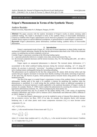
The plot of b is shown in Fig. 6. As we can see from the formulae above, the value of strain
increments strongly depends on the value of initial loading.
The set of planes displaced by the vector S
is shown in Fig. 7a. For the case when the loading path of the vector
S
is a straight line (proportional loading) (i) the normal vectors of displaced planes are symmetric above 1 'S -
axis, (ii) planes on either side of the S
incurs identical displacements. This means that the total plastic strain
vector S
e
, which is calculated as the sum of strain vectors, each of which is normal to the plane displaced by
the S
, lies along the 1 'S -axis.
To model Feigen’s phenomenon, one needs to analyze the sign of 3
S
e
vector during additional loading.
In Fig. 7b, planes with 3 0m are depicted by solid lines; they give positive increments in 3
S
e
caused by an
orthogonal increment in stress. For planes depicted by dashed lines 3 0m , and, consequently, they stand with
negative signs in the sum for the 3
S
e
. It is clear that the sign of 3
S
e
depends on the set of ―positive‖ and
―negative‖ planes and the distances they traveled on the endpoint of stress vector.
The number of planes displaced by additional vector dS
is two times less than under the action of S
(Fig. 7b), and this set of the planes contains the same number of planes with negative normals (i.e. normals with
negative components on 3S -axis), while the number of planes with positive normals halves. This fact implies
that the slope of the strain vector due to the action of dS S
vector is less than that due to the S
vector.
Feigen’s phenomenon, an negative increment in plastic shear deformation during additional loading dS
, is
observed when the sum of plastic deformation increments having negative components on 3S -axis is greater
than that having positive components on 3S -axis.
Now, we wish to establish a criterion for occurring of Feigen’s phenomenon. In other words, we need
to establish such an angle between stress vector S
and 1S -axis, angle in Fig. 8, so that the orthogonal
additional loading results in the negative component of S
de
on 3S -axis, 3 0S
de . By projecting vector
1 3' 'S S S
d d d e e e
on 3S - axis and using Eqs. (4.12) and (4.13), we obtain
3 1 3'sin 'cosS S S
de de de (4.14)
Eq. (4.14) at 3 0S
de , together with (4.12) and (4.13), gives
1
3 1
0 2 2
1
3 '
'
' 2 ' 3 '
tan
' 2
'
3 '
S
xzS S
x
S
S S
xz
x
e
d
de re
de b
b d
r
. (4.15)
If 0 , then 3 0S
de , meaning that Feigen’s phenomenon will be observed. This situation is shown
in Fig. 8a. For the case 0 (Fig. 8b), we have 3 0S
de implying a positive increment in plastic torsional
deformation due to dS
, which contradicts Feigen’s phenomenon.
Therefore, Eq. (4.15) can be treated as a criterion for occurring Feigen’s phenomenon as a function of the
parameters of initial loading.
V. Conclusion
The present paper has modeled Feigen’s phenomenon in terms of the synthetic theory. A condition for
the onset of negative shear plastic strain under the additional loading has been derived. We restrict ourselves to
the case when the additional loading is perpendicular to the initial one. It has been shown that parameters of
initial loading, the orientation and magnitude of stress vector, considerably affects the behavior of specimen
under the second portion of loading.
6. Andrew Rusinko Int. Journal of Engineering Research and Applications www.ijera.com
ISSN : 2248-9622, Vol. 4, Issue 3( Version 1), March 2014, pp.172-180
www.ijera.com 177 | P a g e
References
[1] Batdorf, S., Budiansky, B. (1949). Mathematical theory of plasticity based on the concept of slip.
NACA, Technical note, 871
[2] Feigen, M. (1954), Inelastic behavior under combined tension and torsion, 2nd
USNCAM, pp. 469-476.
[3] Ilyushin, A.A. (1963). Plasticity, Moscow.
[4] Kharchenko, Y., Sobkowski, S. (2005) Modelowanie matematyczne procesów rozruchu układów
napędowych podnośników budowlanych, Diagnostyka, 35: 37-42. (in Polish)
[5] Lehmann, Th. (1962). Zur Besehreibung groBer plastischer Form~nderungen unter Beriicksichtigung
der Werkstoffverfestigung, Rheol. Acta 2: 247-254.
[6] Lichatchev, V., Malinin, V. (1993). Structural-analytic theory of strength, St. Petersburg (in Russian).
[7] Malinin, V. (2011) Structural and analytical criterion of the fragile destruction for matter with
macroconcentration tension, J. Fundamental and Applied Problems of Engineering and Technology, 2:
36-42.
[8] Mazilu, P. (1985). Decreasing of the Initial Shear Modulus with Increasing Axial Strain Explained by
Means of a Plastic-Hypoelastic Model, Acta Mechanica 55: 93-115.
[9] Mirsalimov, V., Veliyev, F. (2013) Inverse Problem of Failure Mechanics for a Drawing Die
Strengthened with a Holder, Acta Polytechnica Hungarica, 10: 121-138.
[10] Rees, D.W.A. (1987). Application of Classical Plasticity Theory to Non-Radial Loading Paths, Proc. R.
Soc. Lond. A, 410: 443-475.
[11] Rusinko, A., Rusinko, K. (2009). Synthetic theory of irreversible deformation in the context of
fundamental bases of plasticity, Int. J. Mech. Mater. 41: 106-120.
[12] Rusinko, A., Rusinko, K. (2011). Plasticity and Creep of Metals, Springer, Berlin.
[13] Sanders, I. (1954). Plastic stress-strain relations based on linear loading function, 2nd
USNCAM, p. 455-
460.
[14] Szekeres, A. (2012) Cross-Coupled Heat and Moisture Transport: Part 1—Theory, Journal of Thermal
Stresses, 35: 248-268.
[15] Zabłocka, M., Wieczorek, P., Kłysz, S. (2012) Filtration properties of track membranes, Inżynieria
Materiałowa, 33: 51-55.
7. Andrew Rusinko Int. Journal of Engineering Research and Applications www.ijera.com
ISSN : 2248-9622, Vol. 4, Issue 3( Version 1), March 2014, pp.172-180
www.ijera.com 178 | P a g e
Fig. 1 Loading regime in Feigen’s experiment; S denotes stretching force and T does torque
Fig. 2 Loading path in σ-τ plane in Feigen’s experiment
Fig. 3 Scheme of the displacement of tangent plane
σ
τ
A
B
C
Yield surface
S
m
mh
3S
2S
Initial position
Traveled distance
Current position on the
endpoint of stress vector
S
m
mh
1S
2S
Plastic strain vector
1S
3S
x
σx
z
y
x
z
y
T1
T1
S1
S1
S2 > S1
T2 < T1
S2
T2
a) b)
8. Andrew Rusinko Int. Journal of Engineering Research and Applications www.ijera.com
ISSN : 2248-9622, Vol. 4, Issue 3( Version 1), March 2014, pp.172-180
www.ijera.com 179 | P a g e
Fig. 4 Loading surface in terms of the synthetic theory
Fig. 5 On isotropy postulate
Fig. 6 Function b from Eq. (4.12)
b
Φ(b)
SS
S
1S
3S
Boundary plane
Boundary plane
Loading surface
Displaced planes
Stationary
planes
Yield surface: sphere (2.2)
η
η
'1S
1S
'2S
δ
δ
e
S
S
e
Loading path
2S
9. Andrew Rusinko Int. Journal of Engineering Research and Applications www.ijera.com
ISSN : 2248-9622, Vol. 4, Issue 3( Version 1), March 2014, pp.172-180
www.ijera.com 180 | P a g e
Fig. 7 Set of planes displaced by vector S
(a) and dS
(b) in 1 3S S coordinate plane ( 0 ).
Fig. 8 The sign of 3de in additional loading depending on the angle of initial loading ( ); superscripts ―S ‖ in
strain vectors and components are avoided.
SS
S
S
e
SS
S
S
d
1S
3S
'1S
'3S
m
m
m
m
1β
1β
1β
3S
'3S
1S
a) b)
'1S
γ > γ0
S
d
S
e
d
3e
d
03 de
03 de e
d3e
d
S
S
d
'1S
1S
3S
'3S
'1S
1S
3S
'3S
'3e
d
'1e
d
'3e
d
'1e
d
1e
d
0
1e
d
a)
b)