Ultrasonic Welding of Aluminum and Copper Sheets
•
1 like•697 views

IJRET : International Journal of Research in Engineering and Technology is an international peer reviewed, online journal published by eSAT Publishing House for the enhancement of research in various disciplines of Engineering and Technology. The aim and scope of the journal is to provide an academic medium and an important reference for the advancement and dissemination of research results that support high-level learning, teaching and research in the fields of Engineering and Technology. We bring together Scientists, Academician, Field Engineers, Scholars and Students of related fields of Engineering and Technology
![IJRET: International Journal of Research in Engineering and Technology eISSN: 2319-1163 | pISSN: 2321-7308
__________________________________________________________________________________________
Volume: 02 Issue: 12 | Dec-2013, Available @ http://www.ijret.org 162
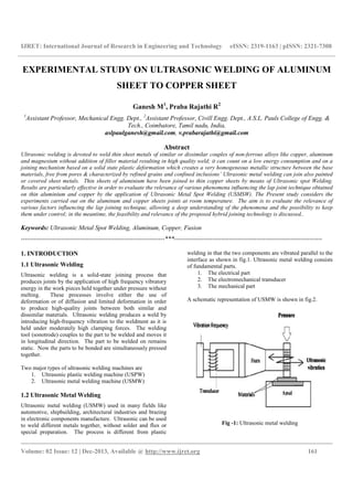
Fig -2: Schematic representation of USMW
1.3 Special characteristics of Ultrasonic Metal
Welding
1. Metals with widely different melting points can be
welded
2. Thin foils or wires can be welded too much thicker
parts
3. Temperature in the weld area is below the melting
point of the welded material
4. No fluxes or protective gas are needed.
1.4 Advantages of USMW
1. Surface preparation is not critical
2. No defects are produced from gases and filler
materials
3. Dissimilar metals having vastly different melting
points can be joined
4. Minimum surface deformation results
5. Very thin materials can be welded
6. Thin and thick sections can be joined together
7. To weld glass is impossible by any other means
8. The equipment is simple and reliable and only
moderate skill is required of the operator
1.5 Disadvantages of USMW
1. Ultrasonic welding is not economically competitive
when other processes can be used to do the same job
2. This process is restricted to joining thin materials
sheet, foil and wire. The maximum is about 3mm for
aluminum and 1mm for the harder metals.
3. Materials being welded tend to weld to the tip and
anvil
4. Due to fatigue loading, the life of equipment is short
5. Hard materials will fatigue under the stresses
necessary for welding
6. Very ductile materials will yield under ultrasonic
strain without sliding.
2. INTRODUCTION TO TAGUCHI METHOD
Dr. Taguchi of Nippon Telephones & Telegraph Company,
Japan has developed a method based on “ORTHOGONAL
ARRAY” experiments which gives much reduced “variance”
for the experiment with “optimum setting” of control
parameters. Orthogonal Arrays (OA) provide a set of well
balanced (minimum) experiments and Dr. Taguchi’s signal to
noise ratios (S/N), which are log functions of desired output,
serve as objective functions for optimization, help in data
analysis and prediction of optimum results.
2.1 Eight steps in Taguchi Methodology
1. Identify the main function, side effects and failure
mode
2. Identify the noise factors, testing conditions and
quality characteristics
3. Identify the objective function to be optimized
4. Identify the control factors and their levels
5. Select the orthogonal array matrix experiment
6. Conduct the matrix experiment
7. Analyze the data, predict the optimum levels and
performance
8. Perform the verification experiment and plan the
future action
Table -1: Orthogonal array
Experiment
No.
Column
1
Column
2
Column
3
Column
4
1 1 1 1 1
2 1 2 2 2
3 1 3 3 3
4 2 1 2 3
5 2 2 3 1
6 2 3 1 2
7 3 1 3 2
8 3 2 1 3
9 3 3 2 1
3. METHODOLOGY
3.1 Methodology for Experimental Work
1. Selection of specimen – specimen is characterized by
a length of 100mm; a width of 25mm and thickness
of 0.2mm aluminium [GRADE 8011] have been
joined with an overlap of 6mm. The weld specimens
are prepared according to ASTM standards (D1002-
01)](data:image/gif;base64,R0lGODlhAQABAIAAAAAAAP///yH5BAEAAAAALAAAAAABAAEAAAIBRAA7)
Recommended
Recommended
More Related Content
What's hot
What's hot (19)
Viewers also liked
Viewers also liked (20)
Similar to Ultrasonic Welding of Aluminum and Copper Sheets
Similar to Ultrasonic Welding of Aluminum and Copper Sheets (20)
More from eSAT Publishing House
More from eSAT Publishing House (20)
Recently uploaded
Recently uploaded (20)
Ultrasonic Welding of Aluminum and Copper Sheets
- 1. IJRET: International Journal of Research in Engineering and Technology eISSN: 2319-1163 | pISSN: 2321-7308 __________________________________________________________________________________________ Volume: 02 Issue: 12 | Dec-2013, Available @ http://www.ijret.org 161 EXPERIMENTAL STUDY ON ULTRASONIC WELDING OF ALUMINUM SHEET TO COPPER SHEET Ganesh M1 , Praba Rajathi R2 1 Assistant Professor, Mechanical Engg. Dept., 2 Assistant Professor, Civill Engg. Dept., A.S.L. Pauls College of Engg. & Tech., Coimbatore, Tamil nadu, India, aslpaulganesh@gmail.com, v.prabarajathi@gmail.com Abstract Ultrasonic welding is devoted to weld thin sheet metals of similar or dissimilar couples of non-ferrous alloys like copper, aluminum and magnesium without addition of filler material resulting in high quality weld; it can count on a low energy consumption and on a joining mechanism based on a solid state plastic deformation which creates a very homogeneous metallic structure between the base materials, free from pores & characterized by refined grains and confined inclusions’ Ultrasonic metal welding can join also painted or covered sheet metals. Thin sheets of aluminium have been joined to thin copper sheets by means of Ultrasonic spot Welding. Results are particularly effective in order to evaluate the relevance of various phenomena influencing the lap joint technique obtained on thin aluminium and copper by the application of Ultrasonic Metal Spot Welding (USMSW). The Present study considers the experiments carried out on the aluminum and copper sheets joints at room temperature. The aim is to evaluate the relevance of various factors influencing the lap joining technique, allowing a deep understanding of the phenomena and the possibility to keep them under control; in the meantime, the feasibility and relevance of the proposed hybrid joining technology is discussed.. Keywords: Ultrasonic Metal Spot Welding, Aluminum, Copper, Fusion --------------------------------------------------------------------***---------------------------------------------------------------------- 1. INTRODUCTION 1.1 Ultrasonic Welding Ultrasonic welding is a solid-state joining process that produces joints by the application of high frequency vibratory energy in the work pieces held together under pressure without melting. These processes involve either the use of deformation or of diffusion and limited deformation in order to produce high-quality joints between both similar and dissimilar materials. Ultrasonic welding produces a weld by introducing high-frequency vibration to the weldment as it is held under moderately high clamping forces. The welding tool (sonotrode) couples to the part to be welded and moves it in longitudinal direction. The part to be welded on remains static. Now the parts to be bonded are simultaneously pressed together. Two major types of ultrasonic welding machines are 1. Ultrasonic plastic welding machine (USPW) 2. Ultrasonic metal welding machine (USMW) 1.2 Ultrasonic Metal Welding Ultrasonic metal welding (USMW) used in many fields like automotive, shipbuilding, architectural industries and brazing in electronic components manufacture. Ultrasonic can be used to weld different metals together, without solder and flux or special preparation. The process is different from plastic welding in that the two components are vibrated parallel to the interface as shown in fig.1. Ultrasonic metal welding consists of fundamental parts. 1. The electrical part 2. The electromechanical transducer 3. The mechanical part A schematic representation of USMW is shown in fig.2. Fig -1: Ultrasonic metal welding
- 2. IJRET: International Journal of Research in Engineering and Technology eISSN: 2319-1163 | pISSN: 2321-7308 __________________________________________________________________________________________ Volume: 02 Issue: 12 | Dec-2013, Available @ http://www.ijret.org 162 Fig -2: Schematic representation of USMW 1.3 Special characteristics of Ultrasonic Metal Welding 1. Metals with widely different melting points can be welded 2. Thin foils or wires can be welded too much thicker parts 3. Temperature in the weld area is below the melting point of the welded material 4. No fluxes or protective gas are needed. 1.4 Advantages of USMW 1. Surface preparation is not critical 2. No defects are produced from gases and filler materials 3. Dissimilar metals having vastly different melting points can be joined 4. Minimum surface deformation results 5. Very thin materials can be welded 6. Thin and thick sections can be joined together 7. To weld glass is impossible by any other means 8. The equipment is simple and reliable and only moderate skill is required of the operator 1.5 Disadvantages of USMW 1. Ultrasonic welding is not economically competitive when other processes can be used to do the same job 2. This process is restricted to joining thin materials sheet, foil and wire. The maximum is about 3mm for aluminum and 1mm for the harder metals. 3. Materials being welded tend to weld to the tip and anvil 4. Due to fatigue loading, the life of equipment is short 5. Hard materials will fatigue under the stresses necessary for welding 6. Very ductile materials will yield under ultrasonic strain without sliding. 2. INTRODUCTION TO TAGUCHI METHOD Dr. Taguchi of Nippon Telephones & Telegraph Company, Japan has developed a method based on “ORTHOGONAL ARRAY” experiments which gives much reduced “variance” for the experiment with “optimum setting” of control parameters. Orthogonal Arrays (OA) provide a set of well balanced (minimum) experiments and Dr. Taguchi’s signal to noise ratios (S/N), which are log functions of desired output, serve as objective functions for optimization, help in data analysis and prediction of optimum results. 2.1 Eight steps in Taguchi Methodology 1. Identify the main function, side effects and failure mode 2. Identify the noise factors, testing conditions and quality characteristics 3. Identify the objective function to be optimized 4. Identify the control factors and their levels 5. Select the orthogonal array matrix experiment 6. Conduct the matrix experiment 7. Analyze the data, predict the optimum levels and performance 8. Perform the verification experiment and plan the future action Table -1: Orthogonal array Experiment No. Column 1 Column 2 Column 3 Column 4 1 1 1 1 1 2 1 2 2 2 3 1 3 3 3 4 2 1 2 3 5 2 2 3 1 6 2 3 1 2 7 3 1 3 2 8 3 2 1 3 9 3 3 2 1 3. METHODOLOGY 3.1 Methodology for Experimental Work 1. Selection of specimen – specimen is characterized by a length of 100mm; a width of 25mm and thickness of 0.2mm aluminium [GRADE 8011] have been joined with an overlap of 6mm. The weld specimens are prepared according to ASTM standards (D1002- 01)
- 3. IJRET: International Journal of Research in Engineering and Technology eISSN: 2319-1163 | pISSN: 2321-7308 __________________________________________________________________________________________ Volume: 02 Issue: 12 | Dec-2013, Available @ http://www.ijret.org 163 2. Selection of Optimum parameters for joining the specimen 3.2 Methodology for Analysis Work in Laboratory 1. Tensile shear strength comparisons done on the following specimens: 1. Ultrasonic welded samples of Aluminium and copper sheets at room temperature 2. Tensile strength testing on the specimen samples 3. 18 samples each tested for tensile shear strength 4. EXPERIMENTAL WORK 4.1 Introduction In this work, aluminium sheet material specimen of 0.2mm (Grade 8011) and copper sheet of 2mm has been selected. The experimental setup for the Ultrasonic metal welding is shown in fig.3. In this experimental work horn made up of hardened steel with diamond knurl pattern and steel anvil with diamond knurled pattern is used for avoid slip between the work pieces. Fig -3: Ultrasonic metal welding matching setup 4.2 USMW Machine Specification Make: Metal weld 2500, National Indosonic, Pune Input power: 230V, 50Hz single phase Output power: 2500 W Output frequency: 20 KHz Max. Amplitude: 60 μm Max pressure: 8 bar Stroke length: 25mm 4.3 Testing Procedures Ultrasonic welding parameters applied to the experimentation reported in the present paper have been indicated below: 1. Welding tip size - 5 x 5 mm 2. Vibration amplitude - 28μm, 42.5μm, 57μm 3. Pressure - 3.5 bar, 4 bar, 4.5 bar 4. Delay time - 4 sec 5. Weld time - 3.5 sec, 4 sec, 4.5sec 6. Hold time - 4 sec Ultrasonic metal welding is carried out for the following combination of sample: 1. Ultrasonic welding samples with aluminium sheets of 2mm and copper sheets of 2mm at room temperature. 2. Shear strength tested on the aluminium and copper samples. 18 samples are tested for tensile shear strength. Strength of the joints is measured using computerized tensile testing machine. Strength of weld at the weld interface is a direct indicator of the quality of joints. So, in order to find out the weld strength at the interface computerized tensile testing machine as shown in fig.4. It consists of load cells (10KN and 200N), gripper for flat specimen (0-10mm thickness) and electronic control panel. Fig -4: Tensile testing machine (UTM) 4.4 UTM Specifications: Model: TKG – EC – 10KN Maximum capacity : 10KN Least count displacement : 0.1mm Accuracy of load : 1% of indicated load from 4% to 100 of load cell capacity Grip separation : 25 – 750mm
- 4. IJRET: International Journal of Research in Engineering and Technology eISSN: 2319-1163 | pISSN: 2321-7308 __________________________________________________________________________________________ Volume: 02 Issue: 12 | Dec-2013, Available @ http://www.ijret.org 164 Straining rate : 1mm / min to 100 mm/min Power : single phase 220V 50Hz AC Motor : 0.5Hp 4.5 Specimen Preparation Before the process is carried out samples were cleaned with acetone to remove the surface impurity as it may affect the bond strength. Fig. 5 shows the standard size of specimen from ASTM standard (D 1002 -01). A universal testing machine was used to determine the weld strengths. 0.2mm Fig -5: Prepared specimens as per ASTM standards (D1002 - 01) 5. RESULTS Tensile shear strength results obtained for the tested joints are given below: Table -2: tensile shear strength Pressure (bar) Weld time (sec) Amplitude (μ) weight (N) S/N ratio 3.5 3.5 28 26.5 28.46 3.5 4 42.5 13 22.27 3.5 4.5 57 80.5 38.12 4 3.5 42.5 52.5 34.4 4 4 57 36 31.13 4 4.5 28 10 20.0 4.5 3.5 57 57.5 35.19 4.5 4 28 63 35.98 4.5 4.5 42.5 67 36.52 Fig -6: Samples with cured adhesive & without Ultrasonic Welding Fig -7: Samples with uncured adhesive and ultrasonically welded Fig -8: Samples- No adhesive, Ultrasonic welded.
- 5. IJRET: International Journal of Research in Engineering and Technology __________________________________________________________________________________________ Volume: 02 Issue: 12 | Dec-2013, Available @ Fig -9: Samples – Ultrasonic welded with cured adhesive Fig -10: Aluminium test specimen Fig -11: Graph plotted for tensile test report IJRET: International Journal of Research in Engineering and Technology eISSN: 2319 __________________________________________________________________________________________ 2013, Available @ http://www.ijret.org Ultrasonic welded with cured adhesive specimen tensile test report Fig -12: Graph plotted for Mean of Means Fig -13: Graph plotted for S/N ratios Fig -14: minitab software results (tensile test report) eISSN: 2319-1163 | pISSN: 2321-7308 __________________________________________________________________________________________ 165 : Graph plotted for Mean of Means : Graph plotted for S/N ratios : minitab software results (tensile test report)
- 6. IJRET: International Journal of Research in Engineering and Technology eISSN: 2319-1163 | pISSN: 2321-7308 __________________________________________________________________________________________ Volume: 02 Issue: 12 | Dec-2013, Available @ http://www.ijret.org 166 CONCLUSIONS This study is focused on the dissimilar metal sheets (Aluminium thin sheets and copper thin sheets) joining technique based on Ultrasonic welding. Main results are: • When ultrasonic welding done on a specimen in three different parameters, the weld time and amplitude is playing vital role in weld strength. When amplitude is low with high weld time and moderate pressure, weld strength is poor. • When pressure is low high amplitude and high weld time, the weld strength is good. When the amplitude is high, the weld strength also is high. REFERENCES [1]. “Performance Variability of Aluminium Hybrid Lap Joints obtained by means of Adhesives and Ultrasonic Welding” by M. Annoni, F. Moroni, V. Mussi (Dept. Of Industrial Engg., Italy) published in Springer in the year 2010. [2]. “Tensile shear fatigue behaviour of aluminium and Magnesium lap joint obtained by ultrasonic welding and adhesive bonding” published by Michaele Carboni, Fabrizia Moroni (dept. Of Industrial Engg, Italy) in Science Direct. [3]. “Ultrasonic welding of Hybrid joints by Guntram Wagner, Frank Balle” (University of Kaiserslautern, Germany) journal published online in March 2012. [4]. “Ultrasonic welding and simulation of flow at the interface” by Levi, Le Corre, Poitu published in Springer in 2010. [5]. “Implémentation of ultrasonic metal welding on an aluminium vehicle structure” – a paper presented in UIA meeting in March 2007 by Susan Ward, Daniel Wilkosz, Ray Johm. [6]. Technical data sheet RESINOVA BONDTITE® [7]. ASM Hand Book, 2000, “Welding, Brazing, Soldering”, Vol. 6, ASM International. [8]. “Ultrasonic Welding of aluminium sheet”, Janet Devine and Joe Walsh, presented in Ford company. [9] “Mini tab software version- release 15. BIOGRAPHIES He is now working as an assistant professor of mechanical Engg. Dept., A.S.L. pauls college of engg. & Tech. He finished his B.E.(mech) in Government college of technology, Coimbatore and doing his M.E.(production engg.) in P.S.G. college of technology, Coimbatore. She is now working as an assistant professor of Civil Engg. Dept. in A.S.L. Pauls college of Engg. & Tech., Coimbatore. She completed her B.E.(civil) in Thiagarajar college of Engg., Madurai & completed her M.E.(environmental engg.) in Government college of technology, Coimbatore. Tamilnadu. India.