SlideShare a Scribd company logo
1 of 8
Download to read offline
Mr. C. Pavankumar et al Int. Journal of Engineering Research and Application
ISSN : 2248-9622, Vol. 3, Issue 5, Sep-Oct 2013, pp.1406-1413

RESEARCH ARTICLE

www.ijera.com

OPEN ACCESS

Single-Stage Inverter cum Chopper (Ssicc) For Pv-Battery
System
Mr. C. Pavankumar, Mr. C. Sudhakar, Mr. Kantae Visweswara
Kuppam Engineering College, Department Of Eee.

Abstract
This paper introduces a single stage inverter cum chopper (SSICC). This SSICC finds wide applications in grid
connected solar system since it uses single stage conversion instead of multistage conversion, reduced losses,
low cost, simple in construction, improved efficiency and reduced volume .The main concept of the SSIC is to
prefer single stage power converter on behalf of multistage converter for dc/ac and dc/dc operation for solar
energy storage applications.

Index Terms— Photovoltaic (PV) system, Maximum power point tracking, Power Converter, energy storage
system.

I.

INTRODUCTION

The output of solar system is not a
continuous process it is time dependent & intermittent
energy resource .It depends on the insolation, time of
the day, direction of sunlight and the weather
conditions. The output of solar system falls
dramatically when a portion of solar panel gets
covered. Due to stability point of view an energy
source that can be that can deliver power at the
request are desired. As a result, energy storage such as
batteries should be connected to solar systems to
improve the performance of solar systems. There are
different techniques for connecting energy storage to
solar system. The techniques used till now for power
conversion may consist of increased conversion
stages. Every techniques has its merits and demerits
.Therefore every technique should be distinguished
with regard to the conversion stages, efficiency, cost,
construction & circuit complexity, etc.
This paper initiates an SSICC. SSICC
perform different operation such as DC-DC &DC-AC
.Part II introduces the proposed SSICC, operating
modes, and system benefits. In Part III, operation of
the proposed technique, refinement to previous
techniques are discussed. Part IV verifies the
proposed system with the help of simulation &
MATLAB
to
evaluate
the
performance
characteristics. Part V summarizes and concludes the
paper.
www.ijera.com

II.

PROPOSED SSICC

A. Introduction

Fig. 2. Diagram of the proposed SSICC circuit.
The SSICC is basically a three-phase PV
inverter. Fig. 2 shows the diagrammatic view of
SSICC. The SSICC provides changes to the
conventional three-phase inverter system. These
changes allow the proposed system to utilize the
conventional three-phase inverter system to operate as
both chopper & inverter for integration of solar
energy system with the batteries. The SSICC is a
three-phase voltage source converter and its
associated components, the proposed system requires
1406 | P a g e
Mr. C. Pavankumar et al Int. Journal of Engineering Research and Application
ISSN : 2248-9622, Vol. 3, Issue 5, Sep-Oct 2013, pp.1406-1413
optional inductors in addition to ac filter inductance
B. Switching states of the proposed system
The five possible operation modes for the
proposed system are as fallows.
(a) Mode 1—PV to grid (S1 and S6 switches
remain open)
(b)Mode 2—PV to battery (switch S6 close & S5, S3
open)
(c) Mode 3—PV/battery to grid (switch S6 open &
S1, S2, S3, S4 & S5 close)
(d) Mode 4—battery to grid (switch S1, S2, S3 & S5
close & S4, S6 open)
(a)In Mode 1, the solar panels are directly connected
to the grid with maximum power point tracking
(MPPT) by a dc/ac operation of the SSICC.

www.ijera.com

suppose is not enough for the charging purpose.
strong asset which helps them to plan and operate
the power plant with respect to their needs. The
SSICC has reduced conversion stages, high
efficiency, low cost & simple in design etc.

Fig. 3. Solar energy storage systems with the
SSICC and the state-of-the-art solution
(b)In Mode 2, the solar panels charge the batteries
through dc/dc operation of the converter. In this
mode it is possible to track maximum power with the
help of MPPT algorithm.

D. SYSTEM CONTROL SCHEMES
In response to the request of the grid
operator, different system control techniques can be
realized with the SSICC solar power plants & are as
follows:
1)system control 1 for Pgen > Preq ;
2)system control 2 for Pgen < Preq ;
3)system control 3 for Pgen = Preq ;
4) system control 3 for Pgen = 0;

(c)In Mode 3 both the solar panels & batteries are
connected to the grid by closing the switch S1.

(d)Mode 4 delivers the energy stored in the battery to
the grid.
Fig. 5. System control schemes

III.

C. Advantages of SSICC
The SSICC provides significant merits to
solar power plants. The current state-of-the-art
technology is to integrate the energy storage into the
ac side of the solar system. It can be utilized as a
mean for shifting peak hours to solar power plants.
This technique allows the system owners to have a
www.ijera.com

SINGLE STAGE CONVERTER
CONTROL

A. Control of the proposed system in DC/AC
operation modes (modes 1, 3 &4)
The dc/ac operation of the SSICC is utilized
for delivering power from PV to grid, battery to grid,
PV and battery to grid, and grid to battery. The single
stage converter performs the MPPT algorithm to
deliver maximum power from the PV to the grid.
Like the conventional solar inverter control, the
SSICC is implemented in the synchronous reference
frame.
The
synchronous
reference
frame
1407 | P a g e
Mr. C. Pavankumar et al Int. Journal of Engineering Research and Application
ISSN : 2248-9622, Vol. 3, Issue 5, Sep-Oct 2013, pp.1406-1413
proportional-integral current control is employed. In
a reference frame rotating synchronously with the 2.
fundamental excitation, the fundamental excitation
signals are transformed into dc signals. As a result,
the current regulator forming the innermost loop of
the control system is able to regulate ac cur-rents
over a wide frequency range with high bandwidth
and zero steady-state error. For the pulse width
modulation (PWM) scheme, the conventional space
vector PWM scheme is utilized. Fig. 6 presents the
overall control block diagram of the single stage
converter in the dc/ac operation. For the dc/ac
operation with the battery, the proposed system
control should be coordinated with the battery
management system (BMS), which is not shown in
Fig. 6.
B. Control of the proposed system in DC/DC
operation modes (modes 2)
The dc/dc operation of the single stage
converter is also utilized for delivering the maximum
power from the solar panels to the battery. The
SSICC in the dc/dc operation is a boost converter
which controls the current flowing into the battery.
In this paper, Li-ion battery has been selected for the
solar energy storage systems due to its advantages.
Li-ion batteries are charged in two stages

www.ijera.com

1. CC
CV
CC: Applying constant charging current to the
battery, until the voltage limit per cell is reached.
CV: Apply a constant voltage equal to the maximum
cell voltage with respect to the number of cells in
series with the battery, as the current gradually falls
to chase 0, until the current is less than a set
threshold value of about 3% of initial constant
charging current.
Thus, the dc/dc converter used in charging
process must be capable of giving stable control for
maintaining either current or voltage at a constant
value, depending on the status of the battery.
Normally certain capacity losses occur if constant
voltage charging is not preferred. However, it is not
necessary to avoid constant current charging to
simplify the charging control and process. The latter
technique can be used to charge batteries, from the
control point of view, it is just enough to control only
the inductor current. Therefore for charging the Liion batteries the SSICC performs the MPPT
algorithm to deliver maximum power from the solar
panel to the battery in the dc/dc operation. Fig. 7
shows the overall control circuit of the single stage
converter in the dc/dc operation.

Fig. 5. Overall control block diagram of the proposed circuit in dc/ac operation.

Fig. 7. Overall control block diagram of the proposed circuit for dc/dc operation.
C. Design considerations and modifications to
conventional three phase inverter for solar battery
system:
One of the most important requirements of
the paper is that the proposed solution must have
minimal complexity and modifications to the
conventional three-phase solar converter system.
www.ijera.com

Therefore, it is necessary to investigate how a threephase dc/ac converter operates as a dc/dc converter
and what modifications should be made. It is common
to use a LCL filter for a high-power three-phase PV
converter .Therefore the SSICC in the dc/dc operation
is expected to use the inductors already available in
the LCL filter. There are basically two types of
1408 | P a g e
Mr. C. Pavankumar et al Int. Journal of Engineering Research and Application
ISSN : 2248-9622, Vol. 3, Issue 5, Sep-Oct 2013, pp.1406-1413
inductors, coupled three-phase inductor and three
single-phase inductors that can be utilized in the
single stage converter circuit.

TABLE I
INDUCTANCE VALUE OF A COUPLED THREEPHASE INDUCTOR IN THE DC/DC OPERATION
Using all three phases of the coupled threephase inductor in the dc/dc operation causes a
significant drop in the inductance
value due to
inductor core saturation. Table I presents an example
of inductance value of a coupled three-phase inductor
for the dc/dc operation, which shows significant drop
in the inductance value. The reduction in inductance
value requires inserting additional inductors for the
dc/dc operation which has been marked as “optional”
in Fig. 2. To avoid extra inductors, only one phase can
perform the–dc/dc operation. However, when only
one phase, for instance phase B, is utilized for the
dc/dc operation with only either upper or lower three
insulated-gate bipolar transistors (IGBTs) are turned
OFF as complementary switching, the circulating
current occurs in phases A and C through filter
capacitors, the coupled inductor, and switches,
resulting in significantly high current ripple in phase
B current, as shown in Fig. 8.
To prevent the circulating current in the dc/dc
operation, the following two solutions are proposed;
1) All unused upper and lower IGBTs must be turned
OFF;
2) The coupled inductor is replaced by three singlephase Inductors.
While the first solution with a coupled inductor is
straight-forward, using three single-phase inductors

www.ijera.com

makes it possible to use all three phase legs for the
dc/dc operation. There are two methods to utilize all
three phase legs for the dc/dc operation:
1) Synchronous operation;
2) Interleaving operation.
In the first solution, all three phase legs can
operate synchronously with their own current control.
In this case, the battery can be charged with a higher
current compared to the case with one-phase dc/dc
operation. This leads to a faster charging time due to
higher charging current capability. However, each
phase operates with higher current ripples. Higher
ripple current flowing into the battery and capacitor
can have negative effects on the lifetime of the battery
and capacitors.
To overcome the aforementioned problem
associated with the synchronous operation, phases B
and C can be shifted by applying a phase offset. For
the interleaving operation using three phase legs,
phases B and C are shifted by 120◦ and 240◦,
respectively. The inductor current control in
interleaving operation re requires a different inductor
current sampling scheme, as shown in Fig. 9. However, for three-phase interleaving, a modified
sampling scheme is required to measure the average
currents for all three phases. Therefore, the sampling
points for phases B and C must be shifted by 120 ◦ and
240◦, respectively [see Fig 9(b)], which may imply
that computation required inductor current control for
each phase should be done asynchronously. Using the
interleaving operation reduces the ripples on the
charging current flowing into the battery. Therefore,
the filter capacitance value can be reduced
significantly.
D. Mode Change Control
The basic concept of the SSICC is to use a
single power electronics circuit to perform different
operation modes such as PV to grid (dc to ac) and PV
to battery (dc to dc) for PV systems with energy
storage, as discussed earlier. Therefore, in addition to
the converter control in each mode, the seamless
transition between modes is also essential for the
single stage converter operation. To change a mode,
the single stage converter must be reconfigured by
either disconnecting or connecting components such
as the battery through contactors.

Fig. 8. Circulating current path if one phase is used for the dc/dc operation of the proposed circuit with
a coupled three-phase inductor.

www.ijera.com

1409 | P a g e
Mr. C. Pavankumar et al Int. Journal of Engineering Research and Application
ISSN : 2248-9622, Vol. 3, Issue 5, Sep-Oct 2013, pp.1406-1413

www.ijera.com

Fig. 9. Inductor current sampling schemes in the interleaving operation.
(a) Two-phase interleaving. (b) Three-phase interleaving.
It is very important to understand the
dynamics of the SSICC. Generally, it is necessary to
understand the relay response time such as how
much time it takes for a relay to completely close or
open. Hence, the performance curves of all re-lays
used in the SSICC circuit must be investigated. All
relays used in the SSICC circuit have a maximum
operating time equal to or smaller than 50 ms. All
switching, which occur during mode change, are
done under zero or nearly zero current, except fault
cases. To verify the operating time given in the
datasheet of the relays, a test for one of the relays
used is made. The operating time of the relay used
for SChgDC in Fig. 8 is investigated during pre
charging of the inverter capacitors. The captured
waveforms are shown in Fig. 10.The relay signal
inside the DSP is captured through a D/A converter.
It takes 240 μs until the signal reaches a value, 12 V,
that is high enough to trigger the relay switching.
Once the operating voltage is applied to the relay, it
takes 20 ms until the current starts flowing through
the relay. In other words, it takes 20 ms for the relay
to be fully closed. The measured relay operating time
of 20 ms is only half of the value given in the
datasheet. For all relays used in the circuit, 80 ms is
used as the relay switching transient time for both
closing and releasing.

The highest layer of the RSC mode change
control is shown in Fig. 11. This layer consists of
fault detection, fault reset, and normal operation. The
basic fault detection such as detecting over current
and overvoltage and fault management like turning
off PWM signals are implemented inside the
converter control executed in the inner most control
loop. In this way, fast fault detection and protection
are possible.

www.ijera.com

In general, shutting down all PWM signals
is able to clear the fault. In addition, all relays are
forced to be opened. If the system is operating
normal, the status of the system will be “Normal
Condition.” Once the fault flag is set by detecting a
fault, the status of the system will be changed to
“Fault Condition.” In this status, all relays as well as
PWM signals are turned off. When the system is in
“Fault Condition,” the single stage converter control
tries to clear a fault condition every 1 s. If a fault
cannot be cleared, the system will remain in the
“Fault Condition.” If a fault is cleared, “Normal
Condition” will be reinstated. Inside “Normal
Condition,” the system always starts with Mode 0,
which is the shutdown mode. This allows the single
stage converter to move to a new mode safely, after a
fault is cleared.

Fig. 12. States inside “Normal Condition.”
The control topology inside “Normal
Condition” is presented in Fig. 12. The single stage
converter control mode can be changed to any mode
from the present mode. If Modes 1 or 2 are
commanded, the state will change from “Mode 0” to
“PVCharge1” and relay “SChgDC” will be closed.
This will charge the capacitor “Cdc ” through the
resistor “RChgDC.” Once the dc voltage of the
capacitor reaches 98% of the source voltage, the state
1410 | P a g e
Mr. C. Pavankumar et al Int. Journal of Engineering Research and Application
ISSN : 2248-9622, Vol. 3, Issue 5, Sep-Oct 2013, pp.1406-1413
will change to “PVCharge2.”
This will also close relay “SPV,” while the
re-lay “SChgDC” will remain closed, because no
new action refers to this relay. To make sure that the
relay “SPV” is fully closed, a delay of 80 ms, relay
switching transient time, is used, as discussed earlier.
For example, the procedure of Mode 1 is described.
Let us assume that the current state is “Mode1pre.”
The relay “SChgDC” is opened, so that the pre
charging procedure is completed. Also, the three
grid-switches “Sag,” “Sbg,” and “Scg” are closed
and therefore the load is connected to the single stage
converter. Furthermore, the relay “SChg” is opened
and the control is set to Mode 1, which is dc/ac
control. Because relay switching is included in the
state “Mode1pre,” a delay of 80 ms is required to
move to the state of “Run Circuit.” When the
previous mode is 1, it is possible to directly move to
“Mode2pre.”
This would bypass the pre charging process
since the capacitors of the inverter are required to be
connected to the PV side in both modes. All the
actions from “Mode2pre” shown in Fig. 12 are
executed. After 80 ms, the state moves to “Run
Circuit” shown in Fig. 13. When the previous mode
is Mode 2 and the new mode is Mode 1, the state
directly moves from “PWMOFF” to “Mode1pre” and
back to “Run Circuit” by avoiding the pre charge
process.

The startup of Mode 4 is different from
Modes 1 and 2, be-cause it connects the battery to
the inverter instead of connecting the PV to it. But
the pre charging procedure is quite the same. Only
different relays are used—“STran” for charging the
capacitor “Cdc ” through the resistance “RTran” and
relay “SBat” for directly connecting the battery to the
inverter. Then, the state “Mode4pre” closes the grid
switches and sets the mode control to number 4,
which is again dc/ac control.
After “Mode4pre,” the state changes to “Run
Circuit.” Going from Modes 1 or 2 to Mode 4 or vice
versa is not as easy as the mode change between
Modes 1 and 2. The dc voltage always has to be
changed to either the battery voltage (coming from
Mode 1 or 2) or the PV voltage (coming from Mode
4), which makes the mode change control to use
Mode 0 for transition. This does not mean that the
circuit needs to be fully de energized, since the pre
charging resistances limit the current and can
therefore take care of this process.

www.ijera.com

www.ijera.com

IV.
PERFORMANCE
CHARECTERISTICS OF SSICC
The proposed system control algorithms are
verified with the help of MATLAB/Simulink. The
performance of the SSICC in different operation
modes has been tested with the help of
MATLAB/Simulink to analyze the performance of
SSICC.
A. Simulation results of the proposed system in
DC/AC Operation Modes

(a)

(b)

(c)
Steady-state performance operating modes for
the proposed system in DC /AC. (a) Mode 1—PV
to grid (b) Mode 3—PV/battery to grid. (c)
Mode 4—battery to grid.
The above figure shows the steady-state
performance of dc/ac control in Mode 1. In this test,
the voltage on the dc side VD C of the inverter is set to
200 V. The current reference is set to 5 Ap eak for the
frequency of 60 Hz. Fig. a shows the steady-state
performance of dc/ac control in Mode 1.. In Fig. b,
shows the steady-state performance of dc/ac control
in Mode 3. The average battery charging current is
1.8 A. The battery charging current has about 0.85
Apk −pk current ripple with the frequency of 60 Hz.
C. Simulation results of the proposed system in
DC/DC Operation Mode

1411 | P a g e
Mr. C. Pavankumar et al Int. Journal of Engineering Research and Application
ISSN : 2248-9622, Vol. 3, Issue 5, Sep-Oct 2013, pp.1406-1413

(a)
Steady-state performance operating modes for
the proposed system in DC /DC. (a) Mode 2—PV
to Battery.
In Mode 2 (PV to battery), the three-phase
inverter is used as a dc/dc converter. As explained,
initially a coupled three-phase inductor is used for
the filter inductor to the inverter side. When only
phase B is utilized for the dc/dc operation with only
either upper or lower three IGBTs are turned off as
complementary switching, the circulating current
occurs in phases A and C through filter capacitors,
the coupled inductor, and switches, resulting in
significantly high current ripple in phase B current,
as shown in Fig. 18(a). To solve the aforementioned
problem, as explained, two solutions are proposed.
First, the switches un-used are turned off and
consequently the phase current presents much lower
ripple as shown in Fig. (b). The average current in
phase B is now 5 A with a ripple of 5 Apk −pk while
the current in phases A and C remains zero. This
means no circulating current. The second solution is
to use three single-phase inductors in the SSICC
circuit. As expected with single-phase operation in
this mode, the circulating current is vanished
automatically. The result of the test is presented in
Fig. (c) Show that the current in the other phases
remains zero while the battery is charged.
The average phase B current is 5 A and the
average battery current is also 5 A. The phase B
ripple is 5 Apk −pk and the battery current ripple is 1.4
Apk −pk . The capacitor ripple current is about 4.2 Apk
−pk .
Using three single-phase inductors enables the
SSICC to use all three phase legs in the dc/dc
operation. As discussed earlier, there are two
methods to utilize all three phase legs for the dc/dc
operation. In the first approach, all three phase-legs
operate synchronously with their own current
controls.
The sum of all three phase currents is 5 A,
which means that each phase carries one-third of it.
Therefore, it is possible to charge the battery with
even a higher current, which leads to a faster
charging time. However, each phase current shows
the current ripple of 5 Apk −pk · The battery current
has the current ripple of 4 Apk −pk and the capacitor
current shows the current ripple of 12 Apk −pk which
is almost three times as high as the ripple current of
the battery charging using a single phase leg. Higher
www.ijera.com

www.ijera.com

ripple current flowing into the battery and capacitor
can have negative effects on the lifetime of the
battery and capacitors.
As discussed earlier, using the interleaving operation
can reduce the ripples on the charging current
flowing into the battery. Battery current has a ripple
current of 0.5 Apk −pk and the capacitor current has a
ripple current of 1.5 Apk −pk when the sum of all three
phase currents is 5 A and the average battery current
is 5 A. These current ripples are one-third of the
ripple currents for dc/dc control using a single phase
leg and one-eighth of the ripple currents for dc/dc
control using all three phase legs in synchronous
operation, which means significant ripple reduction
is achieved by interleaving operation.

V.

CONCLUSION

This paper proposed a single stage inverter
cum chopper for solar- battery application,
particularly utility-scale solar-battery application for
solar applications. The proposed solution is also
suitable to other intermittent energy sources
including wind energy. The proposed solution
requires simple circuit complexity therefore; the
solution is very attractive for solar-battery
application, because it has reduced conversion
stages, improved efficiency and reduced cost,
weight, and volume.
The basic concept of the proposed system is to use a
single power conversion system instead of multistage
conversion system to integrate solar panels with
energy storage and grid.. Test results have been
presented to verify the concept of the proposed
system and to demonstrate the attractive performance
characteristics of the proposed system. These results
confirm that the proposed system is highly suitable
for intermittent energy storage systems.

REFERENCES
[1]

[2]

[3]

[4]

[5]

U.S. Department of Energy, “Solar energy
grid integration systems-energy storage
(SEGIS-ES),” May 2008.
D. Bundestag, “Gesetz zur Neuregelung des
Rechts der erneuerbaren Energienim
Strombereich und zur A¨ nderung
damitzusammenha¨ngenderVorschriften,”B
undesgesetzblatt, 2008.
H. Konishi, T. Iwato, and M. Kudou,
“Development of large-scale power
conditioning system in Hokuto mega-solar
project,” in Proc. Int. Power Electron.
Conf., 2010, pp. 1975–1979.
J. H. Enslin and D. B. Snyman, “Combined
low-cost, high efficient inverter,peak power
tracker and regulator for PV applications,”
IEEE Trans.Power Electron., vol. 6, no. 1,
pp. 73–82, Jan. 1991.
H. Ertl, J. W. Kolar, and F. Zach, “A novel
multicell dc-ac converter for applications in
renewable energy systems,” IEEE Trans.
1412 | P a g e
Mr. C. Pavankumar et al Int. Journal of Engineering Research and Application
ISSN : 2248-9622, Vol. 3, Issue 5, Sep-Oct 2013, pp.1406-1413

[6]

[7]

[8]

www.ijera.com

Ind. Electron.,vol. 49, no. 5, pp. 1048–1057,
Oct. 2002.
C. Zhao, S. D. Round, and J. W. Kolar, “An
isolated three-port bidirectional dc/dc
converter with decoupled power flow
management,”
IEEE
Trans.
Power
Electron., vol. 23, no. 5, pp. 2443–2453,
Sep. 2008.
M. Bragard, N. Soltau, R. W. De Doncker,
and
A.
Schiemgel,
“Design
and
implementation of a 5 kW photovoltaic
system with Li-ion battery and additional
dc/dc converter,” in Proc. IEEE Energy
Convers. Congr. Expo., 2010, pp. 2944–
2949.
W. Li, J. Xiao, Y. Zhao, and X. He, “PWM
plus phase angle shift control scheme for
combined multiport dc/dc converters, ”
IEEE Trans. Power Electron., vol. 27, no. 3,
pp. 1479–1489, Mar. 2012.

C.Pavankumar has obtained his B.Tech.
(Electrical and Electronics Engineering) from
kuppam engineering college, JNTUA University,
Anathapur in 2009. He is currently pursuing his
M.Tech. with specialization of Power Electronics
from kuppam engineering college, JNTU Anantapur.
His research area of interest includes Power
Electronics and Power Systems.

C.Sudhakar
has
obtained
his
B.Tech.(Electrical and Electronics Engineering) from
JNTUA University, Anathapur in 2009. He is
currently pursuing his M.Tech. (Power Electronics)
from JNTU Anantapur. His research area of interest
includes Power Electronics and Power Systems.

KANTE VISWESWARA has obtained his
B.Tech.(Electrical and Electronics Engineering) from
NARAYANA Engineering College, Nellore. in
2006. He completed M.Tech (Energy Systems) in
JNTU College Of Engineering, JNTUA, Anantapur
in the year 2008. Currently working as Assistant
Professor in Kuppam Engineering College in the
Department of EEE. His area of research is Energy
Auditing, Energy Conservation and Energy
Management.

www.ijera.com

1413 | P a g e

More Related Content

What's hot

A Integrated Technique of SIDO PFC Fly back Converter in power system
A Integrated Technique of SIDO PFC Fly back Converter in power systemA Integrated Technique of SIDO PFC Fly back Converter in power system
A Integrated Technique of SIDO PFC Fly back Converter in power systemIJMTST Journal
 
control-of-dcdc-converters-for-solar-energy-system-with-maximum-.pdf
control-of-dcdc-converters-for-solar-energy-system-with-maximum-.pdfcontrol-of-dcdc-converters-for-solar-energy-system-with-maximum-.pdf
control-of-dcdc-converters-for-solar-energy-system-with-maximum-.pdfDsriniva
 
Proposed PV Transformer-Less Inverter Topology Technique for Leakage Current ...
Proposed PV Transformer-Less Inverter Topology Technique for Leakage Current ...Proposed PV Transformer-Less Inverter Topology Technique for Leakage Current ...
Proposed PV Transformer-Less Inverter Topology Technique for Leakage Current ...IJPEDS-IAES
 
Power System Analysis unit - I
Power System Analysis unit - IPower System Analysis unit - I
Power System Analysis unit - Iarunatshare
 
MICROCONTROLLER BASED SOLAR POWER INVERTER
MICROCONTROLLER BASED SOLAR POWER INVERTERMICROCONTROLLER BASED SOLAR POWER INVERTER
MICROCONTROLLER BASED SOLAR POWER INVERTERIAEME Publication
 
Real Time Implementation of Variable Step Size Based P&O MPPT for PV Systems ...
Real Time Implementation of Variable Step Size Based P&O MPPT for PV Systems ...Real Time Implementation of Variable Step Size Based P&O MPPT for PV Systems ...
Real Time Implementation of Variable Step Size Based P&O MPPT for PV Systems ...IJPEDS-IAES
 
1 s2.0-s1364032117311978-main
1 s2.0-s1364032117311978-main1 s2.0-s1364032117311978-main
1 s2.0-s1364032117311978-mainAhmedAljabari
 
Design and Simulation of a Three Phase Power Converter Connected To a Distrib...
Design and Simulation of a Three Phase Power Converter Connected To a Distrib...Design and Simulation of a Three Phase Power Converter Connected To a Distrib...
Design and Simulation of a Three Phase Power Converter Connected To a Distrib...IJERA Editor
 
Analysis and design of grid connected photovoltaic systems
Analysis and design of grid connected photovoltaic systems Analysis and design of grid connected photovoltaic systems
Analysis and design of grid connected photovoltaic systems Karthik Dm
 
All ieee 2013
All ieee 2013All ieee 2013
All ieee 2013Ecwayt
 

What's hot (15)

K010418290
K010418290K010418290
K010418290
 
A Integrated Technique of SIDO PFC Fly back Converter in power system
A Integrated Technique of SIDO PFC Fly back Converter in power systemA Integrated Technique of SIDO PFC Fly back Converter in power system
A Integrated Technique of SIDO PFC Fly back Converter in power system
 
I010416376
I010416376I010416376
I010416376
 
control-of-dcdc-converters-for-solar-energy-system-with-maximum-.pdf
control-of-dcdc-converters-for-solar-energy-system-with-maximum-.pdfcontrol-of-dcdc-converters-for-solar-energy-system-with-maximum-.pdf
control-of-dcdc-converters-for-solar-energy-system-with-maximum-.pdf
 
Proposed PV Transformer-Less Inverter Topology Technique for Leakage Current ...
Proposed PV Transformer-Less Inverter Topology Technique for Leakage Current ...Proposed PV Transformer-Less Inverter Topology Technique for Leakage Current ...
Proposed PV Transformer-Less Inverter Topology Technique for Leakage Current ...
 
study of a DC-DC converter for solar LED street lighting
study of a DC-DC converter for solar LED street lightingstudy of a DC-DC converter for solar LED street lighting
study of a DC-DC converter for solar LED street lighting
 
Power System Analysis unit - I
Power System Analysis unit - IPower System Analysis unit - I
Power System Analysis unit - I
 
MICROCONTROLLER BASED SOLAR POWER INVERTER
MICROCONTROLLER BASED SOLAR POWER INVERTERMICROCONTROLLER BASED SOLAR POWER INVERTER
MICROCONTROLLER BASED SOLAR POWER INVERTER
 
Real Time Implementation of Variable Step Size Based P&O MPPT for PV Systems ...
Real Time Implementation of Variable Step Size Based P&O MPPT for PV Systems ...Real Time Implementation of Variable Step Size Based P&O MPPT for PV Systems ...
Real Time Implementation of Variable Step Size Based P&O MPPT for PV Systems ...
 
Fuzzy Logic based Maximum Power Point Tracker in Photovoltaic Cell
Fuzzy Logic based Maximum Power Point Tracker in Photovoltaic CellFuzzy Logic based Maximum Power Point Tracker in Photovoltaic Cell
Fuzzy Logic based Maximum Power Point Tracker in Photovoltaic Cell
 
1 s2.0-s1364032117311978-main
1 s2.0-s1364032117311978-main1 s2.0-s1364032117311978-main
1 s2.0-s1364032117311978-main
 
Design and Simulation of a Three Phase Power Converter Connected To a Distrib...
Design and Simulation of a Three Phase Power Converter Connected To a Distrib...Design and Simulation of a Three Phase Power Converter Connected To a Distrib...
Design and Simulation of a Three Phase Power Converter Connected To a Distrib...
 
IJET-V2I6P10
IJET-V2I6P10IJET-V2I6P10
IJET-V2I6P10
 
Analysis and design of grid connected photovoltaic systems
Analysis and design of grid connected photovoltaic systems Analysis and design of grid connected photovoltaic systems
Analysis and design of grid connected photovoltaic systems
 
All ieee 2013
All ieee 2013All ieee 2013
All ieee 2013
 

Viewers also liked

Viewers also liked (6)

Mining in the Municipality of Tampakan:Risks and Alternatives
Mining in the Municipality of Tampakan:Risks and AlternativesMining in the Municipality of Tampakan:Risks and Alternatives
Mining in the Municipality of Tampakan:Risks and Alternatives
 
Curso de c++
Curso de c++Curso de c++
Curso de c++
 
Info night wsup
Info night wsupInfo night wsup
Info night wsup
 
Clipping Dezembro 2
Clipping Dezembro 2Clipping Dezembro 2
Clipping Dezembro 2
 
Ps slides wk 2
Ps slides wk 2Ps slides wk 2
Ps slides wk 2
 
Trabajo de work 2010 walther
Trabajo de work 2010 waltherTrabajo de work 2010 walther
Trabajo de work 2010 walther
 

Similar to Ia3514061413

Analysis of Reconfigurable Solar Converter using MPPT Techniques
Analysis of Reconfigurable Solar Converter using MPPT TechniquesAnalysis of Reconfigurable Solar Converter using MPPT Techniques
Analysis of Reconfigurable Solar Converter using MPPT Techniquesijtsrd
 
Design and Simulation of MPPT Algorithm for Three Phase Induction Motor Solar...
Design and Simulation of MPPT Algorithm for Three Phase Induction Motor Solar...Design and Simulation of MPPT Algorithm for Three Phase Induction Motor Solar...
Design and Simulation of MPPT Algorithm for Three Phase Induction Motor Solar...ijtsrd
 
A Review on Methodologies of Multi Array PV Battery Based Bi- Directional Con...
A Review on Methodologies of Multi Array PV Battery Based Bi- Directional Con...A Review on Methodologies of Multi Array PV Battery Based Bi- Directional Con...
A Review on Methodologies of Multi Array PV Battery Based Bi- Directional Con...IRJET Journal
 
Design and Analysis of Three Phase Inverter with Two Buck/Boost MPPTs for DC ...
Design and Analysis of Three Phase Inverter with Two Buck/Boost MPPTs for DC ...Design and Analysis of Three Phase Inverter with Two Buck/Boost MPPTs for DC ...
Design and Analysis of Three Phase Inverter with Two Buck/Boost MPPTs for DC ...IJERA Editor
 
Maximum power point tracking of pv arrays under partial shading condition usi...
Maximum power point tracking of pv arrays under partial shading condition usi...Maximum power point tracking of pv arrays under partial shading condition usi...
Maximum power point tracking of pv arrays under partial shading condition usi...eSAT Publishing House
 
Power Flow Control for Dc Microgrid Using MPPT Technique
Power Flow Control for Dc Microgrid Using MPPT TechniquePower Flow Control for Dc Microgrid Using MPPT Technique
Power Flow Control for Dc Microgrid Using MPPT TechniqueIRJET Journal
 
IRJET- A Review on Solar based Multilevel Inverter with Three Phase Grid Supply
IRJET- A Review on Solar based Multilevel Inverter with Three Phase Grid SupplyIRJET- A Review on Solar based Multilevel Inverter with Three Phase Grid Supply
IRJET- A Review on Solar based Multilevel Inverter with Three Phase Grid SupplyIRJET Journal
 
IRJET-Robot Control by using Human Hand Gestures
IRJET-Robot Control by using Human Hand GesturesIRJET-Robot Control by using Human Hand Gestures
IRJET-Robot Control by using Human Hand GesturesIRJET Journal
 
High Proficiency Grid ConnectedPhotovoltaic Power Generation System
High Proficiency Grid ConnectedPhotovoltaic Power Generation SystemHigh Proficiency Grid ConnectedPhotovoltaic Power Generation System
High Proficiency Grid ConnectedPhotovoltaic Power Generation SystemIJRES Journal
 
a new pv/fuel cell based bi-directional pwm converter for micro grid applicat...
a new pv/fuel cell based bi-directional pwm converter for micro grid applicat...a new pv/fuel cell based bi-directional pwm converter for micro grid applicat...
a new pv/fuel cell based bi-directional pwm converter for micro grid applicat...Srirangam Vamshikrishna
 
Implementation Of A High-Efficiency, High-Lifetime, And Low-Cost Converter Us...
Implementation Of A High-Efficiency, High-Lifetime, And Low-Cost Converter Us...Implementation Of A High-Efficiency, High-Lifetime, And Low-Cost Converter Us...
Implementation Of A High-Efficiency, High-Lifetime, And Low-Cost Converter Us...irjes
 
Parameter estimation and control design of solar maximum power point tracking
Parameter estimation and control design of solar maximum  power point trackingParameter estimation and control design of solar maximum  power point tracking
Parameter estimation and control design of solar maximum power point trackingIJECEIAES
 
Control of Two Stage PV Power System under the Unbalanced Three Phase Grid Vo...
Control of Two Stage PV Power System under the Unbalanced Three Phase Grid Vo...Control of Two Stage PV Power System under the Unbalanced Three Phase Grid Vo...
Control of Two Stage PV Power System under the Unbalanced Three Phase Grid Vo...ijtsrd
 
Comparison of Maximum Power Point Technique for Solar Photovoltaic Array
Comparison of Maximum Power Point Technique for Solar Photovoltaic ArrayComparison of Maximum Power Point Technique for Solar Photovoltaic Array
Comparison of Maximum Power Point Technique for Solar Photovoltaic ArrayIRJET Journal
 
Electric Vehicle Driven by Solar PV Batteries and Regenerative Brakes via a Z...
Electric Vehicle Driven by Solar PV Batteries and Regenerative Brakes via a Z...Electric Vehicle Driven by Solar PV Batteries and Regenerative Brakes via a Z...
Electric Vehicle Driven by Solar PV Batteries and Regenerative Brakes via a Z...ijtsrd
 
A Hybrid Control Scheme for Fault Ride-Through Capability using Line-Side Con...
A Hybrid Control Scheme for Fault Ride-Through Capability using Line-Side Con...A Hybrid Control Scheme for Fault Ride-Through Capability using Line-Side Con...
A Hybrid Control Scheme for Fault Ride-Through Capability using Line-Side Con...Suganthi Thangaraj
 
Hybrid Energy System using Non Isolated Dc –Dc Converter
Hybrid Energy System using Non Isolated Dc –Dc ConverterHybrid Energy System using Non Isolated Dc –Dc Converter
Hybrid Energy System using Non Isolated Dc –Dc ConverterIRJET Journal
 
DISTRIBUTED CONTROL OF HYBRID AC-DC MICROGRID WITH SOLAR ENERGY,ENERGY STORAG...
DISTRIBUTED CONTROL OF HYBRID AC-DC MICROGRID WITH SOLAR ENERGY,ENERGY STORAG...DISTRIBUTED CONTROL OF HYBRID AC-DC MICROGRID WITH SOLAR ENERGY,ENERGY STORAG...
DISTRIBUTED CONTROL OF HYBRID AC-DC MICROGRID WITH SOLAR ENERGY,ENERGY STORAG...kodibalasriram
 
A solar pv based multistage grid tie inverter
A solar pv based multistage grid tie inverterA solar pv based multistage grid tie inverter
A solar pv based multistage grid tie inverterAlexander Decker
 
FUZZY LOGIC CONTROLLER BASED MPPT METHODS FOR THE MULTILEVEL INVERTERS TO THE...
FUZZY LOGIC CONTROLLER BASED MPPT METHODS FOR THE MULTILEVEL INVERTERS TO THE...FUZZY LOGIC CONTROLLER BASED MPPT METHODS FOR THE MULTILEVEL INVERTERS TO THE...
FUZZY LOGIC CONTROLLER BASED MPPT METHODS FOR THE MULTILEVEL INVERTERS TO THE...IRJET Journal
 

Similar to Ia3514061413 (20)

Analysis of Reconfigurable Solar Converter using MPPT Techniques
Analysis of Reconfigurable Solar Converter using MPPT TechniquesAnalysis of Reconfigurable Solar Converter using MPPT Techniques
Analysis of Reconfigurable Solar Converter using MPPT Techniques
 
Design and Simulation of MPPT Algorithm for Three Phase Induction Motor Solar...
Design and Simulation of MPPT Algorithm for Three Phase Induction Motor Solar...Design and Simulation of MPPT Algorithm for Three Phase Induction Motor Solar...
Design and Simulation of MPPT Algorithm for Three Phase Induction Motor Solar...
 
A Review on Methodologies of Multi Array PV Battery Based Bi- Directional Con...
A Review on Methodologies of Multi Array PV Battery Based Bi- Directional Con...A Review on Methodologies of Multi Array PV Battery Based Bi- Directional Con...
A Review on Methodologies of Multi Array PV Battery Based Bi- Directional Con...
 
Design and Analysis of Three Phase Inverter with Two Buck/Boost MPPTs for DC ...
Design and Analysis of Three Phase Inverter with Two Buck/Boost MPPTs for DC ...Design and Analysis of Three Phase Inverter with Two Buck/Boost MPPTs for DC ...
Design and Analysis of Three Phase Inverter with Two Buck/Boost MPPTs for DC ...
 
Maximum power point tracking of pv arrays under partial shading condition usi...
Maximum power point tracking of pv arrays under partial shading condition usi...Maximum power point tracking of pv arrays under partial shading condition usi...
Maximum power point tracking of pv arrays under partial shading condition usi...
 
Power Flow Control for Dc Microgrid Using MPPT Technique
Power Flow Control for Dc Microgrid Using MPPT TechniquePower Flow Control for Dc Microgrid Using MPPT Technique
Power Flow Control for Dc Microgrid Using MPPT Technique
 
IRJET- A Review on Solar based Multilevel Inverter with Three Phase Grid Supply
IRJET- A Review on Solar based Multilevel Inverter with Three Phase Grid SupplyIRJET- A Review on Solar based Multilevel Inverter with Three Phase Grid Supply
IRJET- A Review on Solar based Multilevel Inverter with Three Phase Grid Supply
 
IRJET-Robot Control by using Human Hand Gestures
IRJET-Robot Control by using Human Hand GesturesIRJET-Robot Control by using Human Hand Gestures
IRJET-Robot Control by using Human Hand Gestures
 
High Proficiency Grid ConnectedPhotovoltaic Power Generation System
High Proficiency Grid ConnectedPhotovoltaic Power Generation SystemHigh Proficiency Grid ConnectedPhotovoltaic Power Generation System
High Proficiency Grid ConnectedPhotovoltaic Power Generation System
 
a new pv/fuel cell based bi-directional pwm converter for micro grid applicat...
a new pv/fuel cell based bi-directional pwm converter for micro grid applicat...a new pv/fuel cell based bi-directional pwm converter for micro grid applicat...
a new pv/fuel cell based bi-directional pwm converter for micro grid applicat...
 
Implementation Of A High-Efficiency, High-Lifetime, And Low-Cost Converter Us...
Implementation Of A High-Efficiency, High-Lifetime, And Low-Cost Converter Us...Implementation Of A High-Efficiency, High-Lifetime, And Low-Cost Converter Us...
Implementation Of A High-Efficiency, High-Lifetime, And Low-Cost Converter Us...
 
Parameter estimation and control design of solar maximum power point tracking
Parameter estimation and control design of solar maximum  power point trackingParameter estimation and control design of solar maximum  power point tracking
Parameter estimation and control design of solar maximum power point tracking
 
Control of Two Stage PV Power System under the Unbalanced Three Phase Grid Vo...
Control of Two Stage PV Power System under the Unbalanced Three Phase Grid Vo...Control of Two Stage PV Power System under the Unbalanced Three Phase Grid Vo...
Control of Two Stage PV Power System under the Unbalanced Three Phase Grid Vo...
 
Comparison of Maximum Power Point Technique for Solar Photovoltaic Array
Comparison of Maximum Power Point Technique for Solar Photovoltaic ArrayComparison of Maximum Power Point Technique for Solar Photovoltaic Array
Comparison of Maximum Power Point Technique for Solar Photovoltaic Array
 
Electric Vehicle Driven by Solar PV Batteries and Regenerative Brakes via a Z...
Electric Vehicle Driven by Solar PV Batteries and Regenerative Brakes via a Z...Electric Vehicle Driven by Solar PV Batteries and Regenerative Brakes via a Z...
Electric Vehicle Driven by Solar PV Batteries and Regenerative Brakes via a Z...
 
A Hybrid Control Scheme for Fault Ride-Through Capability using Line-Side Con...
A Hybrid Control Scheme for Fault Ride-Through Capability using Line-Side Con...A Hybrid Control Scheme for Fault Ride-Through Capability using Line-Side Con...
A Hybrid Control Scheme for Fault Ride-Through Capability using Line-Side Con...
 
Hybrid Energy System using Non Isolated Dc –Dc Converter
Hybrid Energy System using Non Isolated Dc –Dc ConverterHybrid Energy System using Non Isolated Dc –Dc Converter
Hybrid Energy System using Non Isolated Dc –Dc Converter
 
DISTRIBUTED CONTROL OF HYBRID AC-DC MICROGRID WITH SOLAR ENERGY,ENERGY STORAG...
DISTRIBUTED CONTROL OF HYBRID AC-DC MICROGRID WITH SOLAR ENERGY,ENERGY STORAG...DISTRIBUTED CONTROL OF HYBRID AC-DC MICROGRID WITH SOLAR ENERGY,ENERGY STORAG...
DISTRIBUTED CONTROL OF HYBRID AC-DC MICROGRID WITH SOLAR ENERGY,ENERGY STORAG...
 
A solar pv based multistage grid tie inverter
A solar pv based multistage grid tie inverterA solar pv based multistage grid tie inverter
A solar pv based multistage grid tie inverter
 
FUZZY LOGIC CONTROLLER BASED MPPT METHODS FOR THE MULTILEVEL INVERTERS TO THE...
FUZZY LOGIC CONTROLLER BASED MPPT METHODS FOR THE MULTILEVEL INVERTERS TO THE...FUZZY LOGIC CONTROLLER BASED MPPT METHODS FOR THE MULTILEVEL INVERTERS TO THE...
FUZZY LOGIC CONTROLLER BASED MPPT METHODS FOR THE MULTILEVEL INVERTERS TO THE...
 

Recently uploaded

New from BookNet Canada for 2024: BNC CataList - Tech Forum 2024
New from BookNet Canada for 2024: BNC CataList - Tech Forum 2024New from BookNet Canada for 2024: BNC CataList - Tech Forum 2024
New from BookNet Canada for 2024: BNC CataList - Tech Forum 2024BookNet Canada
 
Gen AI in Business - Global Trends Report 2024.pdf
Gen AI in Business - Global Trends Report 2024.pdfGen AI in Business - Global Trends Report 2024.pdf
Gen AI in Business - Global Trends Report 2024.pdfAddepto
 
Ensuring Technical Readiness For Copilot in Microsoft 365
Ensuring Technical Readiness For Copilot in Microsoft 365Ensuring Technical Readiness For Copilot in Microsoft 365
Ensuring Technical Readiness For Copilot in Microsoft 3652toLead Limited
 
DevEX - reference for building teams, processes, and platforms
DevEX - reference for building teams, processes, and platformsDevEX - reference for building teams, processes, and platforms
DevEX - reference for building teams, processes, and platformsSergiu Bodiu
 
Beyond Boundaries: Leveraging No-Code Solutions for Industry Innovation
Beyond Boundaries: Leveraging No-Code Solutions for Industry InnovationBeyond Boundaries: Leveraging No-Code Solutions for Industry Innovation
Beyond Boundaries: Leveraging No-Code Solutions for Industry InnovationSafe Software
 
AI as an Interface for Commercial Buildings
AI as an Interface for Commercial BuildingsAI as an Interface for Commercial Buildings
AI as an Interface for Commercial BuildingsMemoori
 
Tampa BSides - Chef's Tour of Microsoft Security Adoption Framework (SAF)
Tampa BSides - Chef's Tour of Microsoft Security Adoption Framework (SAF)Tampa BSides - Chef's Tour of Microsoft Security Adoption Framework (SAF)
Tampa BSides - Chef's Tour of Microsoft Security Adoption Framework (SAF)Mark Simos
 
SAP Build Work Zone - Overview L2-L3.pptx
SAP Build Work Zone - Overview L2-L3.pptxSAP Build Work Zone - Overview L2-L3.pptx
SAP Build Work Zone - Overview L2-L3.pptxNavinnSomaal
 
Designing IA for AI - Information Architecture Conference 2024
Designing IA for AI - Information Architecture Conference 2024Designing IA for AI - Information Architecture Conference 2024
Designing IA for AI - Information Architecture Conference 2024Enterprise Knowledge
 
CloudStudio User manual (basic edition):
CloudStudio User manual (basic edition):CloudStudio User manual (basic edition):
CloudStudio User manual (basic edition):comworks
 
"Subclassing and Composition – A Pythonic Tour of Trade-Offs", Hynek Schlawack
"Subclassing and Composition – A Pythonic Tour of Trade-Offs", Hynek Schlawack"Subclassing and Composition – A Pythonic Tour of Trade-Offs", Hynek Schlawack
"Subclassing and Composition – A Pythonic Tour of Trade-Offs", Hynek SchlawackFwdays
 
Understanding the Laravel MVC Architecture
Understanding the Laravel MVC ArchitectureUnderstanding the Laravel MVC Architecture
Understanding the Laravel MVC ArchitecturePixlogix Infotech
 
Powerpoint exploring the locations used in television show Time Clash
Powerpoint exploring the locations used in television show Time ClashPowerpoint exploring the locations used in television show Time Clash
Powerpoint exploring the locations used in television show Time Clashcharlottematthew16
 
Bun (KitWorks Team Study 노별마루 발표 2024.4.22)
Bun (KitWorks Team Study 노별마루 발표 2024.4.22)Bun (KitWorks Team Study 노별마루 발표 2024.4.22)
Bun (KitWorks Team Study 노별마루 발표 2024.4.22)Wonjun Hwang
 
My INSURER PTE LTD - Insurtech Innovation Award 2024
My INSURER PTE LTD - Insurtech Innovation Award 2024My INSURER PTE LTD - Insurtech Innovation Award 2024
My INSURER PTE LTD - Insurtech Innovation Award 2024The Digital Insurer
 
Scanning the Internet for External Cloud Exposures via SSL Certs
Scanning the Internet for External Cloud Exposures via SSL CertsScanning the Internet for External Cloud Exposures via SSL Certs
Scanning the Internet for External Cloud Exposures via SSL CertsRizwan Syed
 
"ML in Production",Oleksandr Bagan
"ML in Production",Oleksandr Bagan"ML in Production",Oleksandr Bagan
"ML in Production",Oleksandr BaganFwdays
 
"Debugging python applications inside k8s environment", Andrii Soldatenko
"Debugging python applications inside k8s environment", Andrii Soldatenko"Debugging python applications inside k8s environment", Andrii Soldatenko
"Debugging python applications inside k8s environment", Andrii SoldatenkoFwdays
 
Unraveling Multimodality with Large Language Models.pdf
Unraveling Multimodality with Large Language Models.pdfUnraveling Multimodality with Large Language Models.pdf
Unraveling Multimodality with Large Language Models.pdfAlex Barbosa Coqueiro
 

Recently uploaded (20)

New from BookNet Canada for 2024: BNC CataList - Tech Forum 2024
New from BookNet Canada for 2024: BNC CataList - Tech Forum 2024New from BookNet Canada for 2024: BNC CataList - Tech Forum 2024
New from BookNet Canada for 2024: BNC CataList - Tech Forum 2024
 
Gen AI in Business - Global Trends Report 2024.pdf
Gen AI in Business - Global Trends Report 2024.pdfGen AI in Business - Global Trends Report 2024.pdf
Gen AI in Business - Global Trends Report 2024.pdf
 
Ensuring Technical Readiness For Copilot in Microsoft 365
Ensuring Technical Readiness For Copilot in Microsoft 365Ensuring Technical Readiness For Copilot in Microsoft 365
Ensuring Technical Readiness For Copilot in Microsoft 365
 
DevEX - reference for building teams, processes, and platforms
DevEX - reference for building teams, processes, and platformsDevEX - reference for building teams, processes, and platforms
DevEX - reference for building teams, processes, and platforms
 
Beyond Boundaries: Leveraging No-Code Solutions for Industry Innovation
Beyond Boundaries: Leveraging No-Code Solutions for Industry InnovationBeyond Boundaries: Leveraging No-Code Solutions for Industry Innovation
Beyond Boundaries: Leveraging No-Code Solutions for Industry Innovation
 
AI as an Interface for Commercial Buildings
AI as an Interface for Commercial BuildingsAI as an Interface for Commercial Buildings
AI as an Interface for Commercial Buildings
 
Tampa BSides - Chef's Tour of Microsoft Security Adoption Framework (SAF)
Tampa BSides - Chef's Tour of Microsoft Security Adoption Framework (SAF)Tampa BSides - Chef's Tour of Microsoft Security Adoption Framework (SAF)
Tampa BSides - Chef's Tour of Microsoft Security Adoption Framework (SAF)
 
Hot Sexy call girls in Panjabi Bagh 🔝 9953056974 🔝 Delhi escort Service
Hot Sexy call girls in Panjabi Bagh 🔝 9953056974 🔝 Delhi escort ServiceHot Sexy call girls in Panjabi Bagh 🔝 9953056974 🔝 Delhi escort Service
Hot Sexy call girls in Panjabi Bagh 🔝 9953056974 🔝 Delhi escort Service
 
SAP Build Work Zone - Overview L2-L3.pptx
SAP Build Work Zone - Overview L2-L3.pptxSAP Build Work Zone - Overview L2-L3.pptx
SAP Build Work Zone - Overview L2-L3.pptx
 
Designing IA for AI - Information Architecture Conference 2024
Designing IA for AI - Information Architecture Conference 2024Designing IA for AI - Information Architecture Conference 2024
Designing IA for AI - Information Architecture Conference 2024
 
CloudStudio User manual (basic edition):
CloudStudio User manual (basic edition):CloudStudio User manual (basic edition):
CloudStudio User manual (basic edition):
 
"Subclassing and Composition – A Pythonic Tour of Trade-Offs", Hynek Schlawack
"Subclassing and Composition – A Pythonic Tour of Trade-Offs", Hynek Schlawack"Subclassing and Composition – A Pythonic Tour of Trade-Offs", Hynek Schlawack
"Subclassing and Composition – A Pythonic Tour of Trade-Offs", Hynek Schlawack
 
Understanding the Laravel MVC Architecture
Understanding the Laravel MVC ArchitectureUnderstanding the Laravel MVC Architecture
Understanding the Laravel MVC Architecture
 
Powerpoint exploring the locations used in television show Time Clash
Powerpoint exploring the locations used in television show Time ClashPowerpoint exploring the locations used in television show Time Clash
Powerpoint exploring the locations used in television show Time Clash
 
Bun (KitWorks Team Study 노별마루 발표 2024.4.22)
Bun (KitWorks Team Study 노별마루 발표 2024.4.22)Bun (KitWorks Team Study 노별마루 발표 2024.4.22)
Bun (KitWorks Team Study 노별마루 발표 2024.4.22)
 
My INSURER PTE LTD - Insurtech Innovation Award 2024
My INSURER PTE LTD - Insurtech Innovation Award 2024My INSURER PTE LTD - Insurtech Innovation Award 2024
My INSURER PTE LTD - Insurtech Innovation Award 2024
 
Scanning the Internet for External Cloud Exposures via SSL Certs
Scanning the Internet for External Cloud Exposures via SSL CertsScanning the Internet for External Cloud Exposures via SSL Certs
Scanning the Internet for External Cloud Exposures via SSL Certs
 
"ML in Production",Oleksandr Bagan
"ML in Production",Oleksandr Bagan"ML in Production",Oleksandr Bagan
"ML in Production",Oleksandr Bagan
 
"Debugging python applications inside k8s environment", Andrii Soldatenko
"Debugging python applications inside k8s environment", Andrii Soldatenko"Debugging python applications inside k8s environment", Andrii Soldatenko
"Debugging python applications inside k8s environment", Andrii Soldatenko
 
Unraveling Multimodality with Large Language Models.pdf
Unraveling Multimodality with Large Language Models.pdfUnraveling Multimodality with Large Language Models.pdf
Unraveling Multimodality with Large Language Models.pdf
 

Ia3514061413

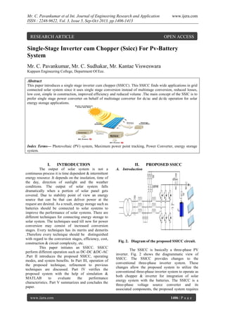
  • 1. Mr. C. Pavankumar et al Int. Journal of Engineering Research and Application ISSN : 2248-9622, Vol. 3, Issue 5, Sep-Oct 2013, pp.1406-1413 RESEARCH ARTICLE www.ijera.com OPEN ACCESS Single-Stage Inverter cum Chopper (Ssicc) For Pv-Battery System Mr. C. Pavankumar, Mr. C. Sudhakar, Mr. Kantae Visweswara Kuppam Engineering College, Department Of Eee. Abstract This paper introduces a single stage inverter cum chopper (SSICC). This SSICC finds wide applications in grid connected solar system since it uses single stage conversion instead of multistage conversion, reduced losses, low cost, simple in construction, improved efficiency and reduced volume .The main concept of the SSIC is to prefer single stage power converter on behalf of multistage converter for dc/ac and dc/dc operation for solar energy storage applications. Index Terms— Photovoltaic (PV) system, Maximum power point tracking, Power Converter, energy storage system. I. INTRODUCTION The output of solar system is not a continuous process it is time dependent & intermittent energy resource .It depends on the insolation, time of the day, direction of sunlight and the weather conditions. The output of solar system falls dramatically when a portion of solar panel gets covered. Due to stability point of view an energy source that can be that can deliver power at the request are desired. As a result, energy storage such as batteries should be connected to solar systems to improve the performance of solar systems. There are different techniques for connecting energy storage to solar system. The techniques used till now for power conversion may consist of increased conversion stages. Every techniques has its merits and demerits .Therefore every technique should be distinguished with regard to the conversion stages, efficiency, cost, construction & circuit complexity, etc. This paper initiates an SSICC. SSICC perform different operation such as DC-DC &DC-AC .Part II introduces the proposed SSICC, operating modes, and system benefits. In Part III, operation of the proposed technique, refinement to previous techniques are discussed. Part IV verifies the proposed system with the help of simulation & MATLAB to evaluate the performance characteristics. Part V summarizes and concludes the paper. www.ijera.com II. PROPOSED SSICC A. Introduction Fig. 2. Diagram of the proposed SSICC circuit. The SSICC is basically a three-phase PV inverter. Fig. 2 shows the diagrammatic view of SSICC. The SSICC provides changes to the conventional three-phase inverter system. These changes allow the proposed system to utilize the conventional three-phase inverter system to operate as both chopper & inverter for integration of solar energy system with the batteries. The SSICC is a three-phase voltage source converter and its associated components, the proposed system requires 1406 | P a g e
  • 2. Mr. C. Pavankumar et al Int. Journal of Engineering Research and Application ISSN : 2248-9622, Vol. 3, Issue 5, Sep-Oct 2013, pp.1406-1413 optional inductors in addition to ac filter inductance B. Switching states of the proposed system The five possible operation modes for the proposed system are as fallows. (a) Mode 1—PV to grid (S1 and S6 switches remain open) (b)Mode 2—PV to battery (switch S6 close & S5, S3 open) (c) Mode 3—PV/battery to grid (switch S6 open & S1, S2, S3, S4 & S5 close) (d) Mode 4—battery to grid (switch S1, S2, S3 & S5 close & S4, S6 open) (a)In Mode 1, the solar panels are directly connected to the grid with maximum power point tracking (MPPT) by a dc/ac operation of the SSICC. www.ijera.com suppose is not enough for the charging purpose. strong asset which helps them to plan and operate the power plant with respect to their needs. The SSICC has reduced conversion stages, high efficiency, low cost & simple in design etc. Fig. 3. Solar energy storage systems with the SSICC and the state-of-the-art solution (b)In Mode 2, the solar panels charge the batteries through dc/dc operation of the converter. In this mode it is possible to track maximum power with the help of MPPT algorithm. D. SYSTEM CONTROL SCHEMES In response to the request of the grid operator, different system control techniques can be realized with the SSICC solar power plants & are as follows: 1)system control 1 for Pgen > Preq ; 2)system control 2 for Pgen < Preq ; 3)system control 3 for Pgen = Preq ; 4) system control 3 for Pgen = 0; (c)In Mode 3 both the solar panels & batteries are connected to the grid by closing the switch S1. (d)Mode 4 delivers the energy stored in the battery to the grid. Fig. 5. System control schemes III. C. Advantages of SSICC The SSICC provides significant merits to solar power plants. The current state-of-the-art technology is to integrate the energy storage into the ac side of the solar system. It can be utilized as a mean for shifting peak hours to solar power plants. This technique allows the system owners to have a www.ijera.com SINGLE STAGE CONVERTER CONTROL A. Control of the proposed system in DC/AC operation modes (modes 1, 3 &4) The dc/ac operation of the SSICC is utilized for delivering power from PV to grid, battery to grid, PV and battery to grid, and grid to battery. The single stage converter performs the MPPT algorithm to deliver maximum power from the PV to the grid. Like the conventional solar inverter control, the SSICC is implemented in the synchronous reference frame. The synchronous reference frame 1407 | P a g e
  • 3. Mr. C. Pavankumar et al Int. Journal of Engineering Research and Application ISSN : 2248-9622, Vol. 3, Issue 5, Sep-Oct 2013, pp.1406-1413 proportional-integral current control is employed. In a reference frame rotating synchronously with the 2. fundamental excitation, the fundamental excitation signals are transformed into dc signals. As a result, the current regulator forming the innermost loop of the control system is able to regulate ac cur-rents over a wide frequency range with high bandwidth and zero steady-state error. For the pulse width modulation (PWM) scheme, the conventional space vector PWM scheme is utilized. Fig. 6 presents the overall control block diagram of the single stage converter in the dc/ac operation. For the dc/ac operation with the battery, the proposed system control should be coordinated with the battery management system (BMS), which is not shown in Fig. 6. B. Control of the proposed system in DC/DC operation modes (modes 2) The dc/dc operation of the single stage converter is also utilized for delivering the maximum power from the solar panels to the battery. The SSICC in the dc/dc operation is a boost converter which controls the current flowing into the battery. In this paper, Li-ion battery has been selected for the solar energy storage systems due to its advantages. Li-ion batteries are charged in two stages www.ijera.com 1. CC CV CC: Applying constant charging current to the battery, until the voltage limit per cell is reached. CV: Apply a constant voltage equal to the maximum cell voltage with respect to the number of cells in series with the battery, as the current gradually falls to chase 0, until the current is less than a set threshold value of about 3% of initial constant charging current. Thus, the dc/dc converter used in charging process must be capable of giving stable control for maintaining either current or voltage at a constant value, depending on the status of the battery. Normally certain capacity losses occur if constant voltage charging is not preferred. However, it is not necessary to avoid constant current charging to simplify the charging control and process. The latter technique can be used to charge batteries, from the control point of view, it is just enough to control only the inductor current. Therefore for charging the Liion batteries the SSICC performs the MPPT algorithm to deliver maximum power from the solar panel to the battery in the dc/dc operation. Fig. 7 shows the overall control circuit of the single stage converter in the dc/dc operation. Fig. 5. Overall control block diagram of the proposed circuit in dc/ac operation. Fig. 7. Overall control block diagram of the proposed circuit for dc/dc operation. C. Design considerations and modifications to conventional three phase inverter for solar battery system: One of the most important requirements of the paper is that the proposed solution must have minimal complexity and modifications to the conventional three-phase solar converter system. www.ijera.com Therefore, it is necessary to investigate how a threephase dc/ac converter operates as a dc/dc converter and what modifications should be made. It is common to use a LCL filter for a high-power three-phase PV converter .Therefore the SSICC in the dc/dc operation is expected to use the inductors already available in the LCL filter. There are basically two types of 1408 | P a g e
  • 4. Mr. C. Pavankumar et al Int. Journal of Engineering Research and Application ISSN : 2248-9622, Vol. 3, Issue 5, Sep-Oct 2013, pp.1406-1413 inductors, coupled three-phase inductor and three single-phase inductors that can be utilized in the single stage converter circuit. TABLE I INDUCTANCE VALUE OF A COUPLED THREEPHASE INDUCTOR IN THE DC/DC OPERATION Using all three phases of the coupled threephase inductor in the dc/dc operation causes a significant drop in the inductance value due to inductor core saturation. Table I presents an example of inductance value of a coupled three-phase inductor for the dc/dc operation, which shows significant drop in the inductance value. The reduction in inductance value requires inserting additional inductors for the dc/dc operation which has been marked as “optional” in Fig. 2. To avoid extra inductors, only one phase can perform the–dc/dc operation. However, when only one phase, for instance phase B, is utilized for the dc/dc operation with only either upper or lower three insulated-gate bipolar transistors (IGBTs) are turned OFF as complementary switching, the circulating current occurs in phases A and C through filter capacitors, the coupled inductor, and switches, resulting in significantly high current ripple in phase B current, as shown in Fig. 8. To prevent the circulating current in the dc/dc operation, the following two solutions are proposed; 1) All unused upper and lower IGBTs must be turned OFF; 2) The coupled inductor is replaced by three singlephase Inductors. While the first solution with a coupled inductor is straight-forward, using three single-phase inductors www.ijera.com makes it possible to use all three phase legs for the dc/dc operation. There are two methods to utilize all three phase legs for the dc/dc operation: 1) Synchronous operation; 2) Interleaving operation. In the first solution, all three phase legs can operate synchronously with their own current control. In this case, the battery can be charged with a higher current compared to the case with one-phase dc/dc operation. This leads to a faster charging time due to higher charging current capability. However, each phase operates with higher current ripples. Higher ripple current flowing into the battery and capacitor can have negative effects on the lifetime of the battery and capacitors. To overcome the aforementioned problem associated with the synchronous operation, phases B and C can be shifted by applying a phase offset. For the interleaving operation using three phase legs, phases B and C are shifted by 120◦ and 240◦, respectively. The inductor current control in interleaving operation re requires a different inductor current sampling scheme, as shown in Fig. 9. However, for three-phase interleaving, a modified sampling scheme is required to measure the average currents for all three phases. Therefore, the sampling points for phases B and C must be shifted by 120 ◦ and 240◦, respectively [see Fig 9(b)], which may imply that computation required inductor current control for each phase should be done asynchronously. Using the interleaving operation reduces the ripples on the charging current flowing into the battery. Therefore, the filter capacitance value can be reduced significantly. D. Mode Change Control The basic concept of the SSICC is to use a single power electronics circuit to perform different operation modes such as PV to grid (dc to ac) and PV to battery (dc to dc) for PV systems with energy storage, as discussed earlier. Therefore, in addition to the converter control in each mode, the seamless transition between modes is also essential for the single stage converter operation. To change a mode, the single stage converter must be reconfigured by either disconnecting or connecting components such as the battery through contactors. Fig. 8. Circulating current path if one phase is used for the dc/dc operation of the proposed circuit with a coupled three-phase inductor. www.ijera.com 1409 | P a g e
  • 5. Mr. C. Pavankumar et al Int. Journal of Engineering Research and Application ISSN : 2248-9622, Vol. 3, Issue 5, Sep-Oct 2013, pp.1406-1413 www.ijera.com Fig. 9. Inductor current sampling schemes in the interleaving operation. (a) Two-phase interleaving. (b) Three-phase interleaving. It is very important to understand the dynamics of the SSICC. Generally, it is necessary to understand the relay response time such as how much time it takes for a relay to completely close or open. Hence, the performance curves of all re-lays used in the SSICC circuit must be investigated. All relays used in the SSICC circuit have a maximum operating time equal to or smaller than 50 ms. All switching, which occur during mode change, are done under zero or nearly zero current, except fault cases. To verify the operating time given in the datasheet of the relays, a test for one of the relays used is made. The operating time of the relay used for SChgDC in Fig. 8 is investigated during pre charging of the inverter capacitors. The captured waveforms are shown in Fig. 10.The relay signal inside the DSP is captured through a D/A converter. It takes 240 μs until the signal reaches a value, 12 V, that is high enough to trigger the relay switching. Once the operating voltage is applied to the relay, it takes 20 ms until the current starts flowing through the relay. In other words, it takes 20 ms for the relay to be fully closed. The measured relay operating time of 20 ms is only half of the value given in the datasheet. For all relays used in the circuit, 80 ms is used as the relay switching transient time for both closing and releasing. The highest layer of the RSC mode change control is shown in Fig. 11. This layer consists of fault detection, fault reset, and normal operation. The basic fault detection such as detecting over current and overvoltage and fault management like turning off PWM signals are implemented inside the converter control executed in the inner most control loop. In this way, fast fault detection and protection are possible. www.ijera.com In general, shutting down all PWM signals is able to clear the fault. In addition, all relays are forced to be opened. If the system is operating normal, the status of the system will be “Normal Condition.” Once the fault flag is set by detecting a fault, the status of the system will be changed to “Fault Condition.” In this status, all relays as well as PWM signals are turned off. When the system is in “Fault Condition,” the single stage converter control tries to clear a fault condition every 1 s. If a fault cannot be cleared, the system will remain in the “Fault Condition.” If a fault is cleared, “Normal Condition” will be reinstated. Inside “Normal Condition,” the system always starts with Mode 0, which is the shutdown mode. This allows the single stage converter to move to a new mode safely, after a fault is cleared. Fig. 12. States inside “Normal Condition.” The control topology inside “Normal Condition” is presented in Fig. 12. The single stage converter control mode can be changed to any mode from the present mode. If Modes 1 or 2 are commanded, the state will change from “Mode 0” to “PVCharge1” and relay “SChgDC” will be closed. This will charge the capacitor “Cdc ” through the resistor “RChgDC.” Once the dc voltage of the capacitor reaches 98% of the source voltage, the state 1410 | P a g e
  • 6. Mr. C. Pavankumar et al Int. Journal of Engineering Research and Application ISSN : 2248-9622, Vol. 3, Issue 5, Sep-Oct 2013, pp.1406-1413 will change to “PVCharge2.” This will also close relay “SPV,” while the re-lay “SChgDC” will remain closed, because no new action refers to this relay. To make sure that the relay “SPV” is fully closed, a delay of 80 ms, relay switching transient time, is used, as discussed earlier. For example, the procedure of Mode 1 is described. Let us assume that the current state is “Mode1pre.” The relay “SChgDC” is opened, so that the pre charging procedure is completed. Also, the three grid-switches “Sag,” “Sbg,” and “Scg” are closed and therefore the load is connected to the single stage converter. Furthermore, the relay “SChg” is opened and the control is set to Mode 1, which is dc/ac control. Because relay switching is included in the state “Mode1pre,” a delay of 80 ms is required to move to the state of “Run Circuit.” When the previous mode is 1, it is possible to directly move to “Mode2pre.” This would bypass the pre charging process since the capacitors of the inverter are required to be connected to the PV side in both modes. All the actions from “Mode2pre” shown in Fig. 12 are executed. After 80 ms, the state moves to “Run Circuit” shown in Fig. 13. When the previous mode is Mode 2 and the new mode is Mode 1, the state directly moves from “PWMOFF” to “Mode1pre” and back to “Run Circuit” by avoiding the pre charge process. The startup of Mode 4 is different from Modes 1 and 2, be-cause it connects the battery to the inverter instead of connecting the PV to it. But the pre charging procedure is quite the same. Only different relays are used—“STran” for charging the capacitor “Cdc ” through the resistance “RTran” and relay “SBat” for directly connecting the battery to the inverter. Then, the state “Mode4pre” closes the grid switches and sets the mode control to number 4, which is again dc/ac control. After “Mode4pre,” the state changes to “Run Circuit.” Going from Modes 1 or 2 to Mode 4 or vice versa is not as easy as the mode change between Modes 1 and 2. The dc voltage always has to be changed to either the battery voltage (coming from Mode 1 or 2) or the PV voltage (coming from Mode 4), which makes the mode change control to use Mode 0 for transition. This does not mean that the circuit needs to be fully de energized, since the pre charging resistances limit the current and can therefore take care of this process. www.ijera.com www.ijera.com IV. PERFORMANCE CHARECTERISTICS OF SSICC The proposed system control algorithms are verified with the help of MATLAB/Simulink. The performance of the SSICC in different operation modes has been tested with the help of MATLAB/Simulink to analyze the performance of SSICC. A. Simulation results of the proposed system in DC/AC Operation Modes (a) (b) (c) Steady-state performance operating modes for the proposed system in DC /AC. (a) Mode 1—PV to grid (b) Mode 3—PV/battery to grid. (c) Mode 4—battery to grid. The above figure shows the steady-state performance of dc/ac control in Mode 1. In this test, the voltage on the dc side VD C of the inverter is set to 200 V. The current reference is set to 5 Ap eak for the frequency of 60 Hz. Fig. a shows the steady-state performance of dc/ac control in Mode 1.. In Fig. b, shows the steady-state performance of dc/ac control in Mode 3. The average battery charging current is 1.8 A. The battery charging current has about 0.85 Apk −pk current ripple with the frequency of 60 Hz. C. Simulation results of the proposed system in DC/DC Operation Mode 1411 | P a g e
  • 7. Mr. C. Pavankumar et al Int. Journal of Engineering Research and Application ISSN : 2248-9622, Vol. 3, Issue 5, Sep-Oct 2013, pp.1406-1413 (a) Steady-state performance operating modes for the proposed system in DC /DC. (a) Mode 2—PV to Battery. In Mode 2 (PV to battery), the three-phase inverter is used as a dc/dc converter. As explained, initially a coupled three-phase inductor is used for the filter inductor to the inverter side. When only phase B is utilized for the dc/dc operation with only either upper or lower three IGBTs are turned off as complementary switching, the circulating current occurs in phases A and C through filter capacitors, the coupled inductor, and switches, resulting in significantly high current ripple in phase B current, as shown in Fig. 18(a). To solve the aforementioned problem, as explained, two solutions are proposed. First, the switches un-used are turned off and consequently the phase current presents much lower ripple as shown in Fig. (b). The average current in phase B is now 5 A with a ripple of 5 Apk −pk while the current in phases A and C remains zero. This means no circulating current. The second solution is to use three single-phase inductors in the SSICC circuit. As expected with single-phase operation in this mode, the circulating current is vanished automatically. The result of the test is presented in Fig. (c) Show that the current in the other phases remains zero while the battery is charged. The average phase B current is 5 A and the average battery current is also 5 A. The phase B ripple is 5 Apk −pk and the battery current ripple is 1.4 Apk −pk . The capacitor ripple current is about 4.2 Apk −pk . Using three single-phase inductors enables the SSICC to use all three phase legs in the dc/dc operation. As discussed earlier, there are two methods to utilize all three phase legs for the dc/dc operation. In the first approach, all three phase-legs operate synchronously with their own current controls. The sum of all three phase currents is 5 A, which means that each phase carries one-third of it. Therefore, it is possible to charge the battery with even a higher current, which leads to a faster charging time. However, each phase current shows the current ripple of 5 Apk −pk · The battery current has the current ripple of 4 Apk −pk and the capacitor current shows the current ripple of 12 Apk −pk which is almost three times as high as the ripple current of the battery charging using a single phase leg. Higher www.ijera.com www.ijera.com ripple current flowing into the battery and capacitor can have negative effects on the lifetime of the battery and capacitors. As discussed earlier, using the interleaving operation can reduce the ripples on the charging current flowing into the battery. Battery current has a ripple current of 0.5 Apk −pk and the capacitor current has a ripple current of 1.5 Apk −pk when the sum of all three phase currents is 5 A and the average battery current is 5 A. These current ripples are one-third of the ripple currents for dc/dc control using a single phase leg and one-eighth of the ripple currents for dc/dc control using all three phase legs in synchronous operation, which means significant ripple reduction is achieved by interleaving operation. V. CONCLUSION This paper proposed a single stage inverter cum chopper for solar- battery application, particularly utility-scale solar-battery application for solar applications. The proposed solution is also suitable to other intermittent energy sources including wind energy. The proposed solution requires simple circuit complexity therefore; the solution is very attractive for solar-battery application, because it has reduced conversion stages, improved efficiency and reduced cost, weight, and volume. The basic concept of the proposed system is to use a single power conversion system instead of multistage conversion system to integrate solar panels with energy storage and grid.. Test results have been presented to verify the concept of the proposed system and to demonstrate the attractive performance characteristics of the proposed system. These results confirm that the proposed system is highly suitable for intermittent energy storage systems. REFERENCES [1] [2] [3] [4] [5] U.S. Department of Energy, “Solar energy grid integration systems-energy storage (SEGIS-ES),” May 2008. D. Bundestag, “Gesetz zur Neuregelung des Rechts der erneuerbaren Energienim Strombereich und zur A¨ nderung damitzusammenha¨ngenderVorschriften,”B undesgesetzblatt, 2008. H. Konishi, T. Iwato, and M. Kudou, “Development of large-scale power conditioning system in Hokuto mega-solar project,” in Proc. Int. Power Electron. Conf., 2010, pp. 1975–1979. J. H. Enslin and D. B. Snyman, “Combined low-cost, high efficient inverter,peak power tracker and regulator for PV applications,” IEEE Trans.Power Electron., vol. 6, no. 1, pp. 73–82, Jan. 1991. H. Ertl, J. W. Kolar, and F. Zach, “A novel multicell dc-ac converter for applications in renewable energy systems,” IEEE Trans. 1412 | P a g e
  • 8. Mr. C. Pavankumar et al Int. Journal of Engineering Research and Application ISSN : 2248-9622, Vol. 3, Issue 5, Sep-Oct 2013, pp.1406-1413 [6] [7] [8] www.ijera.com Ind. Electron.,vol. 49, no. 5, pp. 1048–1057, Oct. 2002. C. Zhao, S. D. Round, and J. W. Kolar, “An isolated three-port bidirectional dc/dc converter with decoupled power flow management,” IEEE Trans. Power Electron., vol. 23, no. 5, pp. 2443–2453, Sep. 2008. M. Bragard, N. Soltau, R. W. De Doncker, and A. Schiemgel, “Design and implementation of a 5 kW photovoltaic system with Li-ion battery and additional dc/dc converter,” in Proc. IEEE Energy Convers. Congr. Expo., 2010, pp. 2944– 2949. W. Li, J. Xiao, Y. Zhao, and X. He, “PWM plus phase angle shift control scheme for combined multiport dc/dc converters, ” IEEE Trans. Power Electron., vol. 27, no. 3, pp. 1479–1489, Mar. 2012. C.Pavankumar has obtained his B.Tech. (Electrical and Electronics Engineering) from kuppam engineering college, JNTUA University, Anathapur in 2009. He is currently pursuing his M.Tech. with specialization of Power Electronics from kuppam engineering college, JNTU Anantapur. His research area of interest includes Power Electronics and Power Systems. C.Sudhakar has obtained his B.Tech.(Electrical and Electronics Engineering) from JNTUA University, Anathapur in 2009. He is currently pursuing his M.Tech. (Power Electronics) from JNTU Anantapur. His research area of interest includes Power Electronics and Power Systems. KANTE VISWESWARA has obtained his B.Tech.(Electrical and Electronics Engineering) from NARAYANA Engineering College, Nellore. in 2006. He completed M.Tech (Energy Systems) in JNTU College Of Engineering, JNTUA, Anantapur in the year 2008. Currently working as Assistant Professor in Kuppam Engineering College in the Department of EEE. His area of research is Energy Auditing, Energy Conservation and Energy Management. www.ijera.com 1413 | P a g e