FPGA based Real-time Automatic Number Plate Recognition System for Modern License Plates in Sri Lanka
•
1 like•304 views

This paper proposes a real-time number plate recognition technique which involves localizing the number plate from a rear view image of a vehicle, processing it using image processing and image enhancement techniques to segment and extract the characters in the number plate which are in turn matched against a set of stored templates for an accurate character recognition process. The entire system is developed on a FPGA to achieve real-time processing.

Recommended
Recommended
More Related Content
What's hot
What's hot (18)
Viewers also liked
Viewers also liked (16)
Similar to FPGA based Real-time Automatic Number Plate Recognition System for Modern License Plates in Sri Lanka
Similar to FPGA based Real-time Automatic Number Plate Recognition System for Modern License Plates in Sri Lanka (20)
Recently uploaded
Recently uploaded (20)
FPGA based Real-time Automatic Number Plate Recognition System for Modern License Plates in Sri Lanka
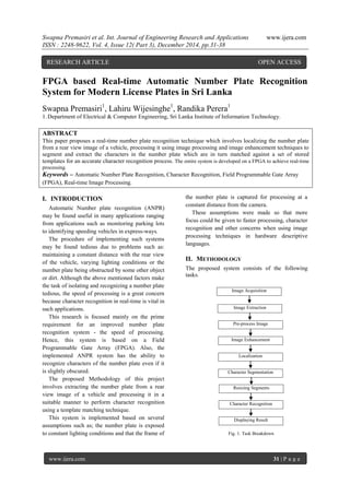
- 1. Swapna Premasiri et al. Int. Journal of Engineering Research and Applications www.ijera.com ISSN : 2248-9622, Vol. 4, Issue 12( Part 3), December 2014, pp.31-38 www.ijera.com 31 | P a g e FPGA based Real-time Automatic Number Plate Recognition System for Modern License Plates in Sri Lanka Swapna Premasiri1 , Lahiru Wijesinghe1 , Randika Perera1 1.Department of Electrical & Computer Engineering, Sri Lanka Institute of Information Technology. ABSTRACT This paper proposes a real-time number plate recognition technique which involves localizing the number plate from a rear view image of a vehicle, processing it using image processing and image enhancement techniques to segment and extract the characters in the number plate which are in turn matched against a set of stored templates for an accurate character recognition process. The entire system is developed on a FPGA to achieve real-time processing. Keywords – Automatic Number Plate Recognition, Character Recognition, Field Programmable Gate Array (FPGA), Real-time Image Processing. I. INTRODUCTION Automatic Number plate recognition (ANPR) may be found useful in many applications ranging from applications such as monitoring parking lots to identifying speeding vehicles in express-ways. The procedure of implementing such systems may be found tedious due to problems such as: maintaining a constant distance with the rear view of the vehicle, varying lighting conditions or the number plate being obstructed by some other object or dirt. Although the above mentioned factors make the task of isolating and recognizing a number plate tedious, the speed of processing is a great concern because character recognition in real-time is vital in such applications. This research is focused mainly on the prime requirement for an improved number plate recognition system - the speed of processing. Hence, this system is based on a Field Programmable Gate Array (FPGA). Also, the implemented ANPR system has the ability to recognize characters of the number plate even if it is slightly obscured. The proposed Methodology of this project involves extracting the number plate from a rear view image of a vehicle and processing it in a suitable manner to perform character recognition using a template matching technique. This system is implemented based on several assumptions such as; the number plate is exposed to constant lighting conditions and that the frame of the number plate is captured for processing at a constant distance from the camera. These assumptions were made so that more focus could be given to faster processing, character recognition and other concerns when using image processing techniques in hardware descriptive languages. II. METHODOLOGY The proposed system consists of the following tasks. RESEARCH ARTICLE OPEN ACCESS Image Extraction Character Segmentation Resizing Segments Image Acquisition Pre-process Image Image Enhancement Localization Character Recognition Displaying Result Fig. 1. Task Breakdown
- 2. Swapna Premasiri et al. Int. Journal of Engineering Research and Applications www.ijera.com ISSN : 2248-9622, Vol. 4, Issue 12( Part 3), December 2014, pp.31-38 www.ijera.com 32 | P a g e 2.1 Image Acquisition A camera was connected to the FPGA board through the composite video port and the video obtained was displayed through the VGA port in a monitor for feed-back. Frames from this video was used for processing. Shown in Fig. 2 is the original image captured from the video that was used for processing. 2.2 Image Extraction This step was necessary to extract or emphasize the number plate from the rear view of the vehicle that is being captured. The equation given below was implemented using Verilog code to perform the above mentioned effect. IB - IGRAY = Extracted Image IGRAY = 0.2989 * R + 0.5870 * G + 0.1140 * B IB = 0 * R + 0 * G + 1* B Equation (2) and (3) states the contribution of R, G and B components towards the pixel values of the images used in equation (1). The image is converted to gray scale by compressing the three layers of the RGB image in to a single layer. Therefore, once subtraction is performed, the extracted image would contain only the regions where the Blue component is comparatively more than the sum of both Red and Green components. The remaining non-black area in the extracted image is equivalent to the yellow region of the original image. The extracted image is shown in Fig. 3. 2.3 Pre-processing the Image This image is converted to a binary image over a suitable threshold, as binary images are easier and simpler to process compared to RGB images. The resulting image is shown in Fig. 4. 2.4 Image Enhancement In this system, Dilation is followed by Erosion. The effects of each technique on the binary image is shown in Fig. 5 and Fig.6. Dilation is performed to eliminate noise in the black and white image. When erosion is performed on the dilated image, the image that was shrunk by dilation was expanded, enhancing the major components of the image. (This enhancement occurs on the characters as they are black). 2.5 Localization For localization, two RAMs were used to store the addition of the pixel values horizontally and vertically. The lines containing more white pixels would have a larger sum. The sum of each horizontal line was saved in a 16 bit register and was sent to the respective address in the RAM. The size of the RAM is chosen to be 1023 addresses of 16 bit registers because the VGA Y addresses created from the VGA controller contains 10 bits. Similarly, the sum of each vertical line is calculated where its sum is saved in a separate RAM having the same size. Fig. 7 gives an overall idea of what is being stored in the two RAMs. Fig. 2. Original Image Fig. 3. Extracted Image (2) (3) (1) Fig. 5. Dilated Image Fig. 6. Eroded Image Fig. 4. Binary Image
- 3. Swapna Premasiri et al. Int. Journal of Engineering Research and Applications www.ijera.com ISSN : 2248-9622, Vol. 4, Issue 12( Part 3), December 2014, pp.31-38 www.ijera.com 33 | P a g e Each RAM would contain the sum of each row and column respective to VGA Y and X. These RAMs get updated along with the VGA clock i.e. once the VGA is read up to 480,640 the summations stored in the RAM are updated. Once data in VGA X is read up to 640, the sum of that line is binarized over a suitable threshold and the binary value is in turn stored in a separate register of 480 bits, which does not change its value within the time of a single frame. Similarly, once data in the Y axis of the VGA is read up to 480, the sum of that column is binarized over a suitable threshold and that binary value is in turn stored in to a separate register of 640 bits, which does not change its value within the time of a single frame. An overview is given in Fig. 8. The final sum is displayed on a VGA monitor and the edges along VGA X and VGA Y are found. (An edge is considered to be the position of the VGA where the value of the array changes) i.e. A rising edge and the following falling edge is found. In this case, the number plate will be isolated because that area tends to contain the most number of white pixels in the binary image. An overview is given in Fig. 9. 1 , 1 479,4 1 , 2 1 , 3 1 , 4 2 , 2 2 , 3 2 , 42 , 2 479 , 1 479 , 2 479,3 480 , 1 480 , 2 480,3 480,4 480,640480,639 479,639 479,640 1,6401,639 2,6402,639 Sum to Xth Location in RAM 2 Fig. 7. - How data are stored in RAMs SumtoYth LocationinRAM2 RAM 1 – Address 001 RAM 1 – Address 002 RAM 1 – Address 003 RAM 1 – Address 480 RAM 1 Horizontal Sum - Bit 001 Horizontal Sum - Bit 002 Horizontal Sum - Bit 003 Horizontal Sum - Bit 480 Final Horizontal Sum Is Sum > Threshold IfYes=1,ElseNo=0 Fig. 8 – Process of Sum of Horizontal Pixels are thresholded to be saved in to an Array
- 4. Swapna Premasiri et al. Int. Journal of Engineering Research and Applications www.ijera.com ISSN : 2248-9622, Vol. 4, Issue 12( Part 3), December 2014, pp.31-38 www.ijera.com 34 | P a g e V Bit 001 V Bit 640 V Bit 001 V Bit 640 V Bit 001 V Bit 640 H Bit 001 H Bit 001 H Bit 002 H Bit 002 H Bit 480 H Bit 480 (a) Bit 00 1 (b) Fig. 9. - Displaying the thresholded final sum of Vertical & Horizontal data Once the rising edge and falling edge along each axis is found, their positions are saved in a separate array. As the coinciding range from the first rising edge to the first falling edge of each axis is now known, the region of the number plate can be identified as shown in Fig. 10. When VGA Data is read along with the clock pulses, if the VGA positions of X are between X1 and X2 and if the VGA positions of Y are between Y1 and Y2, a flag is enabled. AND operation is performed between this flag and the binary image. Therefore, the image which remains for further processing is the resultant image after the AND operation, which will only show the localized number plate. The practical observation of the coinciding regions are shown below in Fig. 11 (a). The localized number plate is shown in Fig. 11 (b). As it can be seen, the region except the number plate remains black where the number plate will consist of only the required information. 2.6 Character Segmentation This was performed by obtaining histograms within the region of the localized number plate, horizontally and vertically. Thus, the lines with most the white spaces (areas that lack black) can be identified. In this approach, VGA data was read again with the VGA clock. Histograms of the isolated region of the number plate were obtained. As it was being read, the sum along the lines were calculated and the sum (16 bit) was not saved separately, instead the sum was thresholded directly via the values given by the switches of the DE2-70 board. This saves memory as only two arrays of sizes 480 and 640 were needed to store the thresholded result. Once these two arrays were displayed on the VGA, characters could be selected as the white regions in between the characters were detected as continuous 1’s. The rising edge and falling edge positions of the horizontal axis were saved in an array and a similar procedure was followed to save vertical edge positions. An overview of this process is given in fig. 12. Y1 Y2 X1 X2 Fig. 10 - Isolating the number Plate ( b ) B it 0 0 1 Fig. 11 - Localizing Number Plate (a) Bit 00 1 (b)
- 5. Swapna Premasiri et al. Int. Journal of Engineering Research and Applications www.ijera.com ISSN : 2248-9622, Vol. 4, Issue 12( Part 3), December 2014, pp.31-38 www.ijera.com 35 | P a g e The camera gives a vertically flipped image of what actually appears. Therefore, the area above Vertical Edge 2 (VE2), is identified as a region containing a number. Similarly, if the area of the number plate is below vertical edge 1 and above vertical edge 4, simultaneously lying in between horizontal edges 3 and 4 and also between 5 and 6, those regions are identified as the regions consisting of characters. This procedure was followed on the assumption that the system detects only vehicles having number plates whose information is distributed in two rows. Shown in Fig. 13 are the segmentations that were observed practically. 2.7 Resizing Segments Along with the VGA clock, the segments were resized and saved in an array. Every 4 pixels in a row of each segmented region (containing 40 pixels in total) are OR operated and saved in a 10 bit array. OR operation is performed on four of these 10 bit registers. Therefore, the resulting resized image would be of 10 x 20 pixels. An overview of the process is given below in Fig. 14. (In this case all segments are assumed to have the same size). Even though this seems like completing one segment and moving on to the next, it happens sequentially, from one segment to the next. Given below is an example of a resized character segment. 2.8 Character Recognition Every segmented number is XORed with all the weights of numbers from 0 - 9, and these XORed data are saved in a separate 2-D array of the same size as the Resized character. A similar procedure was performed for the English characters in the number plate. The weights of each number and character have the same size as the resized number or the character. This is a 10 x 20 matrix obtained from the weights of a trained generalized neural network using Matlab. The weights for a particular number of character will have the same shape as the required numbers or characters. An example for one set of weights (200 bits) that was displayed is shown in Fig. 16. The sum of 1’s in each XORed character is calculated. If the XORed sum has a minimum value when compared to other summations, it means that the segmented character is closest to the particular weight that it was XORed with. Thus, the character can be recognized, as the value corresponding to each set (pattern) of weights are predefined. An example of XORed data for a single character is shown in Fig. 17. Part (a) of this image shows when a segmented 4 is XORed with weights corresponding to 7 which is not a match. Horizontal Edge (HE) K M 2 6 0 8 VE 1 VE 2 VE 3 VE 4 VerticalEdge(VE) HE 1,2 HE 3,4 HE 7,8 HE 9,10 Fig. 12 – Detected Edge Positions on Isolated Number Plate Fig. 13 - Segmented Characters Fig. 15 - Resized Character Segment Fig. 16 - Weights for No. 7 40 pixels in X axis between Edge positions in Y axis 5×5 pixels Fig. 14 - Resizing Image Line Array (LA) LA 01 LA 02 LA 40
- 6. Swapna Premasiri et al. Int. Journal of Engineering Research and Applications www.ijera.com ISSN : 2248-9622, Vol. 4, Issue 12( Part 3), December 2014, pp.31-38 www.ijera.com 36 | P a g e Part (b) shows the result when a segmented number 4 is XORed with weights corresponding to 4 which is a match. The best match for that particular segment is said to be 4 because the resultant sum of the pixels of XORed data is less in the second image (b). The best match for that particular segment is said to be 4 because the resultant sum of the pixels of XORed data is less in the second image (b). An overview of the procedure followed for a single character (1st segment – character 1) is given below in Fig 18. (XORed Sum 1 is assumed to be initially zero in the process described below) . 2.9 Displaying the Result The results were displayed on the Liquid Crystal Display (LCD) of a DE2-70 FPGA Board using suitable Verilog code where the binary value was passed to the LCD module every time a character was recognized. Given in Fig. 19 is an example of how results were obtained for recognized number plates. Resized Character 1 (Segment 1) Weights of Number 2 Weights of Number 3 Weights of Number 9 Weights of Number 1 XORed Sum 1 Char 1 = Output + XORed Sum 1 Char 1 XORed Sum 2 Char 1 = Output + XORed Sum 1 Char 1 XORed Sum 3 Char 1 = Output + XORed Sum 1 Char 1 XORed Sum 9 Char 1 = Output + XORed Sum 1 Char 1 XORed Sum 1 for Char 1 XORed Sum 2 for Char 1 XORed Sum 3 for Char 1 XORed Sum 9 for Char 1 Find Minimum XORed Sum Min Sum = Sum 1 Min Sum = Sum2 Min Sum = Sum 3 Min Sum = Sum 9 Yes Yes Yes Yes Fig. 18 – The process of Character Recognition Output = Number 1 Output = Number 2 Output = Number 3 Output = Number 9 XORed Data Weights Resized Segmented Character Fig. 17 - Localized Number Plate (a) (b)
- 7. Swapna Premasiri et al. Int. Journal of Engineering Research and Applications www.ijera.com ISSN : 2248-9622, Vol. 4, Issue 12( Part 3), December 2014, pp.31-38 www.ijera.com 37 | P a g e III. RESULTS Table I shows the hardware usage for this system in terms of logic and memory elements. TABLE I HARDWARE UTILIZATION OF THE DE2-70 FPGA BOARD Components Used Available Utilisation Logic Elements 16796 68416 25% Memory Bits 123508 1152000 11% The accuracy of the three main tasks of this system, namely, Localization, Pre-processing & Character Recognition was tested individually on 40 number plate variations. The success rate of each sub-process was analyzed before concluding the overall success rate of the implemented system based on the proposed methodology in this paper. TABLE II TEST RESULTS Task Samples Failure Rate Success Rate Localization 40 Pre-processing (Segmentation) 34 Character Recognition 53 TABLE III EXAMPLE IMAGES FOR TEST RESULTS Task Failure - Example Success - Example Localization Pre-processing (Segmentation) Character Recognition Considering an average of the test results in all three tasks, it was proven that this method has the ability to reach an overall success rate of 89.9 %. IV. CONCLUSION & FURTHER WORK In this system, VGA data was read with the VGA clock and histograms of the isolated number plate were taken. As it was being read, the sum along the lines were calculated and the sum was saved in to a RAM. Similarly, VGA Y data was read along with the clock and was saved in to a separate RAM. The data stored in the RAM were thresholded immediately and only the binarized result was saved in separate 1-D arrays of sizes 640 and 480 which optimizes the use of logic elements in the device. From the results of this number plate recognition system, it could be concluded that the system is about 90 % accurate within the specified conditions. If the reliability of the system waivered, it was due to the fluctuations in the environment, as the system was implemented assuming that certain environmental factors would remain constant (stated in the introduction). This system was faster compared to a similar system implemented using Matlab code because even the longest process in the Verilog code consumes only about hundred 50 MHz clock cycles, which is less than the time of a frame. This proves that the implemented system can perform in real- time. In conclusion, the functionality of this system is as expected, provided that the system functions within the given assumptions. As the speed of processing is high and results are provided in real- time, a further improved system can be obtained by extending the features suggested as further work. 3.1. Further Work As this system depends on environmental factors such as lighting conditions, this system could be further developed to function with an automatic thresholding technique. Also, an assumption has been made that the number plate is always at a constant distance to the camera. Therefore, more features could be added to auto adjust the camera or to extend the ability to recognize characters of the number plate from varying distances. Another improvement that would take this project to a next level is improving the neural network by improving more training images of characters (weights) and by introducing weights for a single character with more variations. Fig. 20. Fail E.g.1 Fig. 21. Success E.g.1 Fig. 23. Success E.g.2Fig.22. Fail E.g.2 Fig.24. Fail E.g.3 Fig. 25. Success E.g.3
- 8. Swapna Premasiri et al. Int. Journal of Engineering Research and Applications www.ijera.com ISSN : 2248-9622, Vol. 4, Issue 12( Part 3), December 2014, pp.31-38 www.ijera.com 38 | P a g e REFERENCES Journal Papers: [1] R. Kumar, R. Prasad, D. Signh, A Radial Basis Function Approach to Retrieve Soil Moisture and Crop Variables from X-band Scatterometer Observations, Progress in Electromagnetic Research, 12, 2009, 201-207. [2] Shan Du, Mahamoud Ibrahim, Mohamed Shehata, Wael Badawy, Automatic License Plate Recognition (ALPR): A State-of-Art Review, IEEE, 23, 2013, 311-325. [3] Xiaojun Zhai, Faycal Bensaali, Soodamani Ramalingam, Improved Number Plate Localization Alogrithm and its Efficient Field Programmable Gate Arrays Implementation , Canadian Conference on Electrical & Computer Engineering, Toronto, Canada, IEEE, 2014, 093-103. Proceedings Papers: [4] Sahil Shaikh, Bornika Lahiri, Gopi Bhatt, Nirav Raja, A Novel Approach for Automatic Number Plate Recognition, International conference on Intelligent systems and Signal Processing, Gujarat, India, 2013, 375 – 380 [5] Nazadin Yazdian, Yun Tie, Venetsanopoulos Anastasios, Ling Guan, Automatic Ontario License Plate Recognition using local Normalization and Intelligent Character Classification, Canadian Conference on Electrical & Computer Engineering, Toronto, Canada, IEEE, 2014, 001-006. Electronic Documents: [6] Xiaofan Bao, Jiayuan Wang, “Real-time Photoshop: An FPGA-based Real-time Morphological Image Processor,” Cornell University Electrical & Computer Engineering, 2013. [Online]. Available: http://people.ece.cornell.edu/land/courses/ece5 760/FinalProjects/s2013/ [Accessed: October 23, 2014]. [7] “Altera official site,”1995-2014. [Online]. Available: http://www.altera.com [Accessed: Nov. 05, 2014]