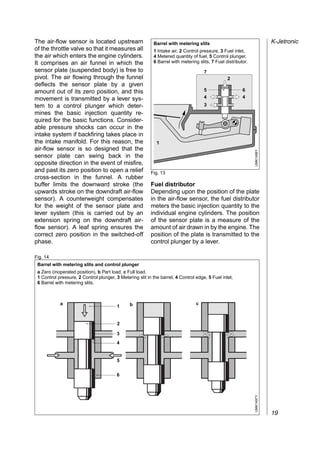
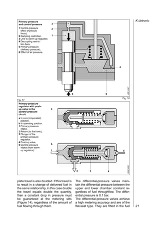
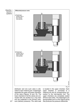
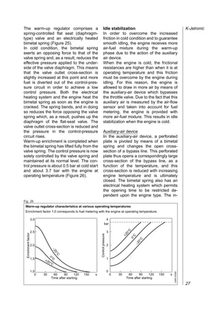
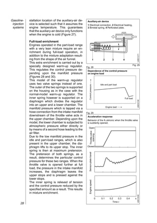
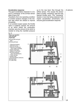
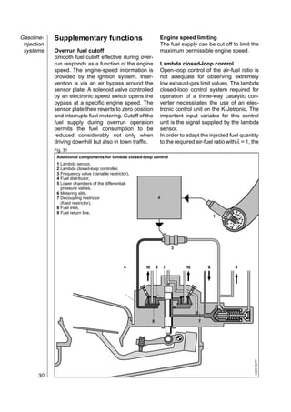
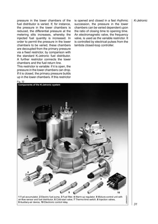
Gasoline-engine management


Gasoline Fuel-Injection
System K-Jetronic


Technical Instruction
Published by:
© Robert Bosch GmbH, 2000
Postfach 30 02 20,
D-70442 Stuttgart.
Automotive Equipment Business Sector,
Department for Automotive Services,
Technical Publications (KH/PDI2).

Editor-in-Chief:
Dipl.-Ing. (FH) Horst Bauer.

Editorial staff:
Dipl.-Ing. Karl-Heinz Dietsche,
Dipl.-Ing. (BA) Jürgen Crepin.

Presentation:
Dipl.-Ing. (FH) Ulrich Adler,
Joachim Kaiser,
Berthold Gauder, Leinfelden-Echterdingen.

Translation:
Peter Girling.

Technical graphics:
Bauer & Partner, Stuttgart.

Unless otherwise stated, the above are all
employees of Robert Bosch GmbH, Stuttgart.


Reproduction, copying, or translation of this
publication, including excerpts therefrom, is only to
ensue with our previous written consent and with
source credit.
Illustrations, descriptions, schematic diagrams,
and other data only serve for explanatory purposes
and for presentation of the text. They cannot be
used as the basis for design, installation, or scope
of delivery. We assume no liability for conformity of
the contents with national or local legal regulations.
We are exempt from liability.
We reserve the right to make changes at any time.

Printed in Germany.
Imprimé en Allemagne.

4th Edition, February 2000.
English translation of the German edition dated:
September 1998.
K-Jetronic


Since its introduction, the K-Jetronic    Combustion in the gasoline engine
gasoline-injection system has pro-        The spark-ignition or
ved itself in millions of vehicles.       Otto-cycle engine                  2
This development was a direct result      Gasoline-engine management
of the advantages which are inherent      Technical requirements             4
in the injection of gasoline with         Cylinder charge                    5
regard to demands for economy of          Mixture formation                  7
operation, high output power, and         Gasoline-injection systems
last but not least improvements to        Overview                          10
the quality of the exhaust gases          K-Jetronic
emitted by the vehicle. Whereas the       System overview                   13
call for higher engine output was the     Fuel supply                       14
foremost consideration at the start of    Fuel metering                     18
the development work on gasoline          Adapting to operating conditions  24
injection, today the target is to         Supplementary functions           30
achieve higher fuel economy and           Exhaust-gas treatment             32
lower toxic emissions.                    Electrical circuitry              36
Between the years 1973 and 1995,          Workshop testing techniques       38
the highly reliable, mechanical multi-
point injection system K-Jetronic
was installed as Original Equipment
in series-production vehicles. Today,
it has been superseded by gasoline
injection systems which thanks to
electronics have been vastly im-
proved and expanded in their func-
tions. Since this point, the K-Jetronic
has now become particularly impor-
tant with regard to maintenance and
repair.

This manual will describe the
K-Jetronic’s function and its particu-
lar features.
Combustion in
  the gasoline
       engine
                 Combustion in
                 the gasoline engine

                                                                          combustion process pressurizes the
                 The spark-ignition                                       cylinder, propelling the piston back down,
                 or Otto-cycle engine                                     exerting force against the crankshaft and
                                                                          performing work. After each combustion
                                                                          stroke the spent gases are expelled from
                 Operating concept                                        the cylinder in preparation for ingestion of
                 The spark-ignition or Otto-cycle1)                       a fresh charge of air/fuel mixture. The
                 powerplant is an internal-combustion (IC)                primary design concept used to govern
                 engine that relies on an externally-                     this gas transfer in powerplants for
                 generated ignition spark to transform the                automotive applications is the four-stroke
                 chemical energy contained in fuel into                   principle, with two crankshaft revolutions
                 kinetic energy.                                          being required for each complete cycle.
                 Today’s standard spark-ignition engines
                 employ manifold injection for mixture
                 formation outside the combustion
                                                                          The four-stroke principle
                 chamber. The mixture formation system                    The four-stroke engine employs flow-
                 produces an air/fuel mixture (based on                   control valves to govern gas transfer
                 gasoline or a gaseous fuel), which is                    (charge control). These valves open and
                 then drawn into the engine by the suction                close the intake and exhaust tracts
                 generated as the pistons descend. The                    leading to and from the cylinder:
                 future will see increasing application of
                 systems that inject the fuel directly into the           1st stroke:    Induction,
                 combustion chamber as an alternate                       2nd stroke:    Compression and ignition,
                 concept. As the piston rises, it compresses              3rd stroke:    Combustion and work,
                 the mixture in preparation for the timed                 4th stroke:    Exhaust.
                 ignition process, in which externally-
                 generated energy initiates combustion via                Induction stroke
                 the spark plug. The heat released in the                 Intake valve: open,
                 Fig. 1                                                   Exhaust valve: closed,
                  Reciprocating piston-engine design concept              Piston travel: downward,
                  OT = TDC (Top Dead Center); UT = BDC (Bottom            Combustion: none.
                  Dead Center), Vh Swept volume, VC Compressed
                  volume, s Piston stroke.                                The piston’s downward motion increases
                                                  VC
                            OT                                            the cylinder’s effective volume to draw
                                                                          fresh air/fuel mixture through the passage
                                                s                         exposed by the open intake valve.
                           Vh
                           UT                                             Compression stroke
                                                                          Intake valve: closed,
                                                                          Exhaust valve: closed,
                                       OT                                 Piston travel: upward,
                                                                          Combustion: initial ignition phase.
                                                               UMM0001E


                                                                          1)  After Nikolaus August Otto (1832 –1891), who
                                       UT                                 unveiled the first four-stroke gas-compression engine
            2                                                             at the Paris World Exhibition in 1876.
As the piston travels upward it reduces                The ignition spark at the spark plug                   Otto cycle
the cylinder’s effective volume to                     ignites the compressed air/fuel mixture,
compress the air/fuel mixture. Just before             thus initiating combustion and the
the piston reaches top dead center (TDC)               attendant temperature rise.
the spark plug ignites the concentrated                This raises pressure levels within the
air/fuel mixture to initiate combustion.               cylinder to propel the piston downward.
Stroke volume Vh                                       The piston, in turn, exerts force against
and compression volume VC                              the crankshaft to perform work; this
provide the basis for calculating the                  process is the source of the engine’s
compression ratio                                      power.
ε = (Vh+VC)/VC.                                        Power rises as a function of engine speed
Compression ratios ε range from 7...13,                and torque (P = M⋅ω).
depending upon specific engine design.                 A transmission incorporating various
Raising an IC engine’s compression ratio               conversion ratios is required to adapt the
increases its thermal efficiency, allowing             combustion engine’s power and torque
more efficient use of the fuel. As an                  curves to the demands of automotive
example, increasing the compression ratio              operation under real-world conditions.
from 6:1 to 8:1 enhances thermal
efficiency by a factor of 12 %. The latitude           Exhaust stroke
for increasing compression ratio is                    Intake valve: closed,
restricted by knock. This term refers to               Exhaust valve: open,
uncontrolled mixture inflammation charac-              Piston travel: upward,
terized by radical pressure peaks.                     Combustion: none.
Combustion knock leads to engine
damage. Suitable fuels and favorable                   As the piston travels upward it forces the
combustion-chamber configurations can                  spent gases (exhaust) out through the
be applied to shift the knock threshold into           passage exposed by the open exhaust
higher compression ranges.                             valve. The entire cycle then recommences
                                                       with a new intake stroke. The intake and
Power stroke                                           exhaust valves are open simultaneously
Intake valve: closed,                                  during part of the cycle. This overlap
Exhaust valve: closed,                                 exploits gas-flow and resonance patterns
Piston travel: upward,                                 to promote cylinder charging and
Combustion: combustion/post-combus-                    scavenging.
tion phase.

Fig. 2
 Operating cycle of the 4-stroke spark-ignition engine

         Stroke 1: Induction   Stroke 2: Compression    Stroke 3: Combustion   Stroke 4: Exhaust
                                                                                                   UMM0011E


                                                                                                              3
Gasoline-
     engine
management
              Gasoline-
              engine management
              Technical requirements                                            Primary engine-
                                                                                management functions
                                                                                The engine-management system’s first
              Spark-ignition (SI)                                               and foremost task is to regulate the
              engine torque                                                     engine’s torque generation by controlling
                                                                                all of those functions and factors in the
              The power P furnished by the spark-                               various engine-management subsystems
              ignition engine is determined by the                              that determine how much torque is
              available net flywheel torque and the                             generated.
              engine speed.
              The net flywheel torque consists of the                           Cylinder-charge control
              force generated in the combustion                                 In Bosch engine-management systems
              process minus frictional losses (internal                         featuring electronic throttle control (ETC),
              friction within the engine), the gas-                             the “cylinder-charge control” subsystem
              exchange losses and the torque required                           determines the required induction-air
              to drive the engine ancillaries (Figure 1).                       mass and adjusts the throttle-valve
              The combustion force is generated                                 opening accordingly. The driver exercises
              during the power stroke and is defined by                         direct control over throttle-valve opening
              the following factors:                                            on conventional injection systems via the
              – The mass of the air available for                               physical link with the accelerator pedal.
                 combustion once the intake valves
                 have closed,                                                   Mixture formation
              – The mass of the simultaneously                                  The “mixture formation” subsystem cal-
                 available fuel, and                                            culates the instantaneous mass fuel
              – The point at which the ignition spark                           requirement as the basis for determining
                 initiates combustion of the air/fuel                           the correct injection duration and optimal
                 mixture.                                                       injection timing.
              Fig. 1
               Driveline torque factors
               1 Ancillary equipment                    1      1       2        3           4
                 (alternator,
                 a/c compressor, etc.),
               2 Engine,
               3 Clutch,
               4 Transmission.


                Air mass (fresh induction charge)
                                                             Combustion      Engine        Flywheel                    Drive
                Fuel mass                                    output torque   output torque torque              Trans- force
                                                    Engine                                            Clutch
                                                                              –             –              –   mission
                                                                                                                   –
                Ignition angle (firing point)
                                                                                                           –        –

                Gas-transfer and friction
                Ancillaries
                                                                                                                               UMM0545-1E


                Clutch/converter losses and conversion ratios
                Transmission losses and conversion ratios
         4
Ignition                                            emissions control system (Figure 2). The              Cylinder
Finally, the “ignition” subsystem de-               air entering through the throttle-valve and           charge
termines the crankshaft angle that                  remaining in the cylinder after intake-
corresponds to precisely the ideal instant          valve closure is the decisive factor
for the spark to ignite the mixture.                defining the amount of work transferred
                                                    through the piston during combustion,
The purpose of this closed-loop control             and thus the prime determinant for the
system is to provide the torque                     amount of torque generated by the
demanded by the driver while at the                 engine. In consequence, modifications to
same time satisfying strict criteria in the         enhance maximum engine power and
areas of                                            torque almost always entail increasing
– Exhaust emissions,                                the maximum possible cylinder charge.
– Fuel consumption,                                 The theoretical maximum charge is
– Power,                                            defined by the volumetric capacity.
– Comfort and convenience, and
– Safety.                                           Residual gases
                                                    The portion of the charge consisting of
                                                    residual gases is composed of
                                                    – The exhaust-gas mass that is not
Cylinder charge                                        discharged while the exhaust valve is
                                                       open and thus remains in the cylinder,
Elements                                               and
The gas mixture found in the cylinder               – The mass of recirculated exhaust gas
once the intake valve closes is referred to            (on systems with exhaust-gas recircu-
as the cylinder charge, and consists of                lation, Figure 2).
the inducted fresh air-fuel mixture along           The proportion of residual gas is de-
with residual gases.                                termined by the gas-exchange process.
                                                    Although the residual gas does not
Fresh gas                                           participate directly in combustion, it does
The fresh mixture drawn into the cylinder           influence ignition patterns and the actual
is a combination of fresh air and the fuel          combustion sequence. The effects of this
entrained with it. While most of the fresh          residual-gas component may be thoroughly
air enters through the throttle valve,              desirable under part-throttle operation.
supplementary fresh gas can also be                 Larger throttle-valve openings to com-
drawn in through the evaporative-                   pensate for reductions in fresh-gas filling
Fig. 2
 Cylinder charge in the spark-ignition engine
  1 Air and fuel vapor,
  2 Purge valve
    with variable aperture,                                                 2         3
  3 Link to evaporative-emissions
    control system,                                        1
  4 Exhaust gas,
  5 EGR valve with                                     α           4        5
    variable aperture,
  6 Mass airflow (barometric pressure pU),                             11       12
  7 Mass airflow
    (intake-manifold pressure ps),              6              7                     10
  8 Fresh air charge                                                        8
    (combustion-chamber pressure pB),
  9 Residual gas charge                                                     9
    (combustion-chamber pressure pB),
 10 Exhaust gas (back-pressure pA),
                                                                                             UMM0544-1Y


 11 Intake valve,
 12 Exhaust valve,
 α Throttle-valve angle.
                                                                                                          5
Gasoline-   are needed to meet higher torque                on a supplementary EGR valve linking
     engine   demand. These higher angles reduce the          the intake and exhaust manifolds. The
management    engine’s pumping losses, leading to             engine ingests a mixture of fresh air and
              lower fuel consumption. Precisely reg-          exhaust gas when this valve is open.
              ulated injection of residual gases can
              also modify the combustion process to           Pressure charging
              reduce emissions of nitrous oxides (NOx)        Because maximum possible torque is
              and unburned hydrocarbons (HC).                 proportional to fresh-air charge density, it
                                                              is possible to raise power output by
                                                              compressing the air before it enters the
              Control elements                                cylinder.

              Throttle valve                                  Dynamic pressure charging
              The power produced by the spark-                A supercharging (or boost) effect can be
              ignition engine is directly proportional to     obtained by exploiting dynamics within
              the mass airflow entering it. Control of        the intake manifold. The actual degree of
              engine output and the corresponding             boost will depend upon the manifold’s
              torque at each engine speed is regulated        configuration as well as the engine’s
              by governing the amount of air being            instantaneous        operating       point
              inducted via the throttle valve. Leaving        (essentially a function of the engine’s
              the throttle valve partially closed restricts   speed, but also affected by load factor).
              the amount of air being drawn into the          The option of varying intake-manifold
              engine and reduces torque generation.           geometry while the vehicle is actually
              The extent of this throttling effect            being driven, makes it possible to employ
              depends on the throttle valve’s position        dynamic precharging to increase the
              and the size of the resulting aperture.         maximum available charge mass through
              The engine produces maximum power               a wide operational range.
              when the throttle valve is fully open
              (WOT, or wide open throttle).                   Mechanical supercharging
              Figure 3 illustrates the conceptual             Further increases in air mass are
              correlation between fresh-air charge            available through the agency of
              density and engine speed as a function          Fig. 3
              of throttle-valve aperture.                      Throttle-valve map for spark-ignition engine
                                                                                   Throttle valve at intermediate aperture
              Gas exchange
              The intake and exhaust valves open and
              close at specific points to control the
              transfer of fresh and residual gases. The                                       Throttle valve
              ramps on the camshaft lobes determine                                           completely open
              both the points and the rates at which the
              valves open and close (valve timing) to
              define the gas-exchange process, and
                                                                Fresh gas charge


              with it the amount of fresh gas available
              for combustion.
              Valve overlap defines the phase in which
              the intake and exhaust valves are open
              simultaneously, and is the prime factor in
              determining the amount of residual gas
              remaining in the cylinder. This process is
              known      as    "internal"  exhaust-gas                                        Throttle valve
                                                                                                                              UMM0543-1E


              recirculation. The mass of residual gas                                         completely closed

              can also be increased using "external"                               min.                                max.
         6    exhaust-gas recirculation, which relies                                 Idle             RPM
mechanically driven compressors pow-
ered by the engine’s crankshaft, with the
                                                                              Mixture formation                             Mixture
                                                                                                                            formation
two elements usually rotating at an in-
variable relative ratio. Clutches are often
used to control compressor activation.
                                                                              Parameters
Exhaust-gas turbochargers                                                     Air-fuel mixture
Here the energy employed to power the                                         Operation of the spark-ignition engine is
compressor is extracted from the exhaust                                      contingent upon availability of a mixture
gas. This process uses the energy that                                        with a specific air/fuel (A/F) ratio. The
naturally-aspirated     engines     cannot                                    theoretical ideal for complete combustion
exploit directly owing to the inherent                                        is a mass ratio of 14.7:1, referred to as
restrictions imposed by the gas ex-                                           the stoichiometric ratio. In concrete terms
pansion characteristics resulting from the                                    this translates into a mass relationship of
crankshaft concept. One disadvantage is                                       14.7 kg of air to burn 1 kg of fuel, while
the higher back-pressure in the exhaust                                       the corresponding volumetric ratio is
gas exiting the engine. This back-                                            roughly 9,500 litres of air for complete
pressure stems from the force needed to                                       combustion of 1 litre of fuel.
maintain compressor output.
The exhaust turbine converts the                                              The air-fuel mixture is a major factor in
exhaust-gas energy into mechanical                                            determining the spark-ignition engine’s
energy, making it possible to employ an                                       rate of specific fuel consumption.
impeller to precompress the incoming                                          Genuine complete combustion and
fresh air. The turbocharger is thus a                                         absolutely minimal fuel consumption
combination of the turbine in the exhaust-                                    would be possible only with excess air,
fas flow and the impeller that compresses                                     but here limits are imposed by such
the intake air.                                                               considerations as mixture flammability
Figure 4 illustrates the differences in the                                   and the time available for combustion.
torque curves of a naturally-aspirated
engine and a turbocharged engine.                                             The air-fuel mixture is also vital in
                                                                              determining the efficiency of exhaust-gas
Fig. 4                                                                        treatment system. The current state-of-
 Torque curves for turbocharged                                               the-art features a 3-way catalytic
 and atmospheric-induction engines                                            converter, a device which relies on a
 with equal power outputs                                                     stoichiometric A/F ratio to operate at
 1 Engine with turbocharger,                                                  maximum efficiency and reduce un-
 2 Atmospheric-induction engine.
                                                                              desirable exhaust-gas components by
                                                                              more than 98 %.

                                                                              Current engines therefore operate with a
                                                                              stoichiometric A/F ratio as soon as the
                                      1                                       engine’s operating status permits
  Engine torque Md


                                                                              Certain engine operating conditions
                                             2                                make mixture adjustments to non-
                                                                              stoichiometric ratios essential. With a
                                                                              cold engine for instance, where specific
                                                                              adjustments to the A/F ratio are required.
                                                                              As this implies, the mixture-formation
                                                                              system must be capable of responding to
                                                                 UMM0459-1E


                     1            1              3       1
                         4            2              4       1                a range of variable requirements.
                             Engine rpm nn
                                                                                                                            7
Gasoline-   Excess-air factor                                                          deficiencies of 5...15 % (λ = 0.95...0.85),
     engine   The designation l (lambda) has been                                        but maximum fuel economy comes in at
management    selected to identify the excess-air factor                                 10...20 % excess air (λ = 1.1...1.2).
              (or air ratio) used to quantify the spread                                 Figures 1 and 2 illustrate the effect of the
              between the actual current mass A/F ratio                                  excess-air factor on power, specific fuel
              and the theoretical optimum (14.7:1):                                      consumption and generation of toxic
              λ = Ratio of induction air mass to air                                     emissions. As can be seen, there is no
              requirement for stoichiometric com-                                        single excess-air factor which can
              bustion.                                                                   simultaneously generate the most
              λ = 1: The inducted air mass corresponds                                   favorable levels for all three factors. Air
              to the theoretical requirement.                                            factors of λ = 0.9...1.1 produce
              λ < 1: Indicates an air deficiency,                                        “conditionally optimal” fuel economy with
              producing a corresponding rich mixture.                                    “conditionally optimal” power generation
              Maximum power is derived from λ =                                          in actual practice.
              0.85...0.95.                                                               Once the engine warms to its normal
              λ > 1: This range is characterized by                                      operating temperature, precise and
              excess air and lean mixture, leading to                                    consistent maintenance of λ = 1 is vital
              lower fuel consumption and reduced                                         for the 3-way catalytic treatment of
              power. The potential maximum value for λ                                   exhaust gases. Satisfying this re-
              – called the “lean-burn limit (LML)” – is                                  quirement entails exact monitoring of
              essentially defined by the design of the                                   induction-air mass and precise metering
              engine and of its mixture for-                                             of fuel mass.
              mation/induction system. Beyond the                                        Optimal combustion from current en-
              lean-burn limit the mixture ceases to be                                   gines equipped with manifold injection
              ignitable and combustion miss sets in,                                     relies on formation of a homogenous
              accompanied by substantial degener-                                        mixture as well as precise metering of the
              ation of operating smoothness.                                             injected fuel quantity. This makes
              In engines featuring systems to inject fuel                                effective atomization essential. Failure to
              directly into the chamber, these operate                                   satisfy this requirement will foster the
              with substantially higher excess-air                                       formation of large droplets of condensed
              factors (extending to λ = 4) since com-                                    fuel on the walls of the intake tract and in
              bustion proceeds according to different                                    the combustion chamber. These droplets
              laws.                                                                      will fail to combust completely and the
              Spark-ignition engines with manifold                                       ultimate result will be higher HC
              injection produce maximum power at air                                     emissions.
              Fig. 1                                                                     Fig. 2
               Effects of excess-air factor λ on power P and                              Effect of excess-air factor λ on untreated
               specific fuel consumption be.                                              exhaust emissions
               a Rich mixture (air deficiency),
               b Lean mixture (excess air).

                                                                                                                          HC               NOX
                                                                                                                     CO
               Specific fuel consumption be


                                                                  P
                                                                                           Relative quantities of


                                                                  be
                                                                                           CO; HC; NOX
               Power P ,


                                                      a           b
                                                                              UMK0033E


                                                                                                                                                            UMK0032E


                                              0.8          1.0          1.2                                         0.6   0.8       1.0        1.2    1.4
                                                    Excess-air factor λ                                                         Excess-air factor λ
         8
Adapting to specific                           Idle and part-load                               Mixture
operating conditions                           Idle is defined as the operating status in       formation
                                               which the torque generated by the engine
Certain operating states cause fuel            is just sufficient to compensate for friction
requirements to deviate substantially from     losses. The engine does not provide
the steady-state requirements of an engine     power to the flywheel at idle. Part-load (or
warmed to its normal temperature, thus         part-throttle) operation refers to the
necessitating corrective adaptations in the    range of running conditions between idle
mixture-formation apparatus. The follow-       and generation of maximum possible
ing descriptions apply to the conditions       torque. Today’s standard concepts rely
found in engines with manifold injection.      exclusively on stoichiometric mixtures for
                                               the operation of engines running at idle
Cold starting                                  and part-throttle once they have warmed
During cold starts the relative quantity of    to their normal operating temperatures.
fuel in the inducted mixture decreases: the
mixture “goes lean.” This lean-mixture         Full load (WOT)
phenomenon stems from inadequate               At WOT (wide-open throttle) supple-
blending of air and fuel, low rates of fuel    mentary enrichment may be required. As
vaporization, and condensation on the          Figure 1 indicates, this enrichment
walls of the inlet tract, all of which are     furnishes maximum torque and/or power.
promoted by low temperatures. To com-
pensate for these negative factors, and to     Acceleration and deceleration
facilitate cold starting, supplementary fuel   The fuel’s vaporization potential is strongly
must be injected into the engine.              affected by pressure levels inside the
                                               intake manifold. Sudden variations in
Post-start phase                               manifold pressure of the kind encountered
Following     low-temperature      starts,     in response to rapid changes in throttle-
supplementary fuel is required for a brief     valve aperture cause fluctuations in the
period, until the combustion chamber           fuel layer on the walls of the intake tract.
heats up and improves the internal             Spirited acceleration leads to higher
mixture formation. This richer mixture         manifold pressures. The fuel responds
also increases torque to furnish a             with lower vaporization rates and the fuel
smoother transition to the desired idle        layer within the manifold runners expands.
speed.                                         A portion of the injected fuel is thus lost in
                                               wall condensation, and the engine goes
Warm-up phase                                  lean for a brief period, until the fuel layer
The warm-up phase follows on the heels         restabilizes. In an analogous, but inverted,
of the starting and immediate post-start       response pattern, sudden deceleration
phases. At this point the engine still         leads to rich mixtures. A temperature-
requires an enriched mixture to offset the     sensitive correction function (transition
fuel condensation on the intake-manifold       compensation) adapts the mixture to
walls. Lower temperatures are synony-          maintain optimal operational response
mous with less efficient fuel proces-          and ensure that the engine receives the
sing (owing to factors such as poor mix-       consistent air/fuel mixture needed for
ing of air and fuel and reduced fuel va-       efficient catalytic-converter performance.
porization). This promotes fuel precip-
itation within the intake manifold, with       Trailing throttle (overrun)
the formation of condensate fuel that will     Fuel metering is interrupted during trailing
only vaporize later, once temperatures         throttle. Although this expedient saves
have increased. These factors make it          fuel on downhill stretches, its primary
necessary to provide progressive mixture       purpose is to guard the catalytic converter
enrichment in response to decreasing           against overheating stemming from poor
temperatures.                                  and incomplete combustion (misfiring).           9
Gasoline-
 injection
 systems
             Gasoline-injection systems


             Carburetors and gasoline-injection sys-         Representative examples are the various
             tems are designed for a single purpose:         versions of the KE and L-Jetronic systems
             To supply the engine with the optimal air-      (Figure 1).
             fuel mixture for any given operating
             conditions. Gasoline injection systems,         Mechanical injection systems
             and electronic systems in particular, are       The K-Jetronic system operates by
             better at maintaining air-fuel mixtures         injecting continually, without an exter-
             within precisely defined limits, which          nal drive being necessary. Instead of
             translates into superior performance in         being determined by the injection valve,
             the areas of fuel economy, comfort and          fuel mass is regulated by the fuel
             convenience, and power. Increasingly            distributor.
             stringent mandates governing exhaust
             emissions have led to a total eclipse of the    Combined mechanical-electronic
             carburetor in favor of fuel injection.          fuel injection
             Although current systems rely almost            Although the K-Jetronic layout served as
             exclusively on mixture formation outside        the mechanical basis for the KE-Jetronic
             the combustion chamber, concepts based          system, the latter employs expanded
             on internal mixture formation – with fuel       data-monitoring functions for more
             being injected directly into the combustion     precise adaptation of injected fuel
             chamber – were actually the foundation          quantity to specific engine operating
             for the first gasoline-injection systems. As    conditions.
             these systems are superb instruments for
             achieving further reductions in fuel            Electronic injection systems
             consumption, they are now becoming an           Injection systems featuring electronic
             increasingly significant factor.                control rely on solenoid-operated injection
                                                             Fig. 1
                                                              Multipoint fuel injection (MPI)
             Overview                                         1 Fuel,                 2
                                                              2 Air,
                                                              3 Throttle valve,
             Systems with                                     4 Intake manifold,                3
                                                              5 Injectors,
             external mixture formation                       6 Engine.     4
             The salient characteristic of this type of
             system is the fact that it forms the air-fuel
             mixture outside the combustion chamber,                  1
             inside the intake manifold.
                                                                                                    5
             Multipoint fuel injection
             Multipoint fuel injection forms the ideal
             basis for complying with the mixture-
             formation criteria described above. In this
                                                                                                        UMK0662-2Y


             type of system each cylinder has its own
             injector discharging fuel into the area                                      6
       10    directly in front of the intake valve.
valves for intermittent fuel discharge. The            combination of air and fuel common to                   Overview
actual injected fuel quantity is regulated             conventional injection systems. This is one
by controlling the injector's opening time             of the new system's prime advantages: It
(with the pressure-loss gradient through               banishes all potential for fuel condensation
the valve being taken into account in                  within the runners of the intake manifold.
calculations as a known quantity).                     External mixture formation usually
Examples: L-Jetronic, LH-Jetronic, and                 provides a homogenous, stoichiometric air-
Motronic as an integrated engine-manage-               fuel mixture throughout the entire
ment system.                                           combustion chamber. In contrast, shifting
                                                       the mixture-preparation process into the
Single-point fuel injection                            combustion chamber provides for two
Single-point (throttle-body injection (TBI))           distinctive operating modes:
fuel injection is the concept behind this              With stratified-charge operation, only the
electronically-controlled injection system             mixture directly adjacent to the spark plug
in which a centrally located solenoid-                 needs to be ignitable. The remainder of the
operated injection valve mounted                       air-fuel charge in the combustion chamber
upstream from the throttle valve sprays                can consist solely of fresh and residual
fuel intermittently into the manifold. Mono-           gases, without unburned fuel. This strategy
Jetronic and Mono-Motronic are the                     furnishes an extremely lean overall mixture
Bosch systems in this category (Figure 2).             for idling and part-throttle operation, with
                                                       commensurate         reductions    in    fuel
                                                       consumption.
Systems for internal                                   Homogenous operation reflects the
mixture formation                                      conditions encountered in external mixture
Direct-injection (DI) systems rely on                  formation      by      employing     uniform
solenoid-operated injection valves to spray            consistency for the entire air-fuel charge
fuel directly into the combustion chamber;             throughout the combustion chamber.
the actual mixture-formation process takes             Under these conditions all of the fresh air
place within the cylinders, each of which              within the chamber participates in the
has its own injector (Figure 3). Perfect               combustion process. This operational
atomization of the fuel emerging from the              mode is employed for WOT operation.
injectors is vital for efficient combustion.           MED-Motronic is used for closed-loop
Under normal operating conditions, DI                  control of DI gasoline engines.
engines draw in only air instead of the
Fig. 2                                                 Fig. 3
 Throttle-body fuel injection (TBI)                     Direct fuel injection (DI)
 1 Fuel,                 2                              1 Fuel,
 2 Air,                                                 2 Air,
 3 Throttle valve,                                      3 Throttle valve        2
 4 Intake manifold,              3                        (ETC),
 5 Injector,                                            4 Intake manifold,
 6 Engine.                                              5 Injectors,                     3
               4
                                                        6 Engine.
                                                                      4


         1
                                                                1
                                      5                                                       5
                                          UMK0663-2Y


                                                                                                  UMK1687-2Y


                             6                                                       6
                                                                                                               11
The story of
fuel injection   The story of fuel injection                  injection system: the intake-pressure-
                 The story of fuel injection extends          controlled D-Jetronic!
                 back to cover a period of almost one         In 1973 the air-flow-controlled L-Jetro-
                 hundred years.                               nic appeared on the market, at the
                 The Gasmotorenfabik Deutz was                same time as the K-Jetronic, which fea-
                 manufacturing plunger pumps for in-          tured mechanical-hydraulic control and
                 jecting fuel in a limited production         was also an air-flow-controlled system.
                 series as early as 1898.                     In 1976, the K-Jetronic was the first
                 A short time later the uses of the ven-      automotive system to incorporate a
                 turi-effect for carburetor design were       Lambda closed-loop control.
                 discovered, and fuel-injection systems       1979 marked the introduction of a new
                 based on the technology of the time          system: Motronic, featuring digital pro-
                 ceased to be competitive.                    cessing for numerous engine func-
                 Bosch started research on gasoline-          tions. This system combined L-Jetro-
                 injection pumps in 1912. The first           nic with electronic program-map con-
                 aircraft engine featuring Bosch fuel in-     trol for the ignition. The first automo-
                 jection, a 1,200-hp unit, entered series     tive microprocessor!
                 production in 1937; problems with car-       In 1982, the K-Jetronic model became
                 buretor icing and fire hazards had lent      available in an expanded configura-
                 special impetus to fuel-injection devel-     tion, the KE-Jetronic, including an
                 opment work for the aeronautics field.       electronic closed-loop control circuit
                 This development marks the begin-            and a Lambda oxygen sensor.
                 ning of the era of fuel injection at         These were joined by Bosch Mono-
                 Bosch, but there was still a long path       Jetronic in 1987: This particularly cost-
                 to travel on the way to fuel injection for   efficient single-point injection unit
                 passenger cars.                              made it feasible to equip small vehicles
                 1951 saw a Bosch direct-injection unit       with Jetronic, and once and for all made
                 being featured as standard equipment         the carburetor absolutely superfluous.
                 on a small car for the first time. Sev-      By the end of 1997, around 64 million
                 eral years later a unit was installed in     Bosch engine-management systems
                 the 300 SL, the legendary production         had been installed in countless types of
                 sports car from Daimler-Benz.                vehicles since the introduction of the
                 In the years that followed, develop-         D-Jetronic in 1967. In 1997 alone, the
                 ment on mechanical injection pumps           figure was 4.2 million, comprised of
                 continued, and ...                           1 million throttle-body injection (TBI)
                 In 1967 fuel injection took another          systems and 3.2 million multipoint fuel-
                 giant step forward: The first electronic     injection (MPI) systems.
                 Bosch gasoline fuel injection
                 from the year 1954


           12
K-Jetronic                                           Fuel supply
                                                     An electrically driven fuel pump delivers
                                                                                                            K-Jetronic

                                                     the fuel to the fuel distributor via a fuel
System overview                                      accumulator and a filter. The fuel distribu-
                                                     tor allocates this fuel to the injection
The K-Jetronic is a mechanically and                 valves of the individual cylinders.
hydraulically controlled fuel-injection sys-
tem which needs no form of drive and                 Air-flow measurement
which meters the fuel as a function of the           The amount of air drawn in by the engine
intake air quantity and injects it contin-           is controlled by a throttle valve and
uously onto the engine intake valves.                measured by an air-flow sensor.
Specific operating conditions of the
engine require corrective intervention in            Fuel metering
mixture formation and this is carried out            The amount of air, corresponding to the
by the K-Jetronic in order to optimize               position of the throttle plate, drawn in by
starting and driving performance, power              the engine serves as the criterion for
output and exhaust composition. Owing                metering of the fuel to the individual
to the direct air-flow sensing, the K-Je-            cylinders. The amount of air drawn in by
tronic system also allows for engine                 the engine is measured by the air-flow
variations and permits the use of facilities         sensor which, in turn, controls the fuel
for exhaust-gas aftertreatment for which             distributor. The air-flow sensor and the
precise metering of the intake air quantity          fuel distributor are assemblies which
is a prerequisite.                                   form part of the mixture control unit.
The K-Jetronic was originally designed               Injection occurs continuously, i.e. without
as a purely mechanical injection system.             regard to the position of the intake valve.
Today, using auxiliary electronic equip-             During the intake-valve closed phase, the
ment, the system also permits the use of             fuel is “stored”. Mixture enrichment is
lambda closed-loop control.                          controlled in order to adapt to various
The K-Jetronic fuel-injection system                 operating conditions such as start, warm-
covers the following functional areas:               up, idle and full load. In addition, supple-
– Fuel supply,                                       mentary functions such as overrun fuel
– Air-flow measurement and                           cutoff, engine-speed limiting and closed-
– Fuel metering.                                     loop lambda control are possible.


Fig. 1
 Functional schematic of the K-Jetronic


                        Electric                        Fuel
                      fuel pump                      accumulator                 Fuel filter
     Fuel


                   Air filter             Air-flow             Mixture             Fuel
     Air                                  sensor             control unit       distributor


                                    Throttle valve                            Injection valves
                                                                Mixture


                                                             Intake ports
                                                                                                 UMK0009E


                                                             Combustion
                                                              chamber

                                                                                                            13
Gasoline-    Fuel supply                                              available. This avoids the formation of
 injection                                                            fuel-vapor bubbles and achieves good
 systems     The fuel supply system comprises                         hot starting behavior.
             – Electric fuel pump,
             – Fuel accumulator,                                      Electric fuel pump
             – Fine filter,                                           The electric fuel pump is a roller-cell
             – Primary-pressure regulator and                         pump driven by a permanent-magnet
             – Injection valves.                                      electric motor.
             An electrically driven roller-cell pump                  The rotor plate which is eccentrically
             pumps the fuel from the fuel tank at a                   mounted in the pump housing is fitted
             pressure of over 5 bar to a fuel accu-                   with metal rollers in notches around its
             mulator and through a filter to the fuel                 circumference which are pressed against
             distributor. From the fuel distributor the               the pump housing by centrifugal force
             fuel flows to the injection valves. The                  and act as rolling seals. The fuel is car-
             injection valves inject the fuel con-                    ried in the cavities which form between
             tinuously into the intake ports of the                   the rollers. The pumping action takes
             engine. Thus the system designation K                    place when the rollers, after having
             (taken from the German for continuous).                  closed the inlet bore, force the trapped
             When the intake valves open, the mixture                 fuel in front of them until it can escape
             is drawn into the cylinder.                              from the pump through the outlet bore
             The fuel primary-pressure regulator                      (Figure 4). The fuel flows directly around
             maintains the supply pressure in the                     the electric motor. There is no danger of
             system constant and reroutes the excess                  explosion, however, because there is
             fuel back to the fuel tank.                              never an ignitable mixture in the pump
             Owing to continual scavenging of the fuel                housing.
             supply system, there is always cool fuel
             Fig. 2
              Schematic diagram of the K-Jetronic system with closed-loop lambda control
              1 Fuel tank, 2 Electric fuel pump, 3 Fuel accumulator, 4 Fuel filter, 5 Warm-up regulator, 6 Injection valve,
              7 Intake manifold, 8 Cold-start valve, 9 Fuel distributor, 10 Air-flow sensor, 11 Timing valve, 12 Lambda
              sensor, 13 Thermo-time switch, 14 Ignition distributor, 15 Auxiliary-air device, 16 Throttle-valve switch,
              17 ECU, 18 Ignition and starting switch, 19 Battery.


                            1
                                                           3
                                                                                                           5
                                2                                                   4


                                                                                                    11
                                         6            8


                                                  7                                                 9


                                    13       14
                      12                                                           10
                                                           15       16


                                                          17
                                                                                                         BOSCH
                                                                         18                      19
                                                                                                                          UMK0077Y


       14
The electric fuel pump delivers more fuel        Electric fuel pump                                                   K-Jetronic
than the maximum requirement of the              1 Suction side, 2 Pressure limiter, 3 Roller-cell
engine so that compression in the fuel           pump, 4 Motor armature, 5 Check valve,
system can be maintained under all oper-         6 Pressure side.
ating conditions. A check valve in the                        2 3         4             5
pump decouples the fuel system from
the fuel tank by preventing reverse flow of
fuel to the fuel tank.                            1                                                  6
The electric fuel pump starts to operate


                                                                                                         UMK0121-2Y
immediately when the ignition and start-
ing switches are operated and remains
switched on continuously after the engine
                                                                                                 Fig. 3
has started. A safety circuit is incorpor-      Fig. 4
ated to stop the pump running and, thus,         Operation of roller-cell pump
to prevent fuel being delivered if the ig-       1 Suction side, 2 Rotor plate, 3 Roller,
nition is switched on but the engine has         4 Roller race plate, 5 Pressure side.
stopped turning (for instance in the case                               2 3     4
of an accident).
The fuel pump is located in the imme-
diate vicinity of the fuel tank and requires              1                                 5
no maintenance.


                                                                                                         UMK0120-2Y
Fuel accumulator
The fuel accumulator maintains the
pressure in the fuel system for a certain       Fig. 5
time after the engine has been switched          Fuel accumulator
off in order to facilitate restarting, parti-    a Empty, b Full.
cularly when the engine is hot. The spe-         1 Spring chamber, 2 Spring, 3 Stop, 4 Diaphragm,
cial design of the accumulator housing           5 Accumulator volume, 6 Fuel inlet or outlet,
                                                 7 Connection to the atmosphere.
(Figure 5) deadens the sound of the fuel
pump when the engine is running.
                                                   a          1     2     3 4       5
The interior of the fuel accumulator is
divided into two chambers by means of a
diaphragm. One chamber serves as the
accumulator for the fuel whilst the other
represents the compensation volume                 7
                                                                                                     6
and is connected to the atmosphere or to
the fuel tank by means of a vent fitting.
During operation, the accumulator
chamber is filled with fuel and the dia-
phragm is caused to bend back against
the force of the spring until it is halted by
the stops in the spring chamber. The
                                                   b
diaphragm remains in this position, which
corresponds to the maximum accumu-
lator volume, as long as the engine is
running.
                                                                                                         UMK1653Y


                                                                                                                      15
Gasoline-    Fuel filter                                              Fuel filter
 injection   The fuel filter retains particles of dirt                1 Paper element,
 systems     which are present in the fuel and which                  2 Strainer,
                                                                      3 Support        1             2   3
             would otherwise have an adverse effect
                                                                        plate.
             on the functioning of the injection system.
             The fuel filter contains a paper element
             with a mean pore size of 10 µm backed
             up by a fluff trap. This combination


                                                                                                                UMK0119Y
             ensures a high degree of cleaning.
             The filter is held in place in the housing
             by means of a support plate. It is fitted in
             the fuel line downstream from the fuel                                                          Fig. 6
             accumulator and its service life depends                delivery drops slightly, the plunger is
             upon the amount of dirt in the fuel. It is              shifted by the spring to a corresponding
             imperative that the arrow on the filter                 new position and in doing so closes off
             housing showing the direction of fuel flow              the port slightly through which the excess
             through the filter is observed when the                 fuel returns to the tank. This means that
             filter is replaced.                                     less fuel is diverted off at this point and
                                                                     the system pressure is controlled to its
             Primary-pressure regulator                              specified level.
             The primary-pressure regulator main-                    When the engine is switched off, the fuel
             tains the pressure in the fuel system                   pump also switches off and the primary
             constant.                                               pressure drops below the opening pres-
             It is incorporated in the fuel distributor              sure of the injection valves. The pressure
             and holds the delivery pressure (system                 regulator then closes the return-flow port
             pressure) at about 5 bar. The fuel pump                 and thus prevents the pressure in the fuel
             always delivers more fuel than is required              system from sinking any further (Fig. 8).
             by the vehicle engine, and this causes a
             plunger to shift in the pressure regulator              Fuel-injection valves
             and open a port through which excess                    The injection valves open at a given pres-
             fuel can return to the tank.                            sure and atomize the fuel through oscilla-
             The pressure in the fuel system and the                 tion of the valve needle. The injection
             force exerted by the spring on the                      valves inject the fuel metered to them into
             pressure-regulator plunger balance each                 the intake passages and onto the intake
             other out. If, for instance, fuel-pump                  valves. They are secured in special
             Fig. 7
              Primary-pressure regulator fitted to fuel distributor
              a In rest position, b In actuated position.
              1 System-pressure entry, 2 Seal, 3 Return to fuel tank, 4 Plunger, 5 Spring.


              a                                                  b

                                                                 1
                                                                                                                UMK1495Y


                                                                             2               3   4       5


       16
holders to insulate them against the heat                          Pressure curve after engine switchoff                             K-Jetronic
radiated from the engine. The injection                            Firstly pressure falls from the normal system
valves have no metering function them-                             pressure (1) to the pressure-regulator closing
selves, and open of their own accord                               pressure (2). The fuel accumulator then causes
                                                                   it to increase to the level (3) which is below the
when the opening pressure of e.g. 3.5                              opening pressure (4) of the injection valves.
bar is exceeded. They are fitted with a
                                                                         bar
valve needle (Fig. 9) which oscillates                                                 1
(“chatters”) audibly at high frequency
when fuel is injected. This results in ex-
cellent atomization of the fuel even with                                                                   4


                                                                      Pressure p
                                                                                                            3
the smallest of injection quantities. When
the engine is switched off, the injection                                                  2
valves close tightly when the pressure in


                                                                                                                        UMK0018E
the fuel-supply system drops below their
opening pressure. This means that no                                                                            ms
more fuel can enter the intake passages                                                        Time t

once the engine has stopped.                                                                                        Fig. 8
                                                                  Fig. 9
                                                                   Fuel-injection valve
Air-shrouded fuel-injection valves                                 a In rest position,
Air-shrouded injection valves improve the                          b In actuated position.
mixture formation particularly at idle.                            1 Valve housing,
                                                                   2 Filter,
Using the pressure drop across the                                 3 Valve needle,
throttle valve, a portion of the air inducted                      4 Valve seat.                                1
by the engine is drawn into the cylinder
through the injection valve (Fig. 20): The
result is excellent atomization of the fuel
at the point of exit (Fig. 10). Air-shrouded
injection valves reduce fuel consumption                                                                        2
and toxic emission constituents.

                                                                                                                        UMK0069-2Y


                                                                                                                3
                                                                                                                4
                                                                                   a             b
Fig. 10
Spray pattern of an injection valve without
air-shrouding (left) and with air-shrouding (right).
                                                       UMK0042Y


                                                                                                                        UMK0041Y


                                                                                                                                     17
Gasoline-    Fuel metering                                    Principle of the air-flow sensor
 injection                                                    a Small amount of air drawn in: sensor plate only
 systems     The task of the fuel-management system           lifted slightly, b Large amount of air drawn in:
             is to meter a quantity of fuel corre-            sensor plate is lifted considerably further.
             sponding to the intake air quantity.
             Basically, fuel metering is carried out                   a
             by the mixture control unit. This com-
             prises the air-flow sensor and the fuel
             distributor.
             In a number of operating modes however,                                    h
             the amount of fuel required deviates
             greatly from the “standard” quantity and it
             becomes necessary to intervene in the                     b
             mixture formation system (see section
             “Adaptation to operating conditions”).
                                                                                        h


                                                                                                              UMK0072Y
             Air-flow sensor
             The quantity of air drawn in by the engine
             is a precise measure of its operating
                                                             Fig. 11
             load. The air-flow sensor operates ac-
             cording to the suspended-body principle,        air-fuel mixture. Since the air drawn in by
             and measures the amount of air drawn in         the engine must pass through the air-flow
             by the engine.                                  sensor before it reaches the engine, this
             The intake air quantity serves as the           means that it has been measured and
             main actuating variable for determining         the control signal generated before it
             the basic injection quantity. It is the         actually enters the engine cylinders. The
             appropriate physical quantity for deriving      result is that, in addition to other
             the fuel requirement, and changes in the        measures described below, the correct
             induction characteristics of the engine         mixture adaptation takes place at all
             have no effect upon the formation of the        times.
             Fig. 12
              Updraft                            1       2         3          4              5
              air-flow sensor
              a Sensor plate in its
                zero position,            a
              b Sensor plate in its
                operating position.

              1 Air funnel,
              2 Sensor plate,
              3 Relief cross-section,
              4 Idle-mixture
                adjusting screw,
              5 Pivot,
              6 Lever,
              7 Leaf spring.                         7                                       6

                                          b
                                                                                                              UMK1654Y


       18
The air-flow sensor is located upstream                    Barrel with metering slits                                     K-Jetronic
of the throttle valve so that it measures all              1 Intake air, 2 Control pressure, 3 Fuel inlet,
the air which enters the engine cylinders.                 4 Metered quantity of fuel, 5 Control plunger,
It comprises an air funnel in which the                    6 Barrel with metering slits, 7 Fuel distributor.
sensor plate (suspended body) is free to                                             7
pivot. The air flowing through the funnel                                                        2
deflects the sensor plate by a given                                                         ,,,,,
                                                                                             ,,,,,
amount out of its zero position, and this                                            5       ,,,,,       6
                                                                                     4     ,,,, ,,,,     4

                                                        ,,,,,,,,,,,,,,,,
movement is transmitted by a lever sys-                                                    ,,,, ,,,,
                                                                                           ,,,, ,,,,
                                                                                           ,,,, ,,,,
                                                                                           ,,,, ,,,,

                                                        ,,,,,,,,,,,,,,,,
tem to a control plunger which deter-                                                3
                                                                                           ,,,, ,,,,
                                                                                           ,,,, ,,,,

                                                        ,,,,,,,,,,,,,,,,
mines the basic injection quantity re-

                                                        ,,,,,,,,,,,,,,,,
quired for the basic functions. Consider-

                                                        ,,,,,,,,,,,,,,,,
able pressure shocks can occur in the

                                                        ,,,,,,,,,,,,,,,,
intake system if backfiring takes place in

                                                        ,,,,,,,,,,,,,,,,
the intake manifold. For this reason, the                    1

                                                        ,,,,,,,,,,,,,,,,
air-flow sensor is so designed that the


                                                                                                               UMK1496Y
                                                        ,,,,,,,,,,,,,,,,
sensor plate can swing back in the
opposite direction in the event of misfire,
and past its zero position to open a relief               Fig. 13
cross-section in the funnel. A rubber
buffer limits the downward stroke (the                    Fuel distributor
upwards stroke on the downdraft air-flow                  Depending upon the position of the plate
sensor). A counterweight compensates                      in the air-flow sensor, the fuel distributor
for the weight of the sensor plate and                    meters the basic injection quantity to the
lever system (this is carried out by an                   individual engine cylinders. The position
extension spring on the downdraft air-                    of the sensor plate is a measure of the
flow sensor). A leaf spring ensures the                   amount of air drawn in by the engine. The
correct zero position in the switched-off                 position of the plate is transmitted to the
phase.                                                    control plunger by a lever.

Fig. 14
 Barrel with metering slits and control plunger
 a Zero (inoperated position), b Part load, c Full load.
 1 Control pressure, 2 Control plunger, 3 Metering slit in the barrel, 4 Control edge, 5 Fuel inlet,
 6 Barrel with metering slits.


            a     ,,,,,,
                  ,,,,,,                       b
                                                     ,,,,,,
                                                     ,,,,,,                      c   ,,,,,,
                                                                                     ,,,,,,
                  ,,,,,,
                  ,,,,,,
                                         1
                                                     ,,,,,,
                                                     ,,,,,,                          ,,,,,,
                                                                                     ,,,,,,
                  ,,,,,,
                  ,,,,,,                             ,,,,,,
                                                     ,,,,,,                          ,,,,,,
                                                                                     ,,,,,,
                                         2

          ,,,,,,,,,,
          ,,,,,,,,,,
                                         3
                                             ,,,,,,,,,, ,,,,,,,,,,
                                             ,,,,,,,,,, ,,,,,,,,,,
          ,,,,,,,,,,
          ,,,,,,,,,,
                                         4
                                             ,,,,,,,,,, ,,,,,,,,,,
                                             ,,,,,,,,,, ,,,,,,,,,,
          ,,,,,,,,,,
          ,,,,,,,,,,
                                         5   ,,,,,,,,,, ,,,,,,,,,,
                                             ,,,,,,,,,, ,,,,,,,,,,
                                         6
                                                                                                               UMK1497Y


                                                                                                                          19
Gasoline-    Depending upon its position in the barrel        Barrel with metering slits
 injection   with metering slits, the control plunger         The slits are shown enlarged (the actual slit is
 systems     opens or closes the slits to a greater or        about 0.2 mm wide).
             lesser extent. The fuel flows through the
             open section of the slits to the differential
             pressure valves and then to the fuel
             injection valves. If sensor-plate travel is
             only small, then the control plunger is
             lifted only slightly and, as a result, only a
             small section of the slit is opened for the
             passage of fuel. With larger plunger
             travel, the plunger opens a larger section
             of the slits and more fuel can flow. There
             is a linear relationship between sensor-
             plate travel and the slit section in the
             barrel which is opened for fuel flow.
             A hydraulic force generated by the so-
             called control pressure is applied to the
             control plunger. It opposes the movement


                                                                                                                 UMK0044Y
             resulting from sensor-plate deflection.
             One of its functions is to ensure that the
             control plunger follows the sensor-plate
                                                             Fig. 15
             movement immediately and does not, for
             instance, stick in the upper end position       the air drawn in by the engine can deflect
             when the sensor plate moves down again.         the sensor plate further. This results in
             Further functions of the control pressure       the control plunger opening the metering
             are discussed in the sections “Warm-up          slits further and the engine being allo-
             enrichment” and “Full-load enrichment”.         cated more fuel. On the other hand, if the
                                                             control pressure is high, the air drawn in
             Control pressure                                by the engine cannot deflect the sensor
             The control pressure is tapped from the         plate so far and, as a result, the engine
             primary pressure through a restriction          receives less fuel. In order to fully seal off
             bore (Figure 16). This restriction bore         the control-pressure circuit with absolute
             serves to decouple the control-pressure         certainty when the engine has been
             circuit and the primary-pressure circuit        switched off, and at the same time to
             from one another. A connection line joins       maintain the pressure in the fuel circuit,
             the fuel distributor and the warm-up            the return line of the warm-up regulator is
             regulator (control-pressure regulator).         fitted with a check valve. This (push-up)
             When starting the cold engine, the              valve is attached to the primary-pressure
             control pressure is about 0.5 bar. As the       regulator and is held open during oper-
             engine warms up, the warm-up regulator          ation by the pressure-regulator plunger.
             increases the control pressure to about         When the engine is switched off and the
             3.7 bar (Figure 26).                            plunger of the primary-pressure regulator
             The control pressure acts through a             returns to its zero position, the check
             damping restriction on the control              valve is closed by a spring (Figure 17).
             plunger and thereby develops the force
             which opposes the force of the air in the       Differential-pressure valves
             air-flow sensor. In doing so, the restric-      The differential-pressure valves in the
             tion dampens a possible oscillation of the      fuel distributor result in a specific pres-
             sensor plate which could result due to          sure drop at the metering slits.
             pulsating air-intake flow.                      The air-flow sensor has a linear charac-
             The control pressure influences the fuel        teristic. This means that if double the
       20    distribution. If the control pressure is low,   quantity of air is drawn in, the sensor-
Primary pressure
 and control pressure           3   ,,,,,,,,,,,,,,,,,,,,,
                                    ,,,,,,,,,,,,,,,,,,,,,
                                                                                                           K-Jetronic

 1 Control-pressure             2   ,,,,,,,,,,,,,,,,,,,,,
                                    ,,,,,,,,,,,,,,,,,,,,,
                                    ,,,,,,,,,,,,,,,,,,,,,
   effect (hydraulic

                                    ,,,,,,,,,,,,,,,,,,,,,
   force),
                                1
                                    ,,,,,,,,,,,,,,,,,,,,,
 2 Damping restriction,

                                    ,,,,,,,,,,,,,,,,,,,,,
 3 Line to warm-up regulator,

                                    ,,,,,,,,,,,,,,,,,,,,,
 4 Decoupling restric-

                                    ,,,,,,,,,,,,,,,,,,,,,
   tion bore,


                                    ,,,, ,,,,,,,,,,
                                    ,,,,,,,,,,,,,,,,,,,,,
 5 Primary pressure

                                    ,,,,,,,,,,,,,,,,,,,,,
                                       ,
   (delivery pressure),


                                    ,,,, ,,,,,,,,,,
                                    ,,,,,,,,,,,,,,,,,,,,,
 6 Effect of air pressure.


                                       ,
                                    ,,,,,,,,,,,,,,,,,,,,,
                                    ,,,, ,,,,,,,,,,
                                    ,,,,,,,,,,,,,,,,,,,,,
                                       ,
                                    ,,,, ,,,,,,,,,,
                                    ,,,,,,,,,,,,,,,,,,,,,
                                       ,
                                    ,,,,,,,,,,,,,,,,,,,,,
                                    ,,,, ,,,,,,,,,,
                                    ,,,,,,,,,,,,,,,,,,,,,
                                       ,
                                                                                        4

                                    ,,,,


                                                                                                UMK1498Y
                                                  6                          5
                                                                                            Fig. 16
Fig. 17
 Primary-pressure
 regulator with push-
 up valve in the                a
 control-pressure
 circuit
 a In zero (inoperated)
   position,
 b In operating position.
 1 Primary pressure
   intake,
 2 Return (to fuel tank),
 3 Plunger of the
   primary-pressure
   regulator,
 4 Push-up valve,
 5 Control-pressure             b
                                    ,,,,,
                                    ,,,,,
                                    ,,,,,
   intake (from warm-
   up regulator).               1                                                           5

                                    ,,,,,
                                    ,,,,,
                                                                                                UMK1499Y


                                                      2          3               4


plate travel is also doubled. If this travel is       The differential-pressure valves main-
to result in a change of delivered fuel in            tain the differential pressure between the
the same relationship, in this case double            upper and lower chamber constant re-
the travel equals double the quantity,                gardless of fuel throughflow. The differ-
then a constant drop in pressure must                 ential pressure is 0.1 bar.
be guaranteed at the metering slits                   The differential-pressure valves achieve
(Figure 14), regardless of the amount of              a high metering accuracy and are of the
fuel flowing through them.                            flat-seat type. They are fitted in the fuel          21
Gasoline-

                                                   ,,,
              Differential-pressure valve
 injection


                                                   ,,,
 systems
              a Diaphragm


                                                   ,,,
                position with a
                low injected
                fuel quantity


                                            ,,,,,,,, ,
                                            ,,,,,,,, ,
                                            ,,,,,,,, ,
                                            ,,,,,,,, ,
                                            ,,,,,,,,

              b Diaphragm
                position with a
                large injected
                fuel quantity
                                                   ,,,
                                                   ,,,
                                            ,,,,,,,, ,
                                            ,,,,,,,, ,
                                            ,,,,,,,, ,
                                            ,,,,,,,, ,
                                            ,,,,,,,,
                                                                                                  UMK1656Y


                                                                                              Fig. 18
             distributor and one such valve is allo-     is located in the upper chamber. Each
             cated to each metering slit. A diaphragm    upper chamber is connected to a
             separates the upper and lower chambers      metering slit and its corresponding con-
             of the valve (Figures 18 and 19). The       nection to the fuel-injection line. The
             lower chambers of all the valves are con-   upper chambers are completely sealed
             nected with one another by a ring main      off from each other. The diaphragms are
             and are subjected to the primary pres-      spring-loaded and it is this helical spring
       22    sure (delivery pressure). The valve seat    that produces the pressure differential.
Fuel distributor with differential-pressure valves                                                                     K-Jetronic
 1 Fuel intake
   (primary                          2      3                    4          5                    6
   pressure),
 2 Upper chamber of
   the differential-

                                        ,,,,
   pressure valve,


                                        ,,,,
 3 Line to the fuel-
   injection valve
   (injection
   pressure),
 4 Control plunger,
                                        ,,,,
 5 Control edge and
   metering slit,
 6 Valve spring,                ,,,,,,,,,,,,,,,,,,,,
                                ,,,,,,,,,,,,,,,,,,,,
                                ,,,,,,,,,,,,,,,,,,,,
 7 Valve diaphragm,


                                ,,,,,,,,,,,,,,,,,,,,
 8 Lower chamber of
   the differential-
   pressure valve.         1
                                ,,,,,,,,,,,,,,,,,,,,
                                ,,,,,,,,,,,,,,,,,,,,


                                                                                                             UMK1602Y
                                           8                                             7

                                                                                                         Fig. 19
                                                      Fig. 20
If a large basic fuel quantity flows into the          Mixture formation with air-shrouded fuel-
upper chamber through the metering slit,               injection valve
the diaphragm is bent downwards and                    1 Fuel-injection valve, 2 Air-supply line,
enlarges the valve cross-section at the                3 Intake manifold, 4 Throttle valve.
outlet leading to the injection valve until
the set differential pressure once again
prevails.
                                                                           1         2       3       4
If the fuel quantity drops, the valve cross-
section is reduced owing to the equilib-
rium of forces at the diaphragm until the
differential pressure of 0.1 bar is again
present.                                                   PPP
                                                           @@@
                                                           ,,,
This causes an equilibrium of forces to                    PPP
                                                           @@@
                                                           ,,,
prevail at the diaphragm which can be                        @@
                                                             ,,
                                                             PP
                                                             PP
                                                             @@
                                                             ,,
maintained for every basic fuel quantity
                                                             PP
                                                             @@
                                                             ,,
by controlling the valve cross-section.                      PP
                                                             @@
                                                             ,,
                                                             PP
                                                             @@
                                                             ,,
                                                             PP
                                                             @@
                                                             ,,
                                                             PP
                                                             @@
                                                             ,,
                                                                                                             UMK0068Y


Mixture formation
                                                             @@
                                                             ,,
                                                             PP
The formation of the air-fuel mixture                        PP
                                                             @@
                                                             ,,
takes place in the intake ports and                          PP
                                                             @@
                                                             ,,
cylinders of the engine.
The continually injected fuel coming from             Air-shrouded fuel-injection valves favor
the injection valves is “stored” in front of          mixture formation since they atomize
the intake valves. When the intake valve              the fuel very well at the outlet point
is opened, the air drawn in by the engine             (Figures 10, 20).
carries the waiting “cloud” of fuel with it
into the cylinder. An ignitable air-fuel
mixture is formed during the induction
stroke due to the swirl effect.                                                                                         23
Gasoline-    Adaptation to operating                           Influence of funnel-wall angle upon
 injection   conditions                                        the sensor-plate deflection for identical air
 systems                                                       throughput
             In addition to the basic functions de-            a The basic funnel
                                                                 shape results
             scribed up to now, the mixture has to be            in stroke “h”,
             adapted during particular operating               b Steep funnel
             conditions. These adaptations (correc-              walls result in
                                                                 increased                             A
             tions) are necessary in order to optimize           stroke “h” for                   h
             the power delivered, to improve the                 identical air
             exhaust-gas composition and to improve              throughput,                  a
                                                               c Flatter funnel
             the starting behavior and driveability.             shape results
                                                                 in reduced                            A
                                                                 deflection “h”
                                                                 for identical air
             Basic mixture adaptation                            throughput.                      h
             The basic adaptation of the air-fuel mix-         A Annular area
             ture to the operating modes of idle, part            opened by the               b
                                                                  sensor plate
             load and full load is by appropriately               (identical in
             shaping the air funnel in the air-flow               a, b and c).
             sensor (Figures 21 and 22).
             If the funnel had a purely conical shape,
                                                                                                       A


                                                                                                                   UMK0071Y
             the result would be a mixture with a con-
                                                                                                  h
             stant air-fuel ratio throughout the whole                                        c
             of the sensor plate range of travel (meter-
                                                                                                               Fig. 21
             ing range). However, it is necessary to          Fig. 22
             meter to the engine an air-fuel mixture           Adaptation of the air-funnel shape
             which is optimal for particular operating         1 For maximum power, 2 For part load,
             modes such as idle, part load and full            3 For idle.
             load. In practice, this means a richer
             mixture at idle and full load, and a leaner                                                   1
             mixture in the part-load range. This
             adaptation is achieved by designing the                                                       2


                                                                                                                   UMK0155Y
             air funnel so that it becomes wider in
             stages.                                                                                       3
             If the cone shape of the funnel is flatter
             than the basic cone shape (which was
             specified for a particular mixture, e.g. for     Cold-start enrichment
             λ = 1), this results in a leaner mixture. If     Depending upon the engine temperature,
             the funnel walls are steeper than in the         the cold-start valve injects extra fuel into
             basic model, the sensor plate is lifted          the intake manifold for a limited period
             further for the same air throughput, more        during the starting process.
             fuel is therefore metered by the control         In order to compensate for the conden-
             plunger and the mixture is richer. Conse-        sation losses due to condensation on the
             quently, this means that the air funnel can      cold cylinder walls, and in order to facil-
             be shaped so that it is poss-ible to meter       itate starting the cold engine during cold
             mixtures to the engine which have dif-           starting, extra fuel must be injected at the
             ferent air-fuel ratios depending upon the        instant of start-up. This extra fuel is in-
             sensor-plate position in the funnel (which       jected by the cold-start valve into the
             in turn corresponds to the particular            intake manifold. The injection period of
             engine operating mode i.e. idle, part load       the cold-start valve is limited by a
             and full load). This results in a richer         thermo-time switch depending upon the
             mixture for idle and full load (idle and full-   engine temperature.
             load enrichment) and, by contrast, a             This process is known as cold-start en-
       24    leaner mixture for part load.                    richment and results in a “richer” air-fuel
Cold-start valve in operated state                              Thermo-time switch                                            K-Jetronic
 1 Electrical connection, 2 Fuel supply with                     1 Electrical connection, 2 Housing, 3 Bimetal,
 strainer, 3 Valve (electromagnet armature),                     4 Heating filament, 5 Electrical contact.
 4 Solenoid winding, 5 Swirl nozzle, 6 Valve seat.
                              2

   1
                                                                            1


                                                                           2


                                                4                           3


                                                                            4


                                                3
   6
                                                                            5


                                                                                                                  UMK0125-1Y
                                                5
                                                     UMK0118Y


Fig. 23                                                         Fig. 24

mixture, i.e. the excess-air factor λ is                        The thermo-time switch (Figure 24)
temporarily less than 1.                                        consists of an electrically heated bimetal
                                                                strip which, depending upon its tempera-
Cold-start valve                                                ture opens or closes a contact. It is
The cold-start valve (Figure 23) is a                           brought into operation by the ignition/
solenoid-operated valve. An electro-                            starter switch, and is mounted at a
magnetic winding is fitted inside the                           position which is representative of engine
valve. When unoperated, the movable                             temperature. During a cold start, it limits
electromagnet armature is forced against                        the “on” period of the cold-start valve. In
a seal by means of a spring and thus                            case of repeated start attempts, or when
closes the valve. When the electro-                             starting takes too long, the cold-start
magnet is energized, the armature which                         valve ceases to inject.
consequently has lifted from the valve                          Its “on” period is determined by the
seat opens the passage for the flow of                          thermo-time switch which is heated by
fuel through the valve. From here, the fuel                     engine heat as well as by its own built-in
enters a special nozzle at a tangent and                        heater. Both these heating effects are
is caused to rotate or swirl.                                   necessary in order to ensure that the
The result is that the fuel is atomized very                    “on” period of the cold-start valve is
finely and enriches the mixture in the                          limited under all conditions, and engine
manifold downstream of the throttle                             flooding prevented. During an actual cold
valve. The cold-start valve is so posi-                         start, the heat generated by the built-in
tioned in the intake manifold that good                         heater is mainly responsible for the
distribution of the mixture to all cylinders                    “on” period (switch off, for instance,
is ensured.                                                     at –20 °C after 7.5 seconds). With a
                                                                warm engine, the thermo-time switch has
Thermo-time switch                                              already been heated up so far by engine
The thermo-time switch limits the dur-                          heat that it remains open and prevents
ation of cold-start valve operation, de-                        the cold-start valve from going into
pending upon temperature.                                       action.                                                        25
Gasoline-     Warm-up regulator

                                                                            ,,,,,,
 injection    a With the engine                                               1        2    3

                                                                            ,,,,,,
 systems        cold,

                                                                            ,,,,,,
              b With the engine at
                operating
                temperature.
              1 Valve diaphragm,      a                                     ,,,,,,
                                                                            ,,,,,,
                                                                            ,,,,,,
              2 Return,


                                                                            ,,,,,,
              3 Control pressure
                (from the mixture-
                control unit),
              4 Valve spring,
              5 Bimetal spring,
              6 Electrical heating.


                                                           6           5          4


                                                                            ,,,,,,
                                                                            ,,,,,,
                                                                            ,,,,,,
                                                                            ,,,,,,
                                      b
                                                                            ,,,,,,
                                                                            ,,,,,,


                                                                                                          UMK1567Y

                                                                                                      Fig. 25

             Warm-up enrichment                                in engine temperature in order to prevent
             Warm-up enrichment is controlled by               the mixture being over-rich when higher
             the warm-up regulator. When the engine            engine temperatures have been reached.
             is cold, the warm-up regulator reduces            The warm-up regulator (control-pressure
             the control pressure to a degree depen-           regulator) is the component which carries
             dent upon engine temperature and thus             out this type of mixture control for the
             causes the metering slits to open further         warm-up period by changing the control
             (Figure 25).                                      pressure.
             At the beginning of the warm-up period
             which directly follows the cold start, some       Warm-up regulator
             of the injected fuel still condenses on the       The change of the control pressure is
             cylinder walls and in the intake ports.           effected by the warm-up regulator which
             This can cause combustion misses to               is fitted to the engine in such a way that it
             occur. For this reason, the air-fuel mix-         ultimately adopts the engine tempera-
             ture must be enriched during the warm-            ture. An additional electrical heating sys-
             up (λ < 1.0). This enrichment must be             tem enables the regulator to be matched
       26    continuously reduced along with the rise          precisely to the engine characteristic.
The warm-up regulator comprises a                                           Idle stabilization                                                     K-Jetronic
spring-controlled flat seat (diaphragm-                                     In order to overcome the increased
type) valve and an electrically heated                                      friction in cold condition and to guarantee
bimetal spring (Figure 25).                                                 smooth idling, the engine receives more
In cold condition, the bimetal spring                                       air-fuel mixture during the warm-up
exerts an opposing force to that of the                                     phase due to the action of the auxiliary
valve spring and, as a result, reduces the                                  air device.
effective pressure applied to the under-                                    When the engine is cold, the frictional
side of the valve diaphragm. This means                                     resistances are higher than when it is at
that the valve outlet cross-section is                                      operating temperature and this friction
slightly increased at this point and more                                   must be overcome by the engine during
fuel is diverted out of the control-pres-                                   idling. For this reason, the engine is
sure circuit in order to achieve a low                                      allowed to draw in more air by means of
control pressure. Both the electrical                                       the auxiliary-air device which bypasses
heating system and the engine heat the                                      the throttle valve. Due to the fact that this
bimetal spring as soon as the engine is                                     auxiliary air is measured by the air-flow
cranked. The spring bends, and in doing                                     sensor and taken into account for fuel
so reduces the force opposing the valve                                     metering, the engine is provided with
spring which, as a result, pushes up the                                    more air-fuel mixture. This results in idle
diaphragm of the flat-seat valve. The                                       stabilization when the engine is cold.
valve outlet cross-section is reduced and
the pressure in the control-pressure                                        Auxiliary-air device
circuit rises.                                                              In the auxiliary-air device, a perforated
Warm-up enrichment is completed when                                        plate is pivoted by means of a bimetal
the bimetal spring has lifted fully from the                                spring and changes the open cross-
valve spring. The control pressure is now                                   section of a bypass line. This perforated
solely controlled by the valve spring and                                   plate thus opens a correspondingly large
maintained at its normal level. The con-                                    cross-section of the bypass line, as a
trol pressure is about 0.5 bar at cold start                                function of the temperature, and this
and about 3.7 bar with the engine at                                        cross-section is reduced with increasing
operating temperature (Figure 26).                                          engine temperature and is ultimately
                                                                            closed. The bimetal spring also has an
                                                                            electrical heating system which permits
                                                                            the opening time to be restricted de-
                                                                            pendent upon the engine type. The in-
Fig. 26
 Warm-up regulator characteristics at various operating temperatures
 Enrichment factor 1.0 corresponds to fuel metering with the engine at operating temperature.

                      3.0                                                        4
                                                                                bar
                                                                                                         C


                      2.5                                                               3
                                                                                                       0°
  Enrichment factor


                                                                     Control pressure


                                                                                                     +2

                                                                                                            C
                                                                                                         0°

                                                                                                                  C
                                                                                                                0°
                                                                                                             −2


                      2.0                                                               2
                                     −2
                                        0 °C


                                   0°
                      1.5             C                                                 1
                             +2
                                  0°C

                      1.0                                                               0
                                                                                                                                        UMK1658E


                         0   30       60     90      120   150   s                          0   30       60     90      120   150   s
                                    Time after starting                                                Time after starting
                                                                                                                                                   27
Gasoline-    stallation location of the auxiliary-air de-    Auxiliary-air device
 injection   vice is selected such that it assumes the       1 Electrical connection, 2 Electrical heating,
 systems     engine temperature. This guarantees             3 Bimetal spring, 4 Perforated plate.
             that the auxiliary-air device only functions
             when the engine is cold (Figure 27).

             Full-load enrichment
             Engines operated in the part-load range
             with a very lean mixture require an en-
             richment during full-load operation, in


                                                                                                                                          UMK0127Y
             addition to the mixture adaptation result-
             ing from the shape of the air funnel.                                   1          2         3           4
             This extra enrichment is carried out by a
                                                                                                                                  Fig. 29
             specially designed warm-up regulator.          Fig. 28
             This regulates the control pressure de-         Dependence of the control pressure
             pending upon the manifold pressure              on engine load
             (Figures 28 and 30).
             This model of the warm-up regulator
             uses two valve springs instead of one.                                          Idle and part load

                                                                Control pressure
             The outer of the two springs is supported
             on the housing as in the case with the
             normal-model warm-up regulator. The
             inner spring however is supported on a                                                                       Full load


                                                                                                                                          UMK0019E
             diaphragm which divides the regulator
             into an upper and a lower chamber. The
                                                                                                    Engine load
             manifold pressure which is tapped via a
             hose connection from the intake manifold       Fig. 29
             downstream of the throttle valve acts in        Acceleration response
             the upper chamber. Depending upon the           Behavior of the K-Jetronic when the throttle valve
             model, the lower chamber is subjected to        is suddenly opened.
             atmospheric pressure either directly or
                                                              Open
             by means of a second hose leading to the
                                                                   Throttle-valve


             air filter.
                                                                     opening


             Due to the low manifold pressure in the
             idle and part-load ranges, which is also
             present in the upper chamber, the dia-
             phragm lifts to its upper stop. The inner       Closed
             spring is then at maximum pretension.
                                                               Sensor-plate travel


             The pretension of both springs, as a
             result, determines the particular control
             pressure for these two ranges. When the
             throttle valve is opened further at full
             load, the pressure in the intake manifold
             increases, the diaphragm leaves the
             upper stops and is pressed against the
             lower stops.
                                                               Engine speed


             The inner spring is relieved of tension
             and the control pressure reduced by the
             specified amount as a result. This results
             in mixture enrichment.
                                                                                                                                          UMK1659E


                                                                                         0   0.1        0.2     0.3        0.4        s
                                                                                                           Time t
       28
Acceleration response                        up to the new level, flow through the                  K-Jetronic
The good acceleration response is a re-      airflow sensor. This causes the sensor
sult of “overswing” of the air-flow sensor   plate to briefly “overswing” past the fully
plate (Figure 29).                           opened throttle point. This “overswing”
Transitions from one operating condition     results in more fuel being metered to the
to another produce changes in the mix-       engine (acceleration enrichment) and
ture ratio which are utilized to improve     ensures good acceleration response.
driveability.
If, at constant engine speed, the throttle
valve is suddenly opened, the amount
of air which enters the combustion
chamber, plus the amount of air which is
needed to bring the manifold pressure
Fig. 30
 Warm-up regulator
 with full-load                              1    2    3       4        5   6


                                            , ,,,,,,,
 diaphragm


                                            , ,,,,,,,
 a During idle and part


                                            , ,,,,,,,
   load,


                                            , ,,,,,,,
 b During full load.


                                            , ,,,,,,,
                                   ,,,,,,,,,,,,,,,,,,,,
                               a
                                                 ,
                                              ,,,,,,,
  1 Electrical heating,
  2 Bimetal spring,
  3 Vacuum connection              ,,,,,,,,,,,,,,,,,,,,
                                   ,,,,,,,,,,,,,,,,,,,,
    (from intake manifold),
  4 Valve diaphragm,               ,,,,,,,,,,,,,,,,,,,,
                                   ,,,,,,,,,,,,,,,,,,,,
  5 Return to fuel tank,
  6 Control pressure               ,,,,,,,,,,,,,,,,,,,,
                                   ,,,,,,,,,,,,,,,,,,,,
                                   ,,,,,,,,,,,,,,,,,,,,
    (from fuel distributor),                                                         7

                                   ,,,,,,,,,,,,,,,,,,,,
  7 Valve springs,

                                   ,,,,,,,,,,,,,,,,,,,,
  8 Upper stop,                                                                      8
  9 To atmospheric pressure,
 10 Diaphragm,
                                   ,,,,,,,,,,,,,,,,,,,,
                                             ,,,,,,,,,,
                                   ,,,,,,,,,,,,,,,,,,,,
 11 Lower stop.
                                             ,,,,,,,,,,
                                                     ,,
                                   ,,,,,,,,,,,,,,,,,,,,
                                             ,,,,,,,,,,
                                                     ,,
                                   ,,,,,,,,,,,,,,,,,,,,
                                             ,,,,,,,,,,
                                                                                     9


                                                                   11           10


                                            , ,,,,,,,
                                            , ,,,,,,,
                                            , ,,,,,,,
                                            , ,,,,,,,
                                            , ,,,,,,,
                                   ,,,,,,,,,,,,,,,,,,,,
                               b
                                                 ,
                                              ,,,,,,,
                                   ,,,,,,,,,,,,,,,,,,,,
                                              ,,,,,,,
                                   ,,,,,,,,,,,,,,,,,,,,
                                   ,,,,,,,,,,,,,,,,,,,,
                                   ,,,,,,,,,,,,,,,,,,,,
                                   ,,,,,,,,,,,,,,,,,,,,
                                   ,,,,,,,,,,,,,,,,,,,,
                                   ,,,,,,,,,,,,,,,,,,,,
                                   ,,,,,,,,,,,,,,,,,,,,
                                   ,,,,,,,,,,,,,,,,,,,,
                                   ,,,,,,,,,,,,,,,,,,,,
                                             ,,,,,,,,,,
                                   ,,,,,,,,,,,,,,,,,,,,
                                             ,,,,,,,,,,
                                                     ,,
                                   ,,,,,,,,,,,,,,,,,,,,
                                             ,,,,,,,,,,
                                                     ,,
                                   ,,,,,,,,,,,,,,,,,,,,
                                             ,,,,,,,,,,
                                                                                         UMK1660Y


                                                                                                    29
Gasoline-    Supplementary functions                                  Engine speed limiting
 injection                                                            The fuel supply can be cut off to limit the
 systems     Overrun fuel cutoff                                      maximum permissible engine speed.
             Smooth fuel cutoff effective during over-
             run responds as a function of the engine                 Lambda closed-loop control
             speed. The engine-speed information is                   Open-loop control of the air-fuel ratio is
             provided by the ignition system. Inter-                  not adequate for observing extremely
             vention is via an air bypass around the                  low exhaust-gas limit values. The lambda
             sensor plate. A solenoid valve controlled                closed-loop control system required for
             by an electronic speed switch opens the                  operation of a three-way catalytic con-
             bypass at a specific engine speed. The                   verter necessitates the use of an elec-
             sensor plate then reverts to zero position               tronic control unit on the K-Jetronic. The
             and interrupts fuel metering. Cutoff of the              important input variable for this control
             fuel supply during overrun operation                     unit is the signal supplied by the lambda
             permits the fuel consumption to be                       sensor.
             reduced considerably not only when                       In order to adapt the injected fuel quantity
                                                                      to the required air-fuel ratio with λ = 1, the


             driving downhill but also in town traffic.
             Fig. 31
              Additional components for lambda closed-loop control
              1 Lambda sensor,
              2 Lambda closed-loop controller,
              3 Frequency valve (variable restrictor),
              4 Fuel distributor,
              5 Lower chambers of the differential-
                pressure valves,
              6 Metering slits,
              7 Decoupling restrictor                                 2
                (fixed restrictor),
              8 Fuel inlet,
              9 Fuel return line.
                                                                                                1


                                                                              3


                                                  4      10       6
                                                                          ,,
                                                                          7

                                                                          ,,
                                                                                  10        8           9


                                                                           ,,,,,
                                                                          ,,
                                                                           ,,,,,
                                                                          ,,
                                                                           ,,,,,
                                                                           ,,,,,
                                                                           ,,,,,
                                                                           ,,,,,
                                                              5                        7
                                                                                                                  UMK1507Y


       30
pressure in the lower chambers of the                    is opened and closed in a fast rhythmic                        K-Jetronic
fuel distributor is varied. If, for instance,            succession, the pressure in the lower
the pressure in the lower chambers is                    chambers can be varied dependent upon
reduced, the differential pressure at the                the ratio of closing time to opening time.
metering slits increases, whereby the                    An electromagnetic valve, the frequency
injected fuel quantity is increased. In                  valve, is used as the variable restrictor. It
order to permit the pressure in the lower                is controlled by electrical pulses from the
chambers to be varied, these chambers                    lambda closed-loop controller.
are decoupled from the primary pressure
via a fixed restrictor, by comparison with
the standard K-Jetronic fuel distributor.
A further restrictor connects the lower
chambers and the fuel return line.
This restrictor is variable: if it is open, the
pressure in the lower chambers can drop.
If it is closed, the primary pressure builds
up in the lower chambers. If this restrictor
Fig. 32
 Components of the K-Jetronic system


              1                                           2
                                      3


         4
                                                                                             5


          6

                                                                                   9
                               7


                                                   8                                                10
                                                                                                             UMK0040Y


 1 Fuel accumulator, 2 Electric fuel pump, 3 Fuel filter, 4 Warm-up regulator, 5 Mixture-control unit with
 air-flow sensor and fuel distributor, 6 Cold-start valve, 7 Thermo-time switch, 8 Injection valves,
 9 Auxiliary-air device, 10 Electronic control relay.
                                                                                                                        31
Gasoline-    Exhaust-gas treatment                          the solid particles in the exhaust gas from
 injection                                                  eroding the platinum layer. A protective
 systems                                                    metal sleeve is fitted over the sensor
             Lambda sensor                                  on the electrical connection end and
             The Lambda sensor inputs a voltage             crimped to the sensor housing. This
             signal to the ECU which represents             sleeve is provided with a bore to ensure
             theinstantaneous composition of the air-       pressure compensation in the sensor in-
             fuel mixture.                                  terior, and also serves as the support for
             The Lambda sensor is installed in the          the disc spring. The connection lead is
             engine exhaust manifold at a point which       crimped to the contact element and is led
             maintains the necessary temperature for        through an insulating sleeve to the out-
             the correct functioning of the sensor over     side of the sensor. In order to keep
             the complete operating range of the            combustin deposits in the exhaust gas
             engine.                                        away from the ceramic body, the end of
                                                            the exhaust sensor which protrudes into
             Operation                                      the exhaust-gas flow is protected by a
             The sensor protrudes into the exhaust-         special tube having slots so designed
             gas stream and is designed so that the         that the exhaust gas and the solid par-
             outer electrode is surrounded by exhaust       ticles entrained in it do not come into
             gas, and the inner electrode is connected      direct contact with the ceramic body.
             to the atmospheric air.                        In addition to the mechanical protection
             Basically, the sensor is constructed from      thus provided, the changes in sensor
             an element of special ceramic, the sur-        temperature during transition from one
             face of which is coated with microporous       operating mode to the other are effec-
             platinum electrodes. The operation of the      tively reduced.
             sensor is based upon the fact that             The voltage output of the λ sensor, and
             ceramic material is porous and permits         its internal resistance, are dependent
             diffusion of the oxygen present in the air     upon temperature. Reliable functioning
             (solid electrolyte). At higher tempera-        of the sensor is only possible with
             tures, it becomes conductive, and if the       exhaust-gas temperatures above 360 °C
             oxygen concentration on one side of the        (unheated version), and above 200 °C
             electrode is different to that on the other,   (heated version).
             then a voltage is generated between the        Fig. 33
             electrodes. In the area of stoichiometric       Control range of the lambda sensor and
             airfuel mixture (λ = 1.00), a jump takes        reduction of pollutant concentrations in
             place in the sensor voltage output curve.       exhaust
             This voltage represents the measured                                                 Without catalytic aftertreatment
                                                                                                  With catalytic aftertreatment
             signal.

             Construction
                                                             Exhaust emissions, sensor voltage


                                                                                                                       λ-control range
             The ceramic sensor body is held in a                                                  HC                  NOx
             threaded mounting and provided with a
             protective tube and electrical connec-                                                                    NOx
             tions. The surface of the sensor ceramic
                                                                                                        CO
             body has a microporous platinum layer
             which on the one side decisively influ-                                              CO
             ences the sensor characteristic while on
             the other serving as an electrical contact.                                                               Voltage curve
                                                                                                  HC                   of λ sensor
             A highly adhesive and highly porous
             ceramic coating has been applied over
                                                                                                                                         UMK0004-2E


             the platinum layer at the end of the                                                0.9   0.95 1.0 1.05 1.1
             ceramic body that is exposed to the ex-                                                   Excess-air factor λ
       32    haust gas. This protective layer prevents
Heated Lambda oxygen sensor                            add-on function which, in principle, can                   K-Jetronic
To a large extent, the design principle of             supplement every controllable fuel-
the heated Lambda sensor is identical to               management system. It is particularly
that of the unheated sensor.                           suitable for use with Jetronic gasoline-
The active sensor ceramic is heated in-                injection systems or Motronic. Using the
ternally by a ceramic heating element                  closed-loop control circuit formed with
with the result that the temperature of the            the aid of the Lambda sensor, devia-
ceramic body always remains above the                  tions from a specified air-fuel ratio can be
function limit of 350 °C.                              detected and corrected. This control
The heated sensor is equipped with a                   principle is based upon the measurement
protective tube having a smaller opening.              of the exhaust-gas oxygen by the
Amongst other things, this prevents the                Lambda sensor. The exhaust-gas oxy-
sensor ceramic from cooling down when                  gen is a measure for the composition of
the exhaust gas is cold. Among the ad-                 the air-fuel mixture supplied to the en-
vantages of the heated Lambda sensor                   gine. The Lambda sensor acts as a probe
are the reliable and efficient control at low          in the exhaust pipe and delivers the
exhaust-gas temperatures (e.g. at idle),               information as to whether the mixture is
the minimum effect of exhaust-gas tem-                 richer or leaner than λ = 1.00.
perature variations, the rapid coming into             In case of a deviation from this λ = 1.00
effect of the Lambda control following                 figure, the voltage of the sensor output
engine start, short sensor-reaction time               signal changes abruptly. This pronounced
which avoids extreme deviations from the               change is evaluated by the ECU which is
ideal exhaust-gas composition, versatility             provided with a closed-loop control circuit
regarding installation because the sensor              for this purpose. The injection of fuel to
is now independent of heating from its                 the engine is controlled by the fuel-
surroundings.                                          management system in accordance with
                                                       the information on the composition of the
Lambda closed-loop control circuit                     air-fuel mixture received from the Lambda
By means of the Lambda closed-loop                     sensor. This control is such that an airfuel
control, the air-fuel ratio can be main-               ratio of λ = 1 is achieved. The sensor
tained precisely at λ= 1.00.                           voltage is a measure for the correction of
The Lambda closed-loop control is an                   the fuel quantity in the air-fuel mixture.
Fig. 34                                                Fig. 35
 Positioning of the lambda sensor                       Location of the lambda sensor in the exhaust
 in a dual exhaust system                               pipe (schematic)
                                                        1 Sensor ceramic, 2 Electrodes, 3 Contact,
                                                        4 Electrical contacting to the housing,
                                                        5 Exhaust pipe, 6 Protective ceramic coating
                                                        (porous), 7 Exhaust gas, 8 Air. U voltage.


                                                                                                  8


                         , , ,,,,
                       ,,,,,,,,,,
                                                                         7

                              ,,
                                                        5


                        , , ,,,,,
                              ,,
                       ,, , ,,,,
                                                                                                  4

                              ,
                         , ,,,,
                                                        1


                             ,,,,
           ,,,,,,,


                                                        2                                         3
          ,, ,, ,
           ,, , ,
          ,, ,,,,


                                                        6

                                                                                                  U
                                           UMK 0151Y


                                                                                                       UMK1684Y


                                                                                                                  33
Gasoline-    The signal which is processed in the                      means of an open-loop control. Starting
 injection   closed-loop control circuit is used to                    enrichment is by means of appropriate
 systems     control the actuators of the Jetronic in-                 components similar to the Jetronic
             stallation. In the fuel-management system                 installations not equipped with Lambda
             of the K-Jetronic (or carburetor system),                 control.
             the closed-loop control of the mixture
             takes place by means of an additional                     Acceleration and full load (WOT)
             control unit and an electromechanical                     The enrichment during acceleration can
             actuator (frequency valve). In this manner,               take place by way of the closed-loop
             the fuel can be metered so precisely that                 control unit. At full load, it may be neces-
             depending upon load and engine speed,                     sary for temperature and power reasons
             the air-fuel ratio is an optimum in all                   to operate the engine with an air-fuel ratio
             operating modes. Tolerances and the                       which deviates from the λ = 1 figure.
             ageing of the engine have no effect what-                 Similar to the acceleration range, a sen-
             soever. At values above λ = 1.00, more                    sor signals the full-load operating mode
             fuel is metered to the engine, and at                     to the closed-loop control unit which then
             values below λ = 1.00, less. This con-                    switches the fuel-injection to the open-
             tinuous, almost lag-free adjustment of the                loop mode and injects the corresponding
             air-fuel mixture to λ = 1.00, is one of the               amount of fuel.
             prerequisites for the efficient after-
             treatment of the exhaust gases by the                     Deviations in air-fuel mixture
             downstream catalytic converter.                           The Lambda closed-loop control oper-
                                                                       ates in a range between λ = 0.8…1.2 in
             Control functions at various                              which normal disturbances (such as the
             operating modes                                           effects of altitude) are compensated for
                                                                       by controlling λ to 1.00 with an accuracy
             Start                                                     of ±1 %. The control unit incorporates a
             The Lambda sensor must have reached                       circuit which monitors the Lambda
             a temperature of above 350 °C before it                   sensor and prevents prolonged marginal
             outputs a reliable signal. Until this tem-                operation of the closed-loop control. In
             perature has been reached, the closed-                    such cases, open-loop control is selected
             loop mode is suppressed and the air-fuel                  and the engine is operated at a mean
             mixture is maintained at a mean level by                  λ-value.
             Fig. 36

              Heated lambda sensor
              1 Sensor housing, 2 Protective ceramic tube, 3 Connection cable, 4 Protective tube with slots, 5 Active
              sensor ceramic, 6 Contact element, 7 Protective sleeve, 8 Heater, 9 Clamp terminals for heater.


                                                1            2                                                   3
                                                                                                                        UMK 0143Y


                          4     5                   6        7     8      9          10

      34
Lambda closed control-loop                                                                                                 K-Jetronic
 The Lambda closed control-loop is superimposed upon the air-fuel mixture control. The fuel quantity to
 be injected, as determined by the air-fuel mixture control, is modified by the Lambda closed-loop control
 in order to provide optimum combustion.
 Uλ Lambda-sensor signal

                                                   Engine (controlled system)
                      Exhaust-gas oxygen
                      (controlled                                                          Air-flow
          Catalytic                                                                                   Intake
                      variable)                                                            sensor
          converter                                                                                   air


                         Lambda
                         sensor


                                                                                     Fuel-injection
                                                                                     valves


                                                                                     Sensor-plate
                                                                                     position
               Fuel                                                                  (mechanical)
                                           Fuel
                                           distributor

                               Uλ                                           Differential pressure
                                                                            (manipulated variable)
                                                                Frequency valve
                                                                (final controlling
                                                                element)


                                               Lambda closed-loop control
                                               in the Motronic ECU                                             UMK 0307 E


                                                                                                          Fig. 37
Fig. 38
 View of the unheated (front) and heated lambda sensors
                                                                                                               UMK0282Y


                                                                                                                            35
Gasoline-    Electrical circuitry                               Function
 injection                                                      When cold-starting the engine, voltage is
 systems     If the engine stops but the ignition re-           applied to the cold-start valve and the
             mains switched on, the electric fuel               thermo-time switch through terminal 50
             pump is switched off.                              of the ignition and starting switch. If the
             The K-Jetronic system is equipped with             cranking process takes longer than
             a number of electrical components, such            between 8 and 15 seconds, the thermo-
             as electric fuel pump, warm-up regulator,          time switch switches off the cold-start
             auxiliary-air device, cold-start valve and         valve in order that the engine does not
             thermo-time switch. The electrical supply          “flood”. In this case, the thermo-time
             to all of these components is controlled by        switch performs a time-switch function.
             the control relay which, itself, is switched
             by the ignition and starting switch.               If the temperature of the engine is above
             Apart from its switching functions, the            approximately +35 °C when the starting
             control relay also has a safety function.          process is commenced, the thermo-time
             A commonly used circuit is described               switch will have already open-circuited
             below.                                             the connection to the start valve which,
             Fig. 39
              Circuit without
              voltage applied            30   30
              1 Ignition and starting
                switch,
              2 Cold-start valve,                       1
              3 Thermo-time switch,
                                                                         30
              4 Control relay,                     15               15             87
              5 Electric fuel pump,           50
                                         50
              6 Warm-up regulator,
              7 Auxiliary-air device.


                                                        W       G


                                                                         1        31


                                                                                                          UMK 0196 Y
                                               2            3                 4         5     6       7
                                         1


             Fig. 40
              Starting (with the
              engine cold)               30   30
              Cold-start valve and
              thermo-time switch are
              switched on. The en-                      1
              gine turns (pulses are
                                                                         30
              taken from terminal 1 of             15               15             87
              the ignition coil). The         50
                                         50
              control relay, electric
              fuel pump, auxiliary-air
              device and warm-up
              regulator are switched
              on.
                                                        W       G


                                                                         1        31
                                                                                                          UMK 0197 Y


                                               2        3                     4         5     6       7
                                         1
       36
consequently, does not inject extra fuel.            control relay remains switched on as long             K-Jetronic
In this case, the thermo-time switch                 as the ignition is switched on and the
functions as a temperature switch.                   ignition is running. If the pulses from
Voltage from the ignition and starting               terminal 1 of the ignition coil stop be-
switch is still present at the control relay         cause the engine has stopped turning,
which switches on as soon as the engine              for instance in the case of an accident,
runs. The engine speed reached when                  the control relay switches off approxi-
the starting motor cranks the engine is              mately 1 second after the last pulse is
high enough to generate the “engine                  received.
running” signal which is taken from the
ignition pulses coming from terminal 1 of            This safety circuit prevents the fuel pump
the ignition coil. An electronic circuit in          from pumping fuel when the ignition is
the control relay evaluates these pulses.            switched on but the engine is not turning.
After the first pulse, the control relay is
switched on and applies voltage to the
electric fuel pump, the auxiliary-air
device and the warm-up regulator. The
Fig. 41
 Operation
 Ignition on and engine       30   30
 running.
 Control relay, electric
 fuel pump, auxiliary-air                    1
 device and warm-up
 regulator are switched                                       30
                                        15               15             87
 on.                               50
                              50


                                             W       G


                                                              1        31
                                                                                              UMK 0198 Y


                                    2            3                 4         5     6      7
                              1


Fig. 42
 Ignition on
 but engine stopped           30   30
 No pulses can be taken
 from terminal 1 of the
 ignition coil. The control                  1
 relay, electric fuel
                                                              30
 pump, auxiliary-air                    15               15             87
 device and warm-up                50
                              50
 regulator are switched
 off.


                                             W       G


                                                              1        31
                                                                                              UMK 0199 Y


                                    2            3                 4         5     6      7
                              1
                                                                                                           37
Gasoline-    Workshop testing techniques                             expert has the following test equipment,
 injection                                                           together with the appropriate test specs,
 systems                                                             at his disposal:
             Bosch customer service                                  – Injector tester
             Customer service quality is also a mea-                 – Injected-quantity comparison tester
             sure for product quality. The car driver has            – Pressure-measuring device, and
             more than 10,000 Bosch Service Agents                   – Lambda closed-loop control tester (only
             at his disposal in 125 countries all over the             needed if Lambda control is fitted).
             world. These workshops are neutral and                  Together with the relevant Test Instruc-
             not tied to any particular make of vehicle.             tions and Test Specifications in a variety of
             Even in sparsely populated and remote                   different languages, this uniform testing
             areas of Africa and South America the                   technology is available throughout the
             driver can rely on getting help very quickly.           world at the Bosch Service Agent work-
             Help which is based upon the same                       shops and at the majority of the work-
             quality standards as in Germany, and                    shops belonging to the vehicle manufac-
             which is backed of course by the identical              turers. Purposeful trouble-shooting and
             guarantees which apply to customer-ser-                 technically correct repairs cannot be per-
             vice work all over the world. The data and              formed at a reasonabe price without this
             performance specs for the Bosch systems                 equipment. It is therefore inadvisable for
             and assemblies of equipment are precise-                the vehicle owner to attempt to carry out
             ly matched to the engine and the vehicle.               his own repairs.
             In order that these can be checked in the
             workshop, Bosch developed the appropri-                 Injector tester
             ate measurement techniques, test equip-                 The injector tester (Fig. 43) was devel-
             ment, and special tools and equipped all                oped specifically for testing the K- and
             its Service Agents accordingly.                         KE-Jetronic injectors when removed
                                                                     from the engine. The tester checks all the
             Testing techniques for K-Jetronic                       functions of the injector which are essen-
             Apart from the regular replacement of the               tial for correct engine running:
             fuel filter as stipulated by the particular             – Opening pressure,
             vehicle’s manufacturer, the K-Jetronic                  – Leakage integrity,
             gasoline-injection system requires no                   – Spray shape,
             special maintenance work.                               – Chatter.
             In case of malfunctions, the workshop                   Those injectors whose opening pressure
             Fig. 43                                                 is outside tolerance are replaced. For the
                                                                     leak test, the pressure is slowly in-
              Injector tester
                                                                     creased up to 0.5 bar below the opening
                                                                     pressure and held at this point. Within
                                                                     60 secs, no droplet of fuel is to form at the
                                                                     injector. During the chatter test, the
                                                                     injector must generate a “chattering”
                                                                     noise without a fuel droplet being formed.
                                                                     Serviceable injectors generate a fully
                                                                     atomized spray pattern. “Pencil” jets and
                                                                     “bundled” jets are not to form.

                                                                     Injected-quantity comparison tester
                                                                     Without removing the fuel distributor from
                                                                     the vehicle, a comparitive measurement is
                                                                     made to determine the differences in the
                                                        UMK 1494 Y


                                                                     delivered quantities from the various fuel-
                                                                     distributor outlets (this applies to all en-
       38                                                            gines of up to maximum eight cylinders.
Fig. 44). And since the test is performed              fuel-supply pump, on fuel-filter flow              K-Jetronic
using the original injectors it is possible to         resistance, and on the condition of the            Workshop
ascertain at the same time whether any                 primary-pressure regulator.                        testing
scatter in the figures results from the fuel         – Control pressure: Important for as-                techniques
distributor itself or from the injectors.              sessment of all operating conditions
The tester’s small measuring tubes serve               (for instance: Cold/warm engine; part
for idle measurement and its larger                    load/full load; fuel-enrichment func-
measuring tubes for part-load or full-                 tions, occasionally pressure at high
load measurement.                                      altitudes).
Connection to the fuel distributor is by             – Leakage integrity of the complete
means of eight hoses. The injectors are                system. This is particularly important
pulled out of their mountings on the                   with regard to the cold-start and hot-
engine and inserted in the automatic                   start behavior. Automatic couplings in
couplings at the ends of the hoses. Each               the hoses prevent the escape of fuel.
automatic coupling incorporates a push-
up valve which prevents fuel escaping on             Lambda closed-loop-control tester
hoses which are not connected (e.g. on               On K-Jetronic systems with Lambda
6-cylinder systems. Fig. 44). A further              closed-loop control, this tester serves to
hose returns the fuel to the tank.                   check the duty factor of the Lambda-sen-
                                                     sor signal (using simulation of the “rich”/
Pressure-measuring device                            “lean” signal), and the “open-loop/closed-
This is used to measure all the pressures            loop control function”. Special adapter
which are important for correct K-Jetronic           lines are available for connection to the
operation:                                           Lambda-sensor cable of the various ve-
– Primary (system) pressure: Provides                hicle models. Measured values are shown
  information on the performance of the              on an analog display.
Fig. 44
 Injected-quantity comparison tester (connected to a 6-cylinder installation)
 1 Fuel-distributor injection lines,
 2 Injectors,
 3 Automatic couplings,
 4 Comparison-tester hoses,
 5 Small measuring tube,
 6 Large measuring tube,                                                5       6
 7 Return line to fuel tank.


                                                                     1 2 34 5 6 7 8


                                       1         2    3    4
                                                                                              UMK 1493Y


                                                                                         7

                                                                                                          39
The Program                                                                                                                                                                       Order Number
     Gasoline-engine management
     Emission Control (for Gasoline Engines)                                                                                                                                           1 987 722 102
     Gasoline Fuel-Injection System K-Jetronic                                                                                                                                         1 987 722 159                                                                                                                 Gas
                                                                                                                                                                                                                                                                                                                          olin
                                                                                                                                                                                                                                                                                                                                                                                                                               Eng
                                                                                                                                                                                                                                                                                                                                                                                                                                  ine
                                                                                                                                                                                                                                                                                                                                                                                                                                        man


                                                                                                                                                                                                                                                                                                              ME
                                                                                                                                                                                                                                                                                                                              e-en
                                                                                                                                                                                                                                                                                                                                  gine
                                                                                                                                                                                                                                                                                                                                                                                                                           Em              agem
                                                                                                                                                                                                                                                                                                                                                                                                                                                ent
                                                                                                                                                                                                                                                                                                                                                                                                                                                    fo

     Gasoline Fuel-Injection System KE-Jetronic                                                                                                                                        1 987 722 101
                                                                                                                                                                                                                                                                                                                                       manag
                                                                                                                                                                                                                                                                                                                                                                                                                             issi                        r sp
                                                                                                                                                                                                                                                                                                                                                                                                                                                             ark-

                                                                                                                                                                                                                                                                                                             Eng -Motr
                                                                                                                                                                                                                                                                                                                                            emen                                                                                                                  igni
                                                                                                                                                                                                                                                                                                                                                t
                                                                                                                                                                                                                                                                                                                                                                                                                                                     on                tion
                                                                                                                                                                                                                                                                                                                                                                                                                                                                            en    gine

                                                                                                                                                                                                                                                                                                                ine onic                                                                                                                                         Con                    s


     Gasoline Fuel-Injection System L-Jetronic                                                                                                                                         1 987 722 160                                                                                                                Man                                                                                                                                             trol
                                                                                                                                                                                                                                                                                                                        age
                                                                                                                                                                                                                                                                                                                                                              me
     Gasoline Fuel-Injection System Mono-Jetronic                                                                                                                                      1 987 722 105                                                                                                                                                             nt

     Ignition                                                                                                                                                                          1 987 722 154
     Spark Plugs                                                                                                                                                                       1 987 722 155
     M-Motronic Engine Management                                                                                                                                                      1 987 722 161
     ME-Motronic Engine Management                                                                                                                                                     1 987 722 178
     Diesel-engine management
     Diesel Fuel-Injection: An Overview                                                                                                                                                1 987 722 104
                                                                                                                                                                                                                                                                                                                                                                                    Tec
                                                                                                                                                                                                                                                                                                                                                                                       hnic
     Diesel Accumulator Fuel-Injection System                                                                                                                                                                                                                Tec
                                                                                                                                                                                                                                                                hnic
                                                                                                                                                                                                                                                                      al In
                                                                                                                                                                                                                                                                                                                                                                                            al In
                                                                                                                                                                                                                                                                                                                                                                                                  s  truc
                                                                                                                                                                                                                                                                                                                                                                                                         tion
                                                                                                                                                                                                                                                                            s   truc
                                                                                                                                                                                                                                                                                     ti on
     Common Rail CR                                                                                                                                                                    1 987 722 175
     Diesel Fuel-Injection Systems
     Unit Injector System / Unit Pump System                                                                                                                                           1 987 722 179                                              æ                                                                                                                         æ
     Radial-Piston Distributor Fuel-Injection
     Pumps Type VR                                                                                                                                                                     1 987 722 174
     Diesel Distributor Fuel-Injection Pumps VE                                                                                                                                        1 987 722 164                                                                                                                                              Æ                                                                                                     Æ
     Diesel In-Line Fuel-Injection Pumps PE                                                                                                                                            1 987 722 162                                                                                                                  Eng
                                                                                                                                                                                                                                                                                                                         ine
                                                                                                                                                                                                                                                                                                                             m   anag
                                                                                                                                                                                                                                                                                                                                                                                                                                          Ele
                                                                                                                                                                                                                                                                                                                                                                                                                                             ctro
                                                                                                                                                                                                                                                                                                                                                                                                                                                 nic
                                                                                                                                                                                                                                                                                                                                                                                                                                                       engi

                                                                                                                                                                                                                                                                                                                   Spa               emen
                                                                                                                                                                                                                                                                                                                                                                                                                                   Die                     ne m
                                                                                                                                                                                                                                                                                                                                                                                                                                                                  anag

                                                                                                                                                                                                                                                                                                                                                                                                                                  Sys sel Ac
                                                                                                                                                                                                                                                                                                                                           t fo                                                                                                                          emen
     Governors for Diesel In-Line Fuel-Injection Pumps                                                                                                                                 1 987 722 163                                                                                                                             rk P
                                                                                                                                                                                                                                                                                                                                               r sp
                                                                                                                                                                                                                                                                                                                                                   ark-
                                                                                                                                                                                                                                                                                                                                                       igni
                                                                                                                                                                                                                                                                                                                                                           tion
                                                                                                                                                                                                                                                                                                                                                                                                                                      tem um
                                                                                                                                                                                                                                                                                                                                                                                                                                                                                 t fo
                                                                                                                                                                                                                                                                                                                                                                                                                                                                                     r di
                                                                                                                                                                                                                                                                                                                                                                                                                                                                                         esel

                                                                                                                                                                                                                                                                                                                                                  lug             engi
                                                                                                                                                                                                                                                                                                                                                                      nes

                                                                                                                                                                                                                                                                                                                                                                                                                                          Com ulato
                                                                                                                                                                                                                                                                                                                                                                                                                                                                                                engi
                                                                                                                                                                                                                                                                                                                                                                                                                                                                                                    nes


     Automotive electrics/Automotive electronics                                                                                                                                                                                                                                                                                                          s
                                                                                                                                                                                                                                                                                                                                                                                                                                             mo r Fu
                                                                                                                                                                                                                                                                                                                                                                                                                                                 n R el-I
                                                                                                                                                                                                                                                                                                                                                                                                                                                    ail  nje
     Alternators                                                                                                                                                                       1 987 722 156                                                                                                                                                                                                                                                         ct                                                ion
     Batteries                                                                                                                                                                         1 987 722 153
     Starting Systems                                                                                                                                                                  1 987 722 170
     Electrical Symbols and Circuit Diagrams                                                                                                                                           1 987 722 169
     Lighting Technology                                                                                                                                                               1 987 722 176
     Safety, Comfort and Convenience Systems                                                                                                                                           1 987 722 150                                                                 Tec
                                                                                                                                                                                                                                                                        hnic                                                                                                                    Tec
                                                                                                                                                                                                                                                                                al In                                                                                                                 hnic
     Driving and road-safety systems                                                                                                                                                                                                                                                  s   truc
                                                                                                                                                                                                                                                                                               ti    on
                                                                                                                                                                                                                                                                                                                                                                                                          al In
                                                                                                                                                                                                                                                                                                                                                                                                                s   truc
                                                                                                                                                                                                                                                                                                                                                                                                                        tion

     Compressed-Air Systems for Commercial
     Vehicles (1): Systems and Schematic Diagrams                                                                                                                                      1 987 722 165
     Compressed-Air Systems for Commercial
     Vehicles (2): Equipment                                                                                                                                                           1 987 722 166                                              æ                                                                                                                             æ
     Brake Systems for Passenger Cars                                                                                                                                                  1 987 722 103
     ESP Electronic Stability Program                                                                                                                                                  1 987 722 177
                                                                                                                                                                                                                                                                                                                                                  Æ                                                                                                                          Æ
                                    Vehi
                                        cle
                                              safe                                                                                                                                      Aut
                                    ESP           ty sy
                                                       stem
                                                           s fo
                                                                  r pa                                                                                                                  Saf
                                                                                                                                                                                           omot
                                                                                                                                                                                               ive
                                                                                                                                                                                                     elec
                                                                                                                                                                                                         tric/
                                                     Ele                                                                                                                               Con ety, C
                                                                      ssen                                                                                                                                    elec
                                                                             ger                                                                                                                                  troni
                                                                                   cars                                                                                                                                c sy
                                                              ctro                                                                                                                         ven omf
                                                                                                                                                                                                                           stem
                                                                                                                                                                                                                                s

                                                                  nic                                                                                                                          ien ort                                                                                                                                                                                                                          Eng
                                                                                                                                                                                                                                                                                                                                                                                                                                   ine
                                                                                                                                                                                                                                                                                                                                                                                                                                       m
                                                                                            Sta                                                                                                   ce S and                                                                                                                                                                                                                  Ra
                                                                                                                                                                                                                                                                                                                                                                                                                                           anag
                                                                                                                                                                                                                                                                                                                                                                                                                                                ement
                                                                                               bilit                                                                                                  yste                                                                                                                                                                                                                 Fuedial-Pi
                                                                                                                                                                                                                                                                                                                                                                                                                                                        for
                                                                                                                                                                                                                                                                                                                                                                                                                                                              dies
                                                                                                                                                                                                                                                                                                                                                                                                                                                                     el en

                                                                                                              yP                                                                                           m                            s                                                                                                                                                                                      l-in ston
                                                                                                                                                                                                                                                                                                                                                                                                                                                                          gine
                                                                                                                                                                                                                                                                                                                                                                                                                                                                              s

                                                                                                                  rog                                                                                                                                                                                                                                                                                                              ject
                                                                                                                            ram                                                                                                                                                                                                                                                                                                         ion Distri
                                                                                                                                                                                                                                                                                                                                                                                                                                            Pum buto
                                                                                                                                                                                                                                                                                                                                                                                                                                                ps r
                                                                                                                                                                                                                                                                                                                                                                                                                                                   Typ
                                                                                                                                                                                                                                                                                                                                                                                                                                                       e                                                  VR


                                                                                                                   Aut
                                                                                                                      omot
                                                                                                                          ive

     Tec                                                                                                          Ligh          Ele
                                                                                                                                   ctric
                                                                                                                                        /Ele
                                                                                                                                                               Tec
                                                                                                                                                                                                                                                                           Bra
                                                                                                                                                                                                                                                                               ke   syst
                                                                                                                                                                                                                                                                                         em
        hnic
            al In                                                                                                           ting
                                                                                                                                            ctro
                                                                                                                                                nic
                                                                                                                                                      Sys
                                                                                                                                                         tem
                                                                                                                                                                  hnic
                                                                                                                                                                      al In                                                                                            Bra                    s fo
                                                                                                                                                                                                                                                                                                  r pa
                                                                                                                                                                                                                                                                                                         ssen
                    stru
                         c   tion                                                                                                             Tec
                                                                                                                                                            s
                                                                                                                                                                           stru
                                                                                                                                                                               ctio                                                                                        k              eS
                                                                                                                                                                                                                                                                                                             ger
                                                                                                                                                                                                                                                                                                                   cars


                                                                                                                                                            hno                    n                                                                                                                       yste
                                                                                                                                                                     log                                                                                                                                       ms                                                                         Tec
                                                                                                                                                                             y                                                                                                                                                                                                                hnic
                                                                                                                                                                                                                                                                                                                                                                                                  al In
                                                                                                                                                                                                                                                                                                                                                                                                        s    truc
                                                                                                                                                                                                                                                                                                                                                                                                                 tion


æ                                                                                                                                 æ
                                                                                                                                                                                                                                                                                                                                                                            æ
                                                                  Æ                   Tec
                                                                                          hnic
                                                                                              a   l Ins
                                                                                                                                                                                                                     Æ                      Tec
                                                                                                                                                                                                                                               hnic
                                                                                                       truc                                                                                                                                        al In
                                                                                                           tion                                                                                                                                          struc
                                                                                                                                                                                                                                                              tion
                                                                                                                                                                                                                                                                                                                                                                                                                                                               Æ

                                                          æ                                                                                                                                                                         æ

                                                                                                                                               Æ                                                                                                                                                              Æ


    1 987 722 159
    KH/PDI-02.00-En                                                                                                                                                                                                                                                                                                                                                                                                                                                                                        (4.0)

Bosch K Jetronic Fuel Injection Manual

  • 1.
  • 2.
    Published by: © RobertBosch GmbH, 2000 Postfach 30 02 20, D-70442 Stuttgart. Automotive Equipment Business Sector, Department for Automotive Services, Technical Publications (KH/PDI2). Editor-in-Chief: Dipl.-Ing. (FH) Horst Bauer. Editorial staff: Dipl.-Ing. Karl-Heinz Dietsche, Dipl.-Ing. (BA) Jürgen Crepin. Presentation: Dipl.-Ing. (FH) Ulrich Adler, Joachim Kaiser, Berthold Gauder, Leinfelden-Echterdingen. Translation: Peter Girling. Technical graphics: Bauer & Partner, Stuttgart. Unless otherwise stated, the above are all employees of Robert Bosch GmbH, Stuttgart. Reproduction, copying, or translation of this publication, including excerpts therefrom, is only to ensue with our previous written consent and with source credit. Illustrations, descriptions, schematic diagrams, and other data only serve for explanatory purposes and for presentation of the text. They cannot be used as the basis for design, installation, or scope of delivery. We assume no liability for conformity of the contents with national or local legal regulations. We are exempt from liability. We reserve the right to make changes at any time. Printed in Germany. Imprimé en Allemagne. 4th Edition, February 2000. English translation of the German edition dated: September 1998.
  • 3.
    K-Jetronic Since its introduction,the K-Jetronic Combustion in the gasoline engine gasoline-injection system has pro- The spark-ignition or ved itself in millions of vehicles. Otto-cycle engine 2 This development was a direct result Gasoline-engine management of the advantages which are inherent Technical requirements 4 in the injection of gasoline with Cylinder charge 5 regard to demands for economy of Mixture formation 7 operation, high output power, and Gasoline-injection systems last but not least improvements to Overview 10 the quality of the exhaust gases K-Jetronic emitted by the vehicle. Whereas the System overview 13 call for higher engine output was the Fuel supply 14 foremost consideration at the start of Fuel metering 18 the development work on gasoline Adapting to operating conditions 24 injection, today the target is to Supplementary functions 30 achieve higher fuel economy and Exhaust-gas treatment 32 lower toxic emissions. Electrical circuitry 36 Between the years 1973 and 1995, Workshop testing techniques 38 the highly reliable, mechanical multi- point injection system K-Jetronic was installed as Original Equipment in series-production vehicles. Today, it has been superseded by gasoline injection systems which thanks to electronics have been vastly im- proved and expanded in their func- tions. Since this point, the K-Jetronic has now become particularly impor- tant with regard to maintenance and repair. This manual will describe the K-Jetronic’s function and its particu- lar features.
  • 4.
    Combustion in the gasoline engine Combustion in the gasoline engine combustion process pressurizes the The spark-ignition cylinder, propelling the piston back down, or Otto-cycle engine exerting force against the crankshaft and performing work. After each combustion stroke the spent gases are expelled from Operating concept the cylinder in preparation for ingestion of The spark-ignition or Otto-cycle1) a fresh charge of air/fuel mixture. The powerplant is an internal-combustion (IC) primary design concept used to govern engine that relies on an externally- this gas transfer in powerplants for generated ignition spark to transform the automotive applications is the four-stroke chemical energy contained in fuel into principle, with two crankshaft revolutions kinetic energy. being required for each complete cycle. Today’s standard spark-ignition engines employ manifold injection for mixture formation outside the combustion The four-stroke principle chamber. The mixture formation system The four-stroke engine employs flow- produces an air/fuel mixture (based on control valves to govern gas transfer gasoline or a gaseous fuel), which is (charge control). These valves open and then drawn into the engine by the suction close the intake and exhaust tracts generated as the pistons descend. The leading to and from the cylinder: future will see increasing application of systems that inject the fuel directly into the 1st stroke: Induction, combustion chamber as an alternate 2nd stroke: Compression and ignition, concept. As the piston rises, it compresses 3rd stroke: Combustion and work, the mixture in preparation for the timed 4th stroke: Exhaust. ignition process, in which externally- generated energy initiates combustion via Induction stroke the spark plug. The heat released in the Intake valve: open, Fig. 1 Exhaust valve: closed, Reciprocating piston-engine design concept Piston travel: downward, OT = TDC (Top Dead Center); UT = BDC (Bottom Combustion: none. Dead Center), Vh Swept volume, VC Compressed volume, s Piston stroke. The piston’s downward motion increases VC OT the cylinder’s effective volume to draw fresh air/fuel mixture through the passage s exposed by the open intake valve. Vh UT Compression stroke Intake valve: closed, Exhaust valve: closed, OT Piston travel: upward, Combustion: initial ignition phase. UMM0001E 1) After Nikolaus August Otto (1832 –1891), who UT unveiled the first four-stroke gas-compression engine 2 at the Paris World Exhibition in 1876.
  • 5.
    As the pistontravels upward it reduces The ignition spark at the spark plug Otto cycle the cylinder’s effective volume to ignites the compressed air/fuel mixture, compress the air/fuel mixture. Just before thus initiating combustion and the the piston reaches top dead center (TDC) attendant temperature rise. the spark plug ignites the concentrated This raises pressure levels within the air/fuel mixture to initiate combustion. cylinder to propel the piston downward. Stroke volume Vh The piston, in turn, exerts force against and compression volume VC the crankshaft to perform work; this provide the basis for calculating the process is the source of the engine’s compression ratio power. ε = (Vh+VC)/VC. Power rises as a function of engine speed Compression ratios ε range from 7...13, and torque (P = M⋅ω). depending upon specific engine design. A transmission incorporating various Raising an IC engine’s compression ratio conversion ratios is required to adapt the increases its thermal efficiency, allowing combustion engine’s power and torque more efficient use of the fuel. As an curves to the demands of automotive example, increasing the compression ratio operation under real-world conditions. from 6:1 to 8:1 enhances thermal efficiency by a factor of 12 %. The latitude Exhaust stroke for increasing compression ratio is Intake valve: closed, restricted by knock. This term refers to Exhaust valve: open, uncontrolled mixture inflammation charac- Piston travel: upward, terized by radical pressure peaks. Combustion: none. Combustion knock leads to engine damage. Suitable fuels and favorable As the piston travels upward it forces the combustion-chamber configurations can spent gases (exhaust) out through the be applied to shift the knock threshold into passage exposed by the open exhaust higher compression ranges. valve. The entire cycle then recommences with a new intake stroke. The intake and Power stroke exhaust valves are open simultaneously Intake valve: closed, during part of the cycle. This overlap Exhaust valve: closed, exploits gas-flow and resonance patterns Piston travel: upward, to promote cylinder charging and Combustion: combustion/post-combus- scavenging. tion phase. Fig. 2 Operating cycle of the 4-stroke spark-ignition engine Stroke 1: Induction Stroke 2: Compression Stroke 3: Combustion Stroke 4: Exhaust UMM0011E 3
  • 6.
    Gasoline- engine management Gasoline- engine management Technical requirements Primary engine- management functions The engine-management system’s first Spark-ignition (SI) and foremost task is to regulate the engine torque engine’s torque generation by controlling all of those functions and factors in the The power P furnished by the spark- various engine-management subsystems ignition engine is determined by the that determine how much torque is available net flywheel torque and the generated. engine speed. The net flywheel torque consists of the Cylinder-charge control force generated in the combustion In Bosch engine-management systems process minus frictional losses (internal featuring electronic throttle control (ETC), friction within the engine), the gas- the “cylinder-charge control” subsystem exchange losses and the torque required determines the required induction-air to drive the engine ancillaries (Figure 1). mass and adjusts the throttle-valve The combustion force is generated opening accordingly. The driver exercises during the power stroke and is defined by direct control over throttle-valve opening the following factors: on conventional injection systems via the – The mass of the air available for physical link with the accelerator pedal. combustion once the intake valves have closed, Mixture formation – The mass of the simultaneously The “mixture formation” subsystem cal- available fuel, and culates the instantaneous mass fuel – The point at which the ignition spark requirement as the basis for determining initiates combustion of the air/fuel the correct injection duration and optimal mixture. injection timing. Fig. 1 Driveline torque factors 1 Ancillary equipment 1 1 2 3 4 (alternator, a/c compressor, etc.), 2 Engine, 3 Clutch, 4 Transmission. Air mass (fresh induction charge) Combustion Engine Flywheel Drive Fuel mass output torque output torque torque Trans- force Engine Clutch – – – mission – Ignition angle (firing point) – – Gas-transfer and friction Ancillaries UMM0545-1E Clutch/converter losses and conversion ratios Transmission losses and conversion ratios 4
  • 7.
    Ignition emissions control system (Figure 2). The Cylinder Finally, the “ignition” subsystem de- air entering through the throttle-valve and charge termines the crankshaft angle that remaining in the cylinder after intake- corresponds to precisely the ideal instant valve closure is the decisive factor for the spark to ignite the mixture. defining the amount of work transferred through the piston during combustion, The purpose of this closed-loop control and thus the prime determinant for the system is to provide the torque amount of torque generated by the demanded by the driver while at the engine. In consequence, modifications to same time satisfying strict criteria in the enhance maximum engine power and areas of torque almost always entail increasing – Exhaust emissions, the maximum possible cylinder charge. – Fuel consumption, The theoretical maximum charge is – Power, defined by the volumetric capacity. – Comfort and convenience, and – Safety. Residual gases The portion of the charge consisting of residual gases is composed of – The exhaust-gas mass that is not Cylinder charge discharged while the exhaust valve is open and thus remains in the cylinder, Elements and The gas mixture found in the cylinder – The mass of recirculated exhaust gas once the intake valve closes is referred to (on systems with exhaust-gas recircu- as the cylinder charge, and consists of lation, Figure 2). the inducted fresh air-fuel mixture along The proportion of residual gas is de- with residual gases. termined by the gas-exchange process. Although the residual gas does not Fresh gas participate directly in combustion, it does The fresh mixture drawn into the cylinder influence ignition patterns and the actual is a combination of fresh air and the fuel combustion sequence. The effects of this entrained with it. While most of the fresh residual-gas component may be thoroughly air enters through the throttle valve, desirable under part-throttle operation. supplementary fresh gas can also be Larger throttle-valve openings to com- drawn in through the evaporative- pensate for reductions in fresh-gas filling Fig. 2 Cylinder charge in the spark-ignition engine 1 Air and fuel vapor, 2 Purge valve with variable aperture, 2 3 3 Link to evaporative-emissions control system, 1 4 Exhaust gas, 5 EGR valve with α 4 5 variable aperture, 6 Mass airflow (barometric pressure pU), 11 12 7 Mass airflow (intake-manifold pressure ps), 6 7 10 8 Fresh air charge 8 (combustion-chamber pressure pB), 9 Residual gas charge 9 (combustion-chamber pressure pB), 10 Exhaust gas (back-pressure pA), UMM0544-1Y 11 Intake valve, 12 Exhaust valve, α Throttle-valve angle. 5
  • 8.
    Gasoline- are needed to meet higher torque on a supplementary EGR valve linking engine demand. These higher angles reduce the the intake and exhaust manifolds. The management engine’s pumping losses, leading to engine ingests a mixture of fresh air and lower fuel consumption. Precisely reg- exhaust gas when this valve is open. ulated injection of residual gases can also modify the combustion process to Pressure charging reduce emissions of nitrous oxides (NOx) Because maximum possible torque is and unburned hydrocarbons (HC). proportional to fresh-air charge density, it is possible to raise power output by compressing the air before it enters the Control elements cylinder. Throttle valve Dynamic pressure charging The power produced by the spark- A supercharging (or boost) effect can be ignition engine is directly proportional to obtained by exploiting dynamics within the mass airflow entering it. Control of the intake manifold. The actual degree of engine output and the corresponding boost will depend upon the manifold’s torque at each engine speed is regulated configuration as well as the engine’s by governing the amount of air being instantaneous operating point inducted via the throttle valve. Leaving (essentially a function of the engine’s the throttle valve partially closed restricts speed, but also affected by load factor). the amount of air being drawn into the The option of varying intake-manifold engine and reduces torque generation. geometry while the vehicle is actually The extent of this throttling effect being driven, makes it possible to employ depends on the throttle valve’s position dynamic precharging to increase the and the size of the resulting aperture. maximum available charge mass through The engine produces maximum power a wide operational range. when the throttle valve is fully open (WOT, or wide open throttle). Mechanical supercharging Figure 3 illustrates the conceptual Further increases in air mass are correlation between fresh-air charge available through the agency of density and engine speed as a function Fig. 3 of throttle-valve aperture. Throttle-valve map for spark-ignition engine Throttle valve at intermediate aperture Gas exchange The intake and exhaust valves open and close at specific points to control the transfer of fresh and residual gases. The Throttle valve ramps on the camshaft lobes determine completely open both the points and the rates at which the valves open and close (valve timing) to define the gas-exchange process, and Fresh gas charge with it the amount of fresh gas available for combustion. Valve overlap defines the phase in which the intake and exhaust valves are open simultaneously, and is the prime factor in determining the amount of residual gas remaining in the cylinder. This process is known as "internal" exhaust-gas Throttle valve UMM0543-1E recirculation. The mass of residual gas completely closed can also be increased using "external" min. max. 6 exhaust-gas recirculation, which relies Idle RPM
  • 9.
    mechanically driven compressorspow- ered by the engine’s crankshaft, with the Mixture formation Mixture formation two elements usually rotating at an in- variable relative ratio. Clutches are often used to control compressor activation. Parameters Exhaust-gas turbochargers Air-fuel mixture Here the energy employed to power the Operation of the spark-ignition engine is compressor is extracted from the exhaust contingent upon availability of a mixture gas. This process uses the energy that with a specific air/fuel (A/F) ratio. The naturally-aspirated engines cannot theoretical ideal for complete combustion exploit directly owing to the inherent is a mass ratio of 14.7:1, referred to as restrictions imposed by the gas ex- the stoichiometric ratio. In concrete terms pansion characteristics resulting from the this translates into a mass relationship of crankshaft concept. One disadvantage is 14.7 kg of air to burn 1 kg of fuel, while the higher back-pressure in the exhaust the corresponding volumetric ratio is gas exiting the engine. This back- roughly 9,500 litres of air for complete pressure stems from the force needed to combustion of 1 litre of fuel. maintain compressor output. The exhaust turbine converts the The air-fuel mixture is a major factor in exhaust-gas energy into mechanical determining the spark-ignition engine’s energy, making it possible to employ an rate of specific fuel consumption. impeller to precompress the incoming Genuine complete combustion and fresh air. The turbocharger is thus a absolutely minimal fuel consumption combination of the turbine in the exhaust- would be possible only with excess air, fas flow and the impeller that compresses but here limits are imposed by such the intake air. considerations as mixture flammability Figure 4 illustrates the differences in the and the time available for combustion. torque curves of a naturally-aspirated engine and a turbocharged engine. The air-fuel mixture is also vital in determining the efficiency of exhaust-gas Fig. 4 treatment system. The current state-of- Torque curves for turbocharged the-art features a 3-way catalytic and atmospheric-induction engines converter, a device which relies on a with equal power outputs stoichiometric A/F ratio to operate at 1 Engine with turbocharger, maximum efficiency and reduce un- 2 Atmospheric-induction engine. desirable exhaust-gas components by more than 98 %. Current engines therefore operate with a stoichiometric A/F ratio as soon as the 1 engine’s operating status permits Engine torque Md Certain engine operating conditions 2 make mixture adjustments to non- stoichiometric ratios essential. With a cold engine for instance, where specific adjustments to the A/F ratio are required. As this implies, the mixture-formation system must be capable of responding to UMM0459-1E 1 1 3 1 4 2 4 1 a range of variable requirements. Engine rpm nn 7
  • 10.
    Gasoline- Excess-air factor deficiencies of 5...15 % (λ = 0.95...0.85), engine The designation l (lambda) has been but maximum fuel economy comes in at management selected to identify the excess-air factor 10...20 % excess air (λ = 1.1...1.2). (or air ratio) used to quantify the spread Figures 1 and 2 illustrate the effect of the between the actual current mass A/F ratio excess-air factor on power, specific fuel and the theoretical optimum (14.7:1): consumption and generation of toxic λ = Ratio of induction air mass to air emissions. As can be seen, there is no requirement for stoichiometric com- single excess-air factor which can bustion. simultaneously generate the most λ = 1: The inducted air mass corresponds favorable levels for all three factors. Air to the theoretical requirement. factors of λ = 0.9...1.1 produce λ < 1: Indicates an air deficiency, “conditionally optimal” fuel economy with producing a corresponding rich mixture. “conditionally optimal” power generation Maximum power is derived from λ = in actual practice. 0.85...0.95. Once the engine warms to its normal λ > 1: This range is characterized by operating temperature, precise and excess air and lean mixture, leading to consistent maintenance of λ = 1 is vital lower fuel consumption and reduced for the 3-way catalytic treatment of power. The potential maximum value for λ exhaust gases. Satisfying this re- – called the “lean-burn limit (LML)” – is quirement entails exact monitoring of essentially defined by the design of the induction-air mass and precise metering engine and of its mixture for- of fuel mass. mation/induction system. Beyond the Optimal combustion from current en- lean-burn limit the mixture ceases to be gines equipped with manifold injection ignitable and combustion miss sets in, relies on formation of a homogenous accompanied by substantial degener- mixture as well as precise metering of the ation of operating smoothness. injected fuel quantity. This makes In engines featuring systems to inject fuel effective atomization essential. Failure to directly into the chamber, these operate satisfy this requirement will foster the with substantially higher excess-air formation of large droplets of condensed factors (extending to λ = 4) since com- fuel on the walls of the intake tract and in bustion proceeds according to different the combustion chamber. These droplets laws. will fail to combust completely and the Spark-ignition engines with manifold ultimate result will be higher HC injection produce maximum power at air emissions. Fig. 1 Fig. 2 Effects of excess-air factor λ on power P and Effect of excess-air factor λ on untreated specific fuel consumption be. exhaust emissions a Rich mixture (air deficiency), b Lean mixture (excess air). HC NOX CO Specific fuel consumption be P Relative quantities of be CO; HC; NOX Power P , a b UMK0033E UMK0032E 0.8 1.0 1.2 0.6 0.8 1.0 1.2 1.4 Excess-air factor λ Excess-air factor λ 8
  • 11.
    Adapting to specific Idle and part-load Mixture operating conditions Idle is defined as the operating status in formation which the torque generated by the engine Certain operating states cause fuel is just sufficient to compensate for friction requirements to deviate substantially from losses. The engine does not provide the steady-state requirements of an engine power to the flywheel at idle. Part-load (or warmed to its normal temperature, thus part-throttle) operation refers to the necessitating corrective adaptations in the range of running conditions between idle mixture-formation apparatus. The follow- and generation of maximum possible ing descriptions apply to the conditions torque. Today’s standard concepts rely found in engines with manifold injection. exclusively on stoichiometric mixtures for the operation of engines running at idle Cold starting and part-throttle once they have warmed During cold starts the relative quantity of to their normal operating temperatures. fuel in the inducted mixture decreases: the mixture “goes lean.” This lean-mixture Full load (WOT) phenomenon stems from inadequate At WOT (wide-open throttle) supple- blending of air and fuel, low rates of fuel mentary enrichment may be required. As vaporization, and condensation on the Figure 1 indicates, this enrichment walls of the inlet tract, all of which are furnishes maximum torque and/or power. promoted by low temperatures. To com- pensate for these negative factors, and to Acceleration and deceleration facilitate cold starting, supplementary fuel The fuel’s vaporization potential is strongly must be injected into the engine. affected by pressure levels inside the intake manifold. Sudden variations in Post-start phase manifold pressure of the kind encountered Following low-temperature starts, in response to rapid changes in throttle- supplementary fuel is required for a brief valve aperture cause fluctuations in the period, until the combustion chamber fuel layer on the walls of the intake tract. heats up and improves the internal Spirited acceleration leads to higher mixture formation. This richer mixture manifold pressures. The fuel responds also increases torque to furnish a with lower vaporization rates and the fuel smoother transition to the desired idle layer within the manifold runners expands. speed. A portion of the injected fuel is thus lost in wall condensation, and the engine goes Warm-up phase lean for a brief period, until the fuel layer The warm-up phase follows on the heels restabilizes. In an analogous, but inverted, of the starting and immediate post-start response pattern, sudden deceleration phases. At this point the engine still leads to rich mixtures. A temperature- requires an enriched mixture to offset the sensitive correction function (transition fuel condensation on the intake-manifold compensation) adapts the mixture to walls. Lower temperatures are synony- maintain optimal operational response mous with less efficient fuel proces- and ensure that the engine receives the sing (owing to factors such as poor mix- consistent air/fuel mixture needed for ing of air and fuel and reduced fuel va- efficient catalytic-converter performance. porization). This promotes fuel precip- itation within the intake manifold, with Trailing throttle (overrun) the formation of condensate fuel that will Fuel metering is interrupted during trailing only vaporize later, once temperatures throttle. Although this expedient saves have increased. These factors make it fuel on downhill stretches, its primary necessary to provide progressive mixture purpose is to guard the catalytic converter enrichment in response to decreasing against overheating stemming from poor temperatures. and incomplete combustion (misfiring). 9
  • 12.
    Gasoline- injection systems Gasoline-injection systems Carburetors and gasoline-injection sys- Representative examples are the various tems are designed for a single purpose: versions of the KE and L-Jetronic systems To supply the engine with the optimal air- (Figure 1). fuel mixture for any given operating conditions. Gasoline injection systems, Mechanical injection systems and electronic systems in particular, are The K-Jetronic system operates by better at maintaining air-fuel mixtures injecting continually, without an exter- within precisely defined limits, which nal drive being necessary. Instead of translates into superior performance in being determined by the injection valve, the areas of fuel economy, comfort and fuel mass is regulated by the fuel convenience, and power. Increasingly distributor. stringent mandates governing exhaust emissions have led to a total eclipse of the Combined mechanical-electronic carburetor in favor of fuel injection. fuel injection Although current systems rely almost Although the K-Jetronic layout served as exclusively on mixture formation outside the mechanical basis for the KE-Jetronic the combustion chamber, concepts based system, the latter employs expanded on internal mixture formation – with fuel data-monitoring functions for more being injected directly into the combustion precise adaptation of injected fuel chamber – were actually the foundation quantity to specific engine operating for the first gasoline-injection systems. As conditions. these systems are superb instruments for achieving further reductions in fuel Electronic injection systems consumption, they are now becoming an Injection systems featuring electronic increasingly significant factor. control rely on solenoid-operated injection Fig. 1 Multipoint fuel injection (MPI) Overview 1 Fuel, 2 2 Air, 3 Throttle valve, Systems with 4 Intake manifold, 3 5 Injectors, external mixture formation 6 Engine. 4 The salient characteristic of this type of system is the fact that it forms the air-fuel mixture outside the combustion chamber, 1 inside the intake manifold. 5 Multipoint fuel injection Multipoint fuel injection forms the ideal basis for complying with the mixture- formation criteria described above. In this UMK0662-2Y type of system each cylinder has its own injector discharging fuel into the area 6 10 directly in front of the intake valve.
  • 13.
    valves for intermittentfuel discharge. The combination of air and fuel common to Overview actual injected fuel quantity is regulated conventional injection systems. This is one by controlling the injector's opening time of the new system's prime advantages: It (with the pressure-loss gradient through banishes all potential for fuel condensation the valve being taken into account in within the runners of the intake manifold. calculations as a known quantity). External mixture formation usually Examples: L-Jetronic, LH-Jetronic, and provides a homogenous, stoichiometric air- Motronic as an integrated engine-manage- fuel mixture throughout the entire ment system. combustion chamber. In contrast, shifting the mixture-preparation process into the Single-point fuel injection combustion chamber provides for two Single-point (throttle-body injection (TBI)) distinctive operating modes: fuel injection is the concept behind this With stratified-charge operation, only the electronically-controlled injection system mixture directly adjacent to the spark plug in which a centrally located solenoid- needs to be ignitable. The remainder of the operated injection valve mounted air-fuel charge in the combustion chamber upstream from the throttle valve sprays can consist solely of fresh and residual fuel intermittently into the manifold. Mono- gases, without unburned fuel. This strategy Jetronic and Mono-Motronic are the furnishes an extremely lean overall mixture Bosch systems in this category (Figure 2). for idling and part-throttle operation, with commensurate reductions in fuel consumption. Systems for internal Homogenous operation reflects the mixture formation conditions encountered in external mixture Direct-injection (DI) systems rely on formation by employing uniform solenoid-operated injection valves to spray consistency for the entire air-fuel charge fuel directly into the combustion chamber; throughout the combustion chamber. the actual mixture-formation process takes Under these conditions all of the fresh air place within the cylinders, each of which within the chamber participates in the has its own injector (Figure 3). Perfect combustion process. This operational atomization of the fuel emerging from the mode is employed for WOT operation. injectors is vital for efficient combustion. MED-Motronic is used for closed-loop Under normal operating conditions, DI control of DI gasoline engines. engines draw in only air instead of the Fig. 2 Fig. 3 Throttle-body fuel injection (TBI) Direct fuel injection (DI) 1 Fuel, 2 1 Fuel, 2 Air, 2 Air, 3 Throttle valve, 3 Throttle valve 2 4 Intake manifold, 3 (ETC), 5 Injector, 4 Intake manifold, 6 Engine. 5 Injectors, 3 4 6 Engine. 4 1 1 5 5 UMK0663-2Y UMK1687-2Y 6 6 11
  • 14.
    The story of fuelinjection The story of fuel injection injection system: the intake-pressure- The story of fuel injection extends controlled D-Jetronic! back to cover a period of almost one In 1973 the air-flow-controlled L-Jetro- hundred years. nic appeared on the market, at the The Gasmotorenfabik Deutz was same time as the K-Jetronic, which fea- manufacturing plunger pumps for in- tured mechanical-hydraulic control and jecting fuel in a limited production was also an air-flow-controlled system. series as early as 1898. In 1976, the K-Jetronic was the first A short time later the uses of the ven- automotive system to incorporate a turi-effect for carburetor design were Lambda closed-loop control. discovered, and fuel-injection systems 1979 marked the introduction of a new based on the technology of the time system: Motronic, featuring digital pro- ceased to be competitive. cessing for numerous engine func- Bosch started research on gasoline- tions. This system combined L-Jetro- injection pumps in 1912. The first nic with electronic program-map con- aircraft engine featuring Bosch fuel in- trol for the ignition. The first automo- jection, a 1,200-hp unit, entered series tive microprocessor! production in 1937; problems with car- In 1982, the K-Jetronic model became buretor icing and fire hazards had lent available in an expanded configura- special impetus to fuel-injection devel- tion, the KE-Jetronic, including an opment work for the aeronautics field. electronic closed-loop control circuit This development marks the begin- and a Lambda oxygen sensor. ning of the era of fuel injection at These were joined by Bosch Mono- Bosch, but there was still a long path Jetronic in 1987: This particularly cost- to travel on the way to fuel injection for efficient single-point injection unit passenger cars. made it feasible to equip small vehicles 1951 saw a Bosch direct-injection unit with Jetronic, and once and for all made being featured as standard equipment the carburetor absolutely superfluous. on a small car for the first time. Sev- By the end of 1997, around 64 million eral years later a unit was installed in Bosch engine-management systems the 300 SL, the legendary production had been installed in countless types of sports car from Daimler-Benz. vehicles since the introduction of the In the years that followed, develop- D-Jetronic in 1967. In 1997 alone, the ment on mechanical injection pumps figure was 4.2 million, comprised of continued, and ... 1 million throttle-body injection (TBI) In 1967 fuel injection took another systems and 3.2 million multipoint fuel- giant step forward: The first electronic injection (MPI) systems. Bosch gasoline fuel injection from the year 1954 12
  • 15.
    K-Jetronic Fuel supply An electrically driven fuel pump delivers K-Jetronic the fuel to the fuel distributor via a fuel System overview accumulator and a filter. The fuel distribu- tor allocates this fuel to the injection The K-Jetronic is a mechanically and valves of the individual cylinders. hydraulically controlled fuel-injection sys- tem which needs no form of drive and Air-flow measurement which meters the fuel as a function of the The amount of air drawn in by the engine intake air quantity and injects it contin- is controlled by a throttle valve and uously onto the engine intake valves. measured by an air-flow sensor. Specific operating conditions of the engine require corrective intervention in Fuel metering mixture formation and this is carried out The amount of air, corresponding to the by the K-Jetronic in order to optimize position of the throttle plate, drawn in by starting and driving performance, power the engine serves as the criterion for output and exhaust composition. Owing metering of the fuel to the individual to the direct air-flow sensing, the K-Je- cylinders. The amount of air drawn in by tronic system also allows for engine the engine is measured by the air-flow variations and permits the use of facilities sensor which, in turn, controls the fuel for exhaust-gas aftertreatment for which distributor. The air-flow sensor and the precise metering of the intake air quantity fuel distributor are assemblies which is a prerequisite. form part of the mixture control unit. The K-Jetronic was originally designed Injection occurs continuously, i.e. without as a purely mechanical injection system. regard to the position of the intake valve. Today, using auxiliary electronic equip- During the intake-valve closed phase, the ment, the system also permits the use of fuel is “stored”. Mixture enrichment is lambda closed-loop control. controlled in order to adapt to various The K-Jetronic fuel-injection system operating conditions such as start, warm- covers the following functional areas: up, idle and full load. In addition, supple- – Fuel supply, mentary functions such as overrun fuel – Air-flow measurement and cutoff, engine-speed limiting and closed- – Fuel metering. loop lambda control are possible. Fig. 1 Functional schematic of the K-Jetronic Electric Fuel fuel pump accumulator Fuel filter Fuel Air filter Air-flow Mixture Fuel Air sensor control unit distributor Throttle valve Injection valves Mixture Intake ports UMK0009E Combustion chamber 13
  • 16.
    Gasoline- Fuel supply available. This avoids the formation of injection fuel-vapor bubbles and achieves good systems The fuel supply system comprises hot starting behavior. – Electric fuel pump, – Fuel accumulator, Electric fuel pump – Fine filter, The electric fuel pump is a roller-cell – Primary-pressure regulator and pump driven by a permanent-magnet – Injection valves. electric motor. An electrically driven roller-cell pump The rotor plate which is eccentrically pumps the fuel from the fuel tank at a mounted in the pump housing is fitted pressure of over 5 bar to a fuel accu- with metal rollers in notches around its mulator and through a filter to the fuel circumference which are pressed against distributor. From the fuel distributor the the pump housing by centrifugal force fuel flows to the injection valves. The and act as rolling seals. The fuel is car- injection valves inject the fuel con- ried in the cavities which form between tinuously into the intake ports of the the rollers. The pumping action takes engine. Thus the system designation K place when the rollers, after having (taken from the German for continuous). closed the inlet bore, force the trapped When the intake valves open, the mixture fuel in front of them until it can escape is drawn into the cylinder. from the pump through the outlet bore The fuel primary-pressure regulator (Figure 4). The fuel flows directly around maintains the supply pressure in the the electric motor. There is no danger of system constant and reroutes the excess explosion, however, because there is fuel back to the fuel tank. never an ignitable mixture in the pump Owing to continual scavenging of the fuel housing. supply system, there is always cool fuel Fig. 2 Schematic diagram of the K-Jetronic system with closed-loop lambda control 1 Fuel tank, 2 Electric fuel pump, 3 Fuel accumulator, 4 Fuel filter, 5 Warm-up regulator, 6 Injection valve, 7 Intake manifold, 8 Cold-start valve, 9 Fuel distributor, 10 Air-flow sensor, 11 Timing valve, 12 Lambda sensor, 13 Thermo-time switch, 14 Ignition distributor, 15 Auxiliary-air device, 16 Throttle-valve switch, 17 ECU, 18 Ignition and starting switch, 19 Battery. 1 3 5 2 4 11 6 8 7 9 13 14 12 10 15 16 17 BOSCH 18 19 UMK0077Y 14
  • 17.
    The electric fuelpump delivers more fuel Electric fuel pump K-Jetronic than the maximum requirement of the 1 Suction side, 2 Pressure limiter, 3 Roller-cell engine so that compression in the fuel pump, 4 Motor armature, 5 Check valve, system can be maintained under all oper- 6 Pressure side. ating conditions. A check valve in the 2 3 4 5 pump decouples the fuel system from the fuel tank by preventing reverse flow of fuel to the fuel tank. 1 6 The electric fuel pump starts to operate UMK0121-2Y immediately when the ignition and start- ing switches are operated and remains switched on continuously after the engine Fig. 3 has started. A safety circuit is incorpor- Fig. 4 ated to stop the pump running and, thus, Operation of roller-cell pump to prevent fuel being delivered if the ig- 1 Suction side, 2 Rotor plate, 3 Roller, nition is switched on but the engine has 4 Roller race plate, 5 Pressure side. stopped turning (for instance in the case 2 3 4 of an accident). The fuel pump is located in the imme- diate vicinity of the fuel tank and requires 1 5 no maintenance. UMK0120-2Y Fuel accumulator The fuel accumulator maintains the pressure in the fuel system for a certain Fig. 5 time after the engine has been switched Fuel accumulator off in order to facilitate restarting, parti- a Empty, b Full. cularly when the engine is hot. The spe- 1 Spring chamber, 2 Spring, 3 Stop, 4 Diaphragm, cial design of the accumulator housing 5 Accumulator volume, 6 Fuel inlet or outlet, 7 Connection to the atmosphere. (Figure 5) deadens the sound of the fuel pump when the engine is running. a 1 2 3 4 5 The interior of the fuel accumulator is divided into two chambers by means of a diaphragm. One chamber serves as the accumulator for the fuel whilst the other represents the compensation volume 7 6 and is connected to the atmosphere or to the fuel tank by means of a vent fitting. During operation, the accumulator chamber is filled with fuel and the dia- phragm is caused to bend back against the force of the spring until it is halted by the stops in the spring chamber. The b diaphragm remains in this position, which corresponds to the maximum accumu- lator volume, as long as the engine is running. UMK1653Y 15
  • 18.
    Gasoline- Fuel filter Fuel filter injection The fuel filter retains particles of dirt 1 Paper element, systems which are present in the fuel and which 2 Strainer, 3 Support 1 2 3 would otherwise have an adverse effect plate. on the functioning of the injection system. The fuel filter contains a paper element with a mean pore size of 10 µm backed up by a fluff trap. This combination UMK0119Y ensures a high degree of cleaning. The filter is held in place in the housing by means of a support plate. It is fitted in the fuel line downstream from the fuel Fig. 6 accumulator and its service life depends delivery drops slightly, the plunger is upon the amount of dirt in the fuel. It is shifted by the spring to a corresponding imperative that the arrow on the filter new position and in doing so closes off housing showing the direction of fuel flow the port slightly through which the excess through the filter is observed when the fuel returns to the tank. This means that filter is replaced. less fuel is diverted off at this point and the system pressure is controlled to its Primary-pressure regulator specified level. The primary-pressure regulator main- When the engine is switched off, the fuel tains the pressure in the fuel system pump also switches off and the primary constant. pressure drops below the opening pres- It is incorporated in the fuel distributor sure of the injection valves. The pressure and holds the delivery pressure (system regulator then closes the return-flow port pressure) at about 5 bar. The fuel pump and thus prevents the pressure in the fuel always delivers more fuel than is required system from sinking any further (Fig. 8). by the vehicle engine, and this causes a plunger to shift in the pressure regulator Fuel-injection valves and open a port through which excess The injection valves open at a given pres- fuel can return to the tank. sure and atomize the fuel through oscilla- The pressure in the fuel system and the tion of the valve needle. The injection force exerted by the spring on the valves inject the fuel metered to them into pressure-regulator plunger balance each the intake passages and onto the intake other out. If, for instance, fuel-pump valves. They are secured in special Fig. 7 Primary-pressure regulator fitted to fuel distributor a In rest position, b In actuated position. 1 System-pressure entry, 2 Seal, 3 Return to fuel tank, 4 Plunger, 5 Spring. a b 1 UMK1495Y 2 3 4 5 16
  • 19.
    holders to insulatethem against the heat Pressure curve after engine switchoff K-Jetronic radiated from the engine. The injection Firstly pressure falls from the normal system valves have no metering function them- pressure (1) to the pressure-regulator closing selves, and open of their own accord pressure (2). The fuel accumulator then causes it to increase to the level (3) which is below the when the opening pressure of e.g. 3.5 opening pressure (4) of the injection valves. bar is exceeded. They are fitted with a bar valve needle (Fig. 9) which oscillates 1 (“chatters”) audibly at high frequency when fuel is injected. This results in ex- cellent atomization of the fuel even with 4 Pressure p 3 the smallest of injection quantities. When the engine is switched off, the injection 2 valves close tightly when the pressure in UMK0018E the fuel-supply system drops below their opening pressure. This means that no ms more fuel can enter the intake passages Time t once the engine has stopped. Fig. 8 Fig. 9 Fuel-injection valve Air-shrouded fuel-injection valves a In rest position, Air-shrouded injection valves improve the b In actuated position. mixture formation particularly at idle. 1 Valve housing, 2 Filter, Using the pressure drop across the 3 Valve needle, throttle valve, a portion of the air inducted 4 Valve seat. 1 by the engine is drawn into the cylinder through the injection valve (Fig. 20): The result is excellent atomization of the fuel at the point of exit (Fig. 10). Air-shrouded injection valves reduce fuel consumption 2 and toxic emission constituents. UMK0069-2Y 3 4 a b Fig. 10 Spray pattern of an injection valve without air-shrouding (left) and with air-shrouding (right). UMK0042Y UMK0041Y 17
  • 20.
    Gasoline- Fuel metering Principle of the air-flow sensor injection a Small amount of air drawn in: sensor plate only systems The task of the fuel-management system lifted slightly, b Large amount of air drawn in: is to meter a quantity of fuel corre- sensor plate is lifted considerably further. sponding to the intake air quantity. Basically, fuel metering is carried out a by the mixture control unit. This com- prises the air-flow sensor and the fuel distributor. In a number of operating modes however, h the amount of fuel required deviates greatly from the “standard” quantity and it becomes necessary to intervene in the b mixture formation system (see section “Adaptation to operating conditions”). h UMK0072Y Air-flow sensor The quantity of air drawn in by the engine is a precise measure of its operating Fig. 11 load. The air-flow sensor operates ac- cording to the suspended-body principle, air-fuel mixture. Since the air drawn in by and measures the amount of air drawn in the engine must pass through the air-flow by the engine. sensor before it reaches the engine, this The intake air quantity serves as the means that it has been measured and main actuating variable for determining the control signal generated before it the basic injection quantity. It is the actually enters the engine cylinders. The appropriate physical quantity for deriving result is that, in addition to other the fuel requirement, and changes in the measures described below, the correct induction characteristics of the engine mixture adaptation takes place at all have no effect upon the formation of the times. Fig. 12 Updraft 1 2 3 4 5 air-flow sensor a Sensor plate in its zero position, a b Sensor plate in its operating position. 1 Air funnel, 2 Sensor plate, 3 Relief cross-section, 4 Idle-mixture adjusting screw, 5 Pivot, 6 Lever, 7 Leaf spring. 7 6 b UMK1654Y 18
  • 21.
    The air-flow sensoris located upstream Barrel with metering slits K-Jetronic of the throttle valve so that it measures all 1 Intake air, 2 Control pressure, 3 Fuel inlet, the air which enters the engine cylinders. 4 Metered quantity of fuel, 5 Control plunger, It comprises an air funnel in which the 6 Barrel with metering slits, 7 Fuel distributor. sensor plate (suspended body) is free to 7 pivot. The air flowing through the funnel 2 deflects the sensor plate by a given ,,,,, ,,,,, amount out of its zero position, and this 5 ,,,,, 6 4 ,,,, ,,,, 4 ,,,,,,,,,,,,,,,, movement is transmitted by a lever sys- ,,,, ,,,, ,,,, ,,,, ,,,, ,,,, ,,,, ,,,, ,,,,,,,,,,,,,,,, tem to a control plunger which deter- 3 ,,,, ,,,, ,,,, ,,,, ,,,,,,,,,,,,,,,, mines the basic injection quantity re- ,,,,,,,,,,,,,,,, quired for the basic functions. Consider- ,,,,,,,,,,,,,,,, able pressure shocks can occur in the ,,,,,,,,,,,,,,,, intake system if backfiring takes place in ,,,,,,,,,,,,,,,, the intake manifold. For this reason, the 1 ,,,,,,,,,,,,,,,, air-flow sensor is so designed that the UMK1496Y ,,,,,,,,,,,,,,,, sensor plate can swing back in the opposite direction in the event of misfire, and past its zero position to open a relief Fig. 13 cross-section in the funnel. A rubber buffer limits the downward stroke (the Fuel distributor upwards stroke on the downdraft air-flow Depending upon the position of the plate sensor). A counterweight compensates in the air-flow sensor, the fuel distributor for the weight of the sensor plate and meters the basic injection quantity to the lever system (this is carried out by an individual engine cylinders. The position extension spring on the downdraft air- of the sensor plate is a measure of the flow sensor). A leaf spring ensures the amount of air drawn in by the engine. The correct zero position in the switched-off position of the plate is transmitted to the phase. control plunger by a lever. Fig. 14 Barrel with metering slits and control plunger a Zero (inoperated position), b Part load, c Full load. 1 Control pressure, 2 Control plunger, 3 Metering slit in the barrel, 4 Control edge, 5 Fuel inlet, 6 Barrel with metering slits. a ,,,,,, ,,,,,, b ,,,,,, ,,,,,, c ,,,,,, ,,,,,, ,,,,,, ,,,,,, 1 ,,,,,, ,,,,,, ,,,,,, ,,,,,, ,,,,,, ,,,,,, ,,,,,, ,,,,,, ,,,,,, ,,,,,, 2 ,,,,,,,,,, ,,,,,,,,,, 3 ,,,,,,,,,, ,,,,,,,,,, ,,,,,,,,,, ,,,,,,,,,, ,,,,,,,,,, ,,,,,,,,,, 4 ,,,,,,,,,, ,,,,,,,,,, ,,,,,,,,,, ,,,,,,,,,, ,,,,,,,,,, ,,,,,,,,,, 5 ,,,,,,,,,, ,,,,,,,,,, ,,,,,,,,,, ,,,,,,,,,, 6 UMK1497Y 19
  • 22.
    Gasoline- Depending upon its position in the barrel Barrel with metering slits injection with metering slits, the control plunger The slits are shown enlarged (the actual slit is systems opens or closes the slits to a greater or about 0.2 mm wide). lesser extent. The fuel flows through the open section of the slits to the differential pressure valves and then to the fuel injection valves. If sensor-plate travel is only small, then the control plunger is lifted only slightly and, as a result, only a small section of the slit is opened for the passage of fuel. With larger plunger travel, the plunger opens a larger section of the slits and more fuel can flow. There is a linear relationship between sensor- plate travel and the slit section in the barrel which is opened for fuel flow. A hydraulic force generated by the so- called control pressure is applied to the control plunger. It opposes the movement UMK0044Y resulting from sensor-plate deflection. One of its functions is to ensure that the control plunger follows the sensor-plate Fig. 15 movement immediately and does not, for instance, stick in the upper end position the air drawn in by the engine can deflect when the sensor plate moves down again. the sensor plate further. This results in Further functions of the control pressure the control plunger opening the metering are discussed in the sections “Warm-up slits further and the engine being allo- enrichment” and “Full-load enrichment”. cated more fuel. On the other hand, if the control pressure is high, the air drawn in Control pressure by the engine cannot deflect the sensor The control pressure is tapped from the plate so far and, as a result, the engine primary pressure through a restriction receives less fuel. In order to fully seal off bore (Figure 16). This restriction bore the control-pressure circuit with absolute serves to decouple the control-pressure certainty when the engine has been circuit and the primary-pressure circuit switched off, and at the same time to from one another. A connection line joins maintain the pressure in the fuel circuit, the fuel distributor and the warm-up the return line of the warm-up regulator is regulator (control-pressure regulator). fitted with a check valve. This (push-up) When starting the cold engine, the valve is attached to the primary-pressure control pressure is about 0.5 bar. As the regulator and is held open during oper- engine warms up, the warm-up regulator ation by the pressure-regulator plunger. increases the control pressure to about When the engine is switched off and the 3.7 bar (Figure 26). plunger of the primary-pressure regulator The control pressure acts through a returns to its zero position, the check damping restriction on the control valve is closed by a spring (Figure 17). plunger and thereby develops the force which opposes the force of the air in the Differential-pressure valves air-flow sensor. In doing so, the restric- The differential-pressure valves in the tion dampens a possible oscillation of the fuel distributor result in a specific pres- sensor plate which could result due to sure drop at the metering slits. pulsating air-intake flow. The air-flow sensor has a linear charac- The control pressure influences the fuel teristic. This means that if double the 20 distribution. If the control pressure is low, quantity of air is drawn in, the sensor-
  • 23.
    Primary pressure andcontrol pressure 3 ,,,,,,,,,,,,,,,,,,,,, ,,,,,,,,,,,,,,,,,,,,, K-Jetronic 1 Control-pressure 2 ,,,,,,,,,,,,,,,,,,,,, ,,,,,,,,,,,,,,,,,,,,, ,,,,,,,,,,,,,,,,,,,,, effect (hydraulic ,,,,,,,,,,,,,,,,,,,,, force), 1 ,,,,,,,,,,,,,,,,,,,,, 2 Damping restriction, ,,,,,,,,,,,,,,,,,,,,, 3 Line to warm-up regulator, ,,,,,,,,,,,,,,,,,,,,, 4 Decoupling restric- ,,,,,,,,,,,,,,,,,,,,, tion bore, ,,,, ,,,,,,,,,, ,,,,,,,,,,,,,,,,,,,,, 5 Primary pressure ,,,,,,,,,,,,,,,,,,,,, , (delivery pressure), ,,,, ,,,,,,,,,, ,,,,,,,,,,,,,,,,,,,,, 6 Effect of air pressure. , ,,,,,,,,,,,,,,,,,,,,, ,,,, ,,,,,,,,,, ,,,,,,,,,,,,,,,,,,,,, , ,,,, ,,,,,,,,,, ,,,,,,,,,,,,,,,,,,,,, , ,,,,,,,,,,,,,,,,,,,,, ,,,, ,,,,,,,,,, ,,,,,,,,,,,,,,,,,,,,, , 4 ,,,, UMK1498Y 6 5 Fig. 16 Fig. 17 Primary-pressure regulator with push- up valve in the a control-pressure circuit a In zero (inoperated) position, b In operating position. 1 Primary pressure intake, 2 Return (to fuel tank), 3 Plunger of the primary-pressure regulator, 4 Push-up valve, 5 Control-pressure b ,,,,, ,,,,, ,,,,, intake (from warm- up regulator). 1 5 ,,,,, ,,,,, UMK1499Y 2 3 4 plate travel is also doubled. If this travel is The differential-pressure valves main- to result in a change of delivered fuel in tain the differential pressure between the the same relationship, in this case double upper and lower chamber constant re- the travel equals double the quantity, gardless of fuel throughflow. The differ- then a constant drop in pressure must ential pressure is 0.1 bar. be guaranteed at the metering slits The differential-pressure valves achieve (Figure 14), regardless of the amount of a high metering accuracy and are of the fuel flowing through them. flat-seat type. They are fitted in the fuel 21
  • 24.
    Gasoline- ,,, Differential-pressure valve injection ,,, systems a Diaphragm ,,, position with a low injected fuel quantity ,,,,,,,, , ,,,,,,,, , ,,,,,,,, , ,,,,,,,, , ,,,,,,,, b Diaphragm position with a large injected fuel quantity ,,, ,,, ,,,,,,,, , ,,,,,,,, , ,,,,,,,, , ,,,,,,,, , ,,,,,,,, UMK1656Y Fig. 18 distributor and one such valve is allo- is located in the upper chamber. Each cated to each metering slit. A diaphragm upper chamber is connected to a separates the upper and lower chambers metering slit and its corresponding con- of the valve (Figures 18 and 19). The nection to the fuel-injection line. The lower chambers of all the valves are con- upper chambers are completely sealed nected with one another by a ring main off from each other. The diaphragms are and are subjected to the primary pres- spring-loaded and it is this helical spring 22 sure (delivery pressure). The valve seat that produces the pressure differential.
  • 25.
    Fuel distributor withdifferential-pressure valves K-Jetronic 1 Fuel intake (primary 2 3 4 5 6 pressure), 2 Upper chamber of the differential- ,,,, pressure valve, ,,,, 3 Line to the fuel- injection valve (injection pressure), 4 Control plunger, ,,,, 5 Control edge and metering slit, 6 Valve spring, ,,,,,,,,,,,,,,,,,,,, ,,,,,,,,,,,,,,,,,,,, ,,,,,,,,,,,,,,,,,,,, 7 Valve diaphragm, ,,,,,,,,,,,,,,,,,,,, 8 Lower chamber of the differential- pressure valve. 1 ,,,,,,,,,,,,,,,,,,,, ,,,,,,,,,,,,,,,,,,,, UMK1602Y 8 7 Fig. 19 Fig. 20 If a large basic fuel quantity flows into the Mixture formation with air-shrouded fuel- upper chamber through the metering slit, injection valve the diaphragm is bent downwards and 1 Fuel-injection valve, 2 Air-supply line, enlarges the valve cross-section at the 3 Intake manifold, 4 Throttle valve. outlet leading to the injection valve until the set differential pressure once again prevails. 1 2 3 4 If the fuel quantity drops, the valve cross- section is reduced owing to the equilib- rium of forces at the diaphragm until the differential pressure of 0.1 bar is again present. PPP @@@ ,,, This causes an equilibrium of forces to PPP @@@ ,,, prevail at the diaphragm which can be @@ ,, PP PP @@ ,, maintained for every basic fuel quantity PP @@ ,, by controlling the valve cross-section. PP @@ ,, PP @@ ,, PP @@ ,, PP @@ ,, UMK0068Y Mixture formation @@ ,, PP The formation of the air-fuel mixture PP @@ ,, takes place in the intake ports and PP @@ ,, cylinders of the engine. The continually injected fuel coming from Air-shrouded fuel-injection valves favor the injection valves is “stored” in front of mixture formation since they atomize the intake valves. When the intake valve the fuel very well at the outlet point is opened, the air drawn in by the engine (Figures 10, 20). carries the waiting “cloud” of fuel with it into the cylinder. An ignitable air-fuel mixture is formed during the induction stroke due to the swirl effect. 23
  • 26.
    Gasoline- Adaptation to operating Influence of funnel-wall angle upon injection conditions the sensor-plate deflection for identical air systems throughput In addition to the basic functions de- a The basic funnel shape results scribed up to now, the mixture has to be in stroke “h”, adapted during particular operating b Steep funnel conditions. These adaptations (correc- walls result in increased A tions) are necessary in order to optimize stroke “h” for h the power delivered, to improve the identical air exhaust-gas composition and to improve throughput, a c Flatter funnel the starting behavior and driveability. shape results in reduced A deflection “h” for identical air Basic mixture adaptation throughput. h The basic adaptation of the air-fuel mix- A Annular area ture to the operating modes of idle, part opened by the b sensor plate load and full load is by appropriately (identical in shaping the air funnel in the air-flow a, b and c). sensor (Figures 21 and 22). If the funnel had a purely conical shape, A UMK0071Y the result would be a mixture with a con- h stant air-fuel ratio throughout the whole c of the sensor plate range of travel (meter- Fig. 21 ing range). However, it is necessary to Fig. 22 meter to the engine an air-fuel mixture Adaptation of the air-funnel shape which is optimal for particular operating 1 For maximum power, 2 For part load, modes such as idle, part load and full 3 For idle. load. In practice, this means a richer mixture at idle and full load, and a leaner 1 mixture in the part-load range. This adaptation is achieved by designing the 2 UMK0155Y air funnel so that it becomes wider in stages. 3 If the cone shape of the funnel is flatter than the basic cone shape (which was specified for a particular mixture, e.g. for Cold-start enrichment λ = 1), this results in a leaner mixture. If Depending upon the engine temperature, the funnel walls are steeper than in the the cold-start valve injects extra fuel into basic model, the sensor plate is lifted the intake manifold for a limited period further for the same air throughput, more during the starting process. fuel is therefore metered by the control In order to compensate for the conden- plunger and the mixture is richer. Conse- sation losses due to condensation on the quently, this means that the air funnel can cold cylinder walls, and in order to facil- be shaped so that it is poss-ible to meter itate starting the cold engine during cold mixtures to the engine which have dif- starting, extra fuel must be injected at the ferent air-fuel ratios depending upon the instant of start-up. This extra fuel is in- sensor-plate position in the funnel (which jected by the cold-start valve into the in turn corresponds to the particular intake manifold. The injection period of engine operating mode i.e. idle, part load the cold-start valve is limited by a and full load). This results in a richer thermo-time switch depending upon the mixture for idle and full load (idle and full- engine temperature. load enrichment) and, by contrast, a This process is known as cold-start en- 24 leaner mixture for part load. richment and results in a “richer” air-fuel
  • 27.
    Cold-start valve inoperated state Thermo-time switch K-Jetronic 1 Electrical connection, 2 Fuel supply with 1 Electrical connection, 2 Housing, 3 Bimetal, strainer, 3 Valve (electromagnet armature), 4 Heating filament, 5 Electrical contact. 4 Solenoid winding, 5 Swirl nozzle, 6 Valve seat. 2 1 1 2 4 3 4 3 6 5 UMK0125-1Y 5 UMK0118Y Fig. 23 Fig. 24 mixture, i.e. the excess-air factor λ is The thermo-time switch (Figure 24) temporarily less than 1. consists of an electrically heated bimetal strip which, depending upon its tempera- Cold-start valve ture opens or closes a contact. It is The cold-start valve (Figure 23) is a brought into operation by the ignition/ solenoid-operated valve. An electro- starter switch, and is mounted at a magnetic winding is fitted inside the position which is representative of engine valve. When unoperated, the movable temperature. During a cold start, it limits electromagnet armature is forced against the “on” period of the cold-start valve. In a seal by means of a spring and thus case of repeated start attempts, or when closes the valve. When the electro- starting takes too long, the cold-start magnet is energized, the armature which valve ceases to inject. consequently has lifted from the valve Its “on” period is determined by the seat opens the passage for the flow of thermo-time switch which is heated by fuel through the valve. From here, the fuel engine heat as well as by its own built-in enters a special nozzle at a tangent and heater. Both these heating effects are is caused to rotate or swirl. necessary in order to ensure that the The result is that the fuel is atomized very “on” period of the cold-start valve is finely and enriches the mixture in the limited under all conditions, and engine manifold downstream of the throttle flooding prevented. During an actual cold valve. The cold-start valve is so posi- start, the heat generated by the built-in tioned in the intake manifold that good heater is mainly responsible for the distribution of the mixture to all cylinders “on” period (switch off, for instance, is ensured. at –20 °C after 7.5 seconds). With a warm engine, the thermo-time switch has Thermo-time switch already been heated up so far by engine The thermo-time switch limits the dur- heat that it remains open and prevents ation of cold-start valve operation, de- the cold-start valve from going into pending upon temperature. action. 25
  • 28.
    Gasoline- Warm-up regulator ,,,,,, injection a With the engine 1 2 3 ,,,,,, systems cold, ,,,,,, b With the engine at operating temperature. 1 Valve diaphragm, a ,,,,,, ,,,,,, ,,,,,, 2 Return, ,,,,,, 3 Control pressure (from the mixture- control unit), 4 Valve spring, 5 Bimetal spring, 6 Electrical heating. 6 5 4 ,,,,,, ,,,,,, ,,,,,, ,,,,,, b ,,,,,, ,,,,,, UMK1567Y Fig. 25 Warm-up enrichment in engine temperature in order to prevent Warm-up enrichment is controlled by the mixture being over-rich when higher the warm-up regulator. When the engine engine temperatures have been reached. is cold, the warm-up regulator reduces The warm-up regulator (control-pressure the control pressure to a degree depen- regulator) is the component which carries dent upon engine temperature and thus out this type of mixture control for the causes the metering slits to open further warm-up period by changing the control (Figure 25). pressure. At the beginning of the warm-up period which directly follows the cold start, some Warm-up regulator of the injected fuel still condenses on the The change of the control pressure is cylinder walls and in the intake ports. effected by the warm-up regulator which This can cause combustion misses to is fitted to the engine in such a way that it occur. For this reason, the air-fuel mix- ultimately adopts the engine tempera- ture must be enriched during the warm- ture. An additional electrical heating sys- up (λ < 1.0). This enrichment must be tem enables the regulator to be matched 26 continuously reduced along with the rise precisely to the engine characteristic.
  • 29.
    The warm-up regulatorcomprises a Idle stabilization K-Jetronic spring-controlled flat seat (diaphragm- In order to overcome the increased type) valve and an electrically heated friction in cold condition and to guarantee bimetal spring (Figure 25). smooth idling, the engine receives more In cold condition, the bimetal spring air-fuel mixture during the warm-up exerts an opposing force to that of the phase due to the action of the auxiliary valve spring and, as a result, reduces the air device. effective pressure applied to the under- When the engine is cold, the frictional side of the valve diaphragm. This means resistances are higher than when it is at that the valve outlet cross-section is operating temperature and this friction slightly increased at this point and more must be overcome by the engine during fuel is diverted out of the control-pres- idling. For this reason, the engine is sure circuit in order to achieve a low allowed to draw in more air by means of control pressure. Both the electrical the auxiliary-air device which bypasses heating system and the engine heat the the throttle valve. Due to the fact that this bimetal spring as soon as the engine is auxiliary air is measured by the air-flow cranked. The spring bends, and in doing sensor and taken into account for fuel so reduces the force opposing the valve metering, the engine is provided with spring which, as a result, pushes up the more air-fuel mixture. This results in idle diaphragm of the flat-seat valve. The stabilization when the engine is cold. valve outlet cross-section is reduced and the pressure in the control-pressure Auxiliary-air device circuit rises. In the auxiliary-air device, a perforated Warm-up enrichment is completed when plate is pivoted by means of a bimetal the bimetal spring has lifted fully from the spring and changes the open cross- valve spring. The control pressure is now section of a bypass line. This perforated solely controlled by the valve spring and plate thus opens a correspondingly large maintained at its normal level. The con- cross-section of the bypass line, as a trol pressure is about 0.5 bar at cold start function of the temperature, and this and about 3.7 bar with the engine at cross-section is reduced with increasing operating temperature (Figure 26). engine temperature and is ultimately closed. The bimetal spring also has an electrical heating system which permits the opening time to be restricted de- pendent upon the engine type. The in- Fig. 26 Warm-up regulator characteristics at various operating temperatures Enrichment factor 1.0 corresponds to fuel metering with the engine at operating temperature. 3.0 4 bar C 2.5 3 0° Enrichment factor Control pressure +2 C 0° C 0° −2 2.0 2 −2 0 °C 0° 1.5 C 1 +2 0°C 1.0 0 UMK1658E 0 30 60 90 120 150 s 0 30 60 90 120 150 s Time after starting Time after starting 27
  • 30.
    Gasoline- stallation location of the auxiliary-air de- Auxiliary-air device injection vice is selected such that it assumes the 1 Electrical connection, 2 Electrical heating, systems engine temperature. This guarantees 3 Bimetal spring, 4 Perforated plate. that the auxiliary-air device only functions when the engine is cold (Figure 27). Full-load enrichment Engines operated in the part-load range with a very lean mixture require an en- richment during full-load operation, in UMK0127Y addition to the mixture adaptation result- ing from the shape of the air funnel. 1 2 3 4 This extra enrichment is carried out by a Fig. 29 specially designed warm-up regulator. Fig. 28 This regulates the control pressure de- Dependence of the control pressure pending upon the manifold pressure on engine load (Figures 28 and 30). This model of the warm-up regulator uses two valve springs instead of one. Idle and part load Control pressure The outer of the two springs is supported on the housing as in the case with the normal-model warm-up regulator. The inner spring however is supported on a Full load UMK0019E diaphragm which divides the regulator into an upper and a lower chamber. The Engine load manifold pressure which is tapped via a hose connection from the intake manifold Fig. 29 downstream of the throttle valve acts in Acceleration response the upper chamber. Depending upon the Behavior of the K-Jetronic when the throttle valve model, the lower chamber is subjected to is suddenly opened. atmospheric pressure either directly or Open by means of a second hose leading to the Throttle-valve air filter. opening Due to the low manifold pressure in the idle and part-load ranges, which is also present in the upper chamber, the dia- phragm lifts to its upper stop. The inner Closed spring is then at maximum pretension. Sensor-plate travel The pretension of both springs, as a result, determines the particular control pressure for these two ranges. When the throttle valve is opened further at full load, the pressure in the intake manifold increases, the diaphragm leaves the upper stops and is pressed against the lower stops. Engine speed The inner spring is relieved of tension and the control pressure reduced by the specified amount as a result. This results in mixture enrichment. UMK1659E 0 0.1 0.2 0.3 0.4 s Time t 28
  • 31.
    Acceleration response up to the new level, flow through the K-Jetronic The good acceleration response is a re- airflow sensor. This causes the sensor sult of “overswing” of the air-flow sensor plate to briefly “overswing” past the fully plate (Figure 29). opened throttle point. This “overswing” Transitions from one operating condition results in more fuel being metered to the to another produce changes in the mix- engine (acceleration enrichment) and ture ratio which are utilized to improve ensures good acceleration response. driveability. If, at constant engine speed, the throttle valve is suddenly opened, the amount of air which enters the combustion chamber, plus the amount of air which is needed to bring the manifold pressure Fig. 30 Warm-up regulator with full-load 1 2 3 4 5 6 , ,,,,,,, diaphragm , ,,,,,,, a During idle and part , ,,,,,,, load, , ,,,,,,, b During full load. , ,,,,,,, ,,,,,,,,,,,,,,,,,,,, a , ,,,,,,, 1 Electrical heating, 2 Bimetal spring, 3 Vacuum connection ,,,,,,,,,,,,,,,,,,,, ,,,,,,,,,,,,,,,,,,,, (from intake manifold), 4 Valve diaphragm, ,,,,,,,,,,,,,,,,,,,, ,,,,,,,,,,,,,,,,,,,, 5 Return to fuel tank, 6 Control pressure ,,,,,,,,,,,,,,,,,,,, ,,,,,,,,,,,,,,,,,,,, ,,,,,,,,,,,,,,,,,,,, (from fuel distributor), 7 ,,,,,,,,,,,,,,,,,,,, 7 Valve springs, ,,,,,,,,,,,,,,,,,,,, 8 Upper stop, 8 9 To atmospheric pressure, 10 Diaphragm, ,,,,,,,,,,,,,,,,,,,, ,,,,,,,,,, ,,,,,,,,,,,,,,,,,,,, 11 Lower stop. ,,,,,,,,,, ,, ,,,,,,,,,,,,,,,,,,,, ,,,,,,,,,, ,, ,,,,,,,,,,,,,,,,,,,, ,,,,,,,,,, 9 11 10 , ,,,,,,, , ,,,,,,, , ,,,,,,, , ,,,,,,, , ,,,,,,, ,,,,,,,,,,,,,,,,,,,, b , ,,,,,,, ,,,,,,,,,,,,,,,,,,,, ,,,,,,, ,,,,,,,,,,,,,,,,,,,, ,,,,,,,,,,,,,,,,,,,, ,,,,,,,,,,,,,,,,,,,, ,,,,,,,,,,,,,,,,,,,, ,,,,,,,,,,,,,,,,,,,, ,,,,,,,,,,,,,,,,,,,, ,,,,,,,,,,,,,,,,,,,, ,,,,,,,,,,,,,,,,,,,, ,,,,,,,,,,,,,,,,,,,, ,,,,,,,,,, ,,,,,,,,,,,,,,,,,,,, ,,,,,,,,,, ,, ,,,,,,,,,,,,,,,,,,,, ,,,,,,,,,, ,, ,,,,,,,,,,,,,,,,,,,, ,,,,,,,,,, UMK1660Y 29
  • 32.
    Gasoline- Supplementary functions Engine speed limiting injection The fuel supply can be cut off to limit the systems Overrun fuel cutoff maximum permissible engine speed. Smooth fuel cutoff effective during over- run responds as a function of the engine Lambda closed-loop control speed. The engine-speed information is Open-loop control of the air-fuel ratio is provided by the ignition system. Inter- not adequate for observing extremely vention is via an air bypass around the low exhaust-gas limit values. The lambda sensor plate. A solenoid valve controlled closed-loop control system required for by an electronic speed switch opens the operation of a three-way catalytic con- bypass at a specific engine speed. The verter necessitates the use of an elec- sensor plate then reverts to zero position tronic control unit on the K-Jetronic. The and interrupts fuel metering. Cutoff of the important input variable for this control fuel supply during overrun operation unit is the signal supplied by the lambda permits the fuel consumption to be sensor. reduced considerably not only when In order to adapt the injected fuel quantity to the required air-fuel ratio with λ = 1, the driving downhill but also in town traffic. Fig. 31 Additional components for lambda closed-loop control 1 Lambda sensor, 2 Lambda closed-loop controller, 3 Frequency valve (variable restrictor), 4 Fuel distributor, 5 Lower chambers of the differential- pressure valves, 6 Metering slits, 7 Decoupling restrictor 2 (fixed restrictor), 8 Fuel inlet, 9 Fuel return line. 1 3 4 10 6 ,, 7 ,, 10 8 9 ,,,,, ,, ,,,,, ,, ,,,,, ,,,,, ,,,,, ,,,,, 5 7 UMK1507Y 30
  • 33.
    pressure in thelower chambers of the is opened and closed in a fast rhythmic K-Jetronic fuel distributor is varied. If, for instance, succession, the pressure in the lower the pressure in the lower chambers is chambers can be varied dependent upon reduced, the differential pressure at the the ratio of closing time to opening time. metering slits increases, whereby the An electromagnetic valve, the frequency injected fuel quantity is increased. In valve, is used as the variable restrictor. It order to permit the pressure in the lower is controlled by electrical pulses from the chambers to be varied, these chambers lambda closed-loop controller. are decoupled from the primary pressure via a fixed restrictor, by comparison with the standard K-Jetronic fuel distributor. A further restrictor connects the lower chambers and the fuel return line. This restrictor is variable: if it is open, the pressure in the lower chambers can drop. If it is closed, the primary pressure builds up in the lower chambers. If this restrictor Fig. 32 Components of the K-Jetronic system 1 2 3 4 5 6 9 7 8 10 UMK0040Y 1 Fuel accumulator, 2 Electric fuel pump, 3 Fuel filter, 4 Warm-up regulator, 5 Mixture-control unit with air-flow sensor and fuel distributor, 6 Cold-start valve, 7 Thermo-time switch, 8 Injection valves, 9 Auxiliary-air device, 10 Electronic control relay. 31
  • 34.
    Gasoline- Exhaust-gas treatment the solid particles in the exhaust gas from injection eroding the platinum layer. A protective systems metal sleeve is fitted over the sensor Lambda sensor on the electrical connection end and The Lambda sensor inputs a voltage crimped to the sensor housing. This signal to the ECU which represents sleeve is provided with a bore to ensure theinstantaneous composition of the air- pressure compensation in the sensor in- fuel mixture. terior, and also serves as the support for The Lambda sensor is installed in the the disc spring. The connection lead is engine exhaust manifold at a point which crimped to the contact element and is led maintains the necessary temperature for through an insulating sleeve to the out- the correct functioning of the sensor over side of the sensor. In order to keep the complete operating range of the combustin deposits in the exhaust gas engine. away from the ceramic body, the end of the exhaust sensor which protrudes into Operation the exhaust-gas flow is protected by a The sensor protrudes into the exhaust- special tube having slots so designed gas stream and is designed so that the that the exhaust gas and the solid par- outer electrode is surrounded by exhaust ticles entrained in it do not come into gas, and the inner electrode is connected direct contact with the ceramic body. to the atmospheric air. In addition to the mechanical protection Basically, the sensor is constructed from thus provided, the changes in sensor an element of special ceramic, the sur- temperature during transition from one face of which is coated with microporous operating mode to the other are effec- platinum electrodes. The operation of the tively reduced. sensor is based upon the fact that The voltage output of the λ sensor, and ceramic material is porous and permits its internal resistance, are dependent diffusion of the oxygen present in the air upon temperature. Reliable functioning (solid electrolyte). At higher tempera- of the sensor is only possible with tures, it becomes conductive, and if the exhaust-gas temperatures above 360 °C oxygen concentration on one side of the (unheated version), and above 200 °C electrode is different to that on the other, (heated version). then a voltage is generated between the Fig. 33 electrodes. In the area of stoichiometric Control range of the lambda sensor and airfuel mixture (λ = 1.00), a jump takes reduction of pollutant concentrations in place in the sensor voltage output curve. exhaust This voltage represents the measured Without catalytic aftertreatment With catalytic aftertreatment signal. Construction Exhaust emissions, sensor voltage λ-control range The ceramic sensor body is held in a HC NOx threaded mounting and provided with a protective tube and electrical connec- NOx tions. The surface of the sensor ceramic CO body has a microporous platinum layer which on the one side decisively influ- CO ences the sensor characteristic while on the other serving as an electrical contact. Voltage curve HC of λ sensor A highly adhesive and highly porous ceramic coating has been applied over UMK0004-2E the platinum layer at the end of the 0.9 0.95 1.0 1.05 1.1 ceramic body that is exposed to the ex- Excess-air factor λ 32 haust gas. This protective layer prevents
  • 35.
    Heated Lambda oxygensensor add-on function which, in principle, can K-Jetronic To a large extent, the design principle of supplement every controllable fuel- the heated Lambda sensor is identical to management system. It is particularly that of the unheated sensor. suitable for use with Jetronic gasoline- The active sensor ceramic is heated in- injection systems or Motronic. Using the ternally by a ceramic heating element closed-loop control circuit formed with with the result that the temperature of the the aid of the Lambda sensor, devia- ceramic body always remains above the tions from a specified air-fuel ratio can be function limit of 350 °C. detected and corrected. This control The heated sensor is equipped with a principle is based upon the measurement protective tube having a smaller opening. of the exhaust-gas oxygen by the Amongst other things, this prevents the Lambda sensor. The exhaust-gas oxy- sensor ceramic from cooling down when gen is a measure for the composition of the exhaust gas is cold. Among the ad- the air-fuel mixture supplied to the en- vantages of the heated Lambda sensor gine. The Lambda sensor acts as a probe are the reliable and efficient control at low in the exhaust pipe and delivers the exhaust-gas temperatures (e.g. at idle), information as to whether the mixture is the minimum effect of exhaust-gas tem- richer or leaner than λ = 1.00. perature variations, the rapid coming into In case of a deviation from this λ = 1.00 effect of the Lambda control following figure, the voltage of the sensor output engine start, short sensor-reaction time signal changes abruptly. This pronounced which avoids extreme deviations from the change is evaluated by the ECU which is ideal exhaust-gas composition, versatility provided with a closed-loop control circuit regarding installation because the sensor for this purpose. The injection of fuel to is now independent of heating from its the engine is controlled by the fuel- surroundings. management system in accordance with the information on the composition of the Lambda closed-loop control circuit air-fuel mixture received from the Lambda By means of the Lambda closed-loop sensor. This control is such that an airfuel control, the air-fuel ratio can be main- ratio of λ = 1 is achieved. The sensor tained precisely at λ= 1.00. voltage is a measure for the correction of The Lambda closed-loop control is an the fuel quantity in the air-fuel mixture. Fig. 34 Fig. 35 Positioning of the lambda sensor Location of the lambda sensor in the exhaust in a dual exhaust system pipe (schematic) 1 Sensor ceramic, 2 Electrodes, 3 Contact, 4 Electrical contacting to the housing, 5 Exhaust pipe, 6 Protective ceramic coating (porous), 7 Exhaust gas, 8 Air. U voltage. 8 , , ,,,, ,,,,,,,,,, 7 ,, 5 , , ,,,,, ,, ,, , ,,,, 4 , , ,,,, 1 ,,,, ,,,,,,, 2 3 ,, ,, , ,, , , ,, ,,,, 6 U UMK 0151Y UMK1684Y 33
  • 36.
    Gasoline- The signal which is processed in the means of an open-loop control. Starting injection closed-loop control circuit is used to enrichment is by means of appropriate systems control the actuators of the Jetronic in- components similar to the Jetronic stallation. In the fuel-management system installations not equipped with Lambda of the K-Jetronic (or carburetor system), control. the closed-loop control of the mixture takes place by means of an additional Acceleration and full load (WOT) control unit and an electromechanical The enrichment during acceleration can actuator (frequency valve). In this manner, take place by way of the closed-loop the fuel can be metered so precisely that control unit. At full load, it may be neces- depending upon load and engine speed, sary for temperature and power reasons the air-fuel ratio is an optimum in all to operate the engine with an air-fuel ratio operating modes. Tolerances and the which deviates from the λ = 1 figure. ageing of the engine have no effect what- Similar to the acceleration range, a sen- soever. At values above λ = 1.00, more sor signals the full-load operating mode fuel is metered to the engine, and at to the closed-loop control unit which then values below λ = 1.00, less. This con- switches the fuel-injection to the open- tinuous, almost lag-free adjustment of the loop mode and injects the corresponding air-fuel mixture to λ = 1.00, is one of the amount of fuel. prerequisites for the efficient after- treatment of the exhaust gases by the Deviations in air-fuel mixture downstream catalytic converter. The Lambda closed-loop control oper- ates in a range between λ = 0.8…1.2 in Control functions at various which normal disturbances (such as the operating modes effects of altitude) are compensated for by controlling λ to 1.00 with an accuracy Start of ±1 %. The control unit incorporates a The Lambda sensor must have reached circuit which monitors the Lambda a temperature of above 350 °C before it sensor and prevents prolonged marginal outputs a reliable signal. Until this tem- operation of the closed-loop control. In perature has been reached, the closed- such cases, open-loop control is selected loop mode is suppressed and the air-fuel and the engine is operated at a mean mixture is maintained at a mean level by λ-value. Fig. 36 Heated lambda sensor 1 Sensor housing, 2 Protective ceramic tube, 3 Connection cable, 4 Protective tube with slots, 5 Active sensor ceramic, 6 Contact element, 7 Protective sleeve, 8 Heater, 9 Clamp terminals for heater. 1 2 3 UMK 0143Y 4 5 6 7 8 9 10 34
  • 37.
    Lambda closed control-loop K-Jetronic The Lambda closed control-loop is superimposed upon the air-fuel mixture control. The fuel quantity to be injected, as determined by the air-fuel mixture control, is modified by the Lambda closed-loop control in order to provide optimum combustion. Uλ Lambda-sensor signal Engine (controlled system) Exhaust-gas oxygen (controlled Air-flow Catalytic Intake variable) sensor converter air Lambda sensor Fuel-injection valves Sensor-plate position Fuel (mechanical) Fuel distributor Uλ Differential pressure (manipulated variable) Frequency valve (final controlling element) Lambda closed-loop control in the Motronic ECU UMK 0307 E Fig. 37 Fig. 38 View of the unheated (front) and heated lambda sensors UMK0282Y 35
  • 38.
    Gasoline- Electrical circuitry Function injection When cold-starting the engine, voltage is systems If the engine stops but the ignition re- applied to the cold-start valve and the mains switched on, the electric fuel thermo-time switch through terminal 50 pump is switched off. of the ignition and starting switch. If the The K-Jetronic system is equipped with cranking process takes longer than a number of electrical components, such between 8 and 15 seconds, the thermo- as electric fuel pump, warm-up regulator, time switch switches off the cold-start auxiliary-air device, cold-start valve and valve in order that the engine does not thermo-time switch. The electrical supply “flood”. In this case, the thermo-time to all of these components is controlled by switch performs a time-switch function. the control relay which, itself, is switched by the ignition and starting switch. If the temperature of the engine is above Apart from its switching functions, the approximately +35 °C when the starting control relay also has a safety function. process is commenced, the thermo-time A commonly used circuit is described switch will have already open-circuited below. the connection to the start valve which, Fig. 39 Circuit without voltage applied 30 30 1 Ignition and starting switch, 2 Cold-start valve, 1 3 Thermo-time switch, 30 4 Control relay, 15 15 87 5 Electric fuel pump, 50 50 6 Warm-up regulator, 7 Auxiliary-air device. W G 1 31 UMK 0196 Y 2 3 4 5 6 7 1 Fig. 40 Starting (with the engine cold) 30 30 Cold-start valve and thermo-time switch are switched on. The en- 1 gine turns (pulses are 30 taken from terminal 1 of 15 15 87 the ignition coil). The 50 50 control relay, electric fuel pump, auxiliary-air device and warm-up regulator are switched on. W G 1 31 UMK 0197 Y 2 3 4 5 6 7 1 36
  • 39.
    consequently, does notinject extra fuel. control relay remains switched on as long K-Jetronic In this case, the thermo-time switch as the ignition is switched on and the functions as a temperature switch. ignition is running. If the pulses from Voltage from the ignition and starting terminal 1 of the ignition coil stop be- switch is still present at the control relay cause the engine has stopped turning, which switches on as soon as the engine for instance in the case of an accident, runs. The engine speed reached when the control relay switches off approxi- the starting motor cranks the engine is mately 1 second after the last pulse is high enough to generate the “engine received. running” signal which is taken from the ignition pulses coming from terminal 1 of This safety circuit prevents the fuel pump the ignition coil. An electronic circuit in from pumping fuel when the ignition is the control relay evaluates these pulses. switched on but the engine is not turning. After the first pulse, the control relay is switched on and applies voltage to the electric fuel pump, the auxiliary-air device and the warm-up regulator. The Fig. 41 Operation Ignition on and engine 30 30 running. Control relay, electric fuel pump, auxiliary-air 1 device and warm-up regulator are switched 30 15 15 87 on. 50 50 W G 1 31 UMK 0198 Y 2 3 4 5 6 7 1 Fig. 42 Ignition on but engine stopped 30 30 No pulses can be taken from terminal 1 of the ignition coil. The control 1 relay, electric fuel 30 pump, auxiliary-air 15 15 87 device and warm-up 50 50 regulator are switched off. W G 1 31 UMK 0199 Y 2 3 4 5 6 7 1 37
  • 40.
    Gasoline- Workshop testing techniques expert has the following test equipment, injection together with the appropriate test specs, systems at his disposal: Bosch customer service – Injector tester Customer service quality is also a mea- – Injected-quantity comparison tester sure for product quality. The car driver has – Pressure-measuring device, and more than 10,000 Bosch Service Agents – Lambda closed-loop control tester (only at his disposal in 125 countries all over the needed if Lambda control is fitted). world. These workshops are neutral and Together with the relevant Test Instruc- not tied to any particular make of vehicle. tions and Test Specifications in a variety of Even in sparsely populated and remote different languages, this uniform testing areas of Africa and South America the technology is available throughout the driver can rely on getting help very quickly. world at the Bosch Service Agent work- Help which is based upon the same shops and at the majority of the work- quality standards as in Germany, and shops belonging to the vehicle manufac- which is backed of course by the identical turers. Purposeful trouble-shooting and guarantees which apply to customer-ser- technically correct repairs cannot be per- vice work all over the world. The data and formed at a reasonabe price without this performance specs for the Bosch systems equipment. It is therefore inadvisable for and assemblies of equipment are precise- the vehicle owner to attempt to carry out ly matched to the engine and the vehicle. his own repairs. In order that these can be checked in the workshop, Bosch developed the appropri- Injector tester ate measurement techniques, test equip- The injector tester (Fig. 43) was devel- ment, and special tools and equipped all oped specifically for testing the K- and its Service Agents accordingly. KE-Jetronic injectors when removed from the engine. The tester checks all the Testing techniques for K-Jetronic functions of the injector which are essen- Apart from the regular replacement of the tial for correct engine running: fuel filter as stipulated by the particular – Opening pressure, vehicle’s manufacturer, the K-Jetronic – Leakage integrity, gasoline-injection system requires no – Spray shape, special maintenance work. – Chatter. In case of malfunctions, the workshop Those injectors whose opening pressure Fig. 43 is outside tolerance are replaced. For the leak test, the pressure is slowly in- Injector tester creased up to 0.5 bar below the opening pressure and held at this point. Within 60 secs, no droplet of fuel is to form at the injector. During the chatter test, the injector must generate a “chattering” noise without a fuel droplet being formed. Serviceable injectors generate a fully atomized spray pattern. “Pencil” jets and “bundled” jets are not to form. Injected-quantity comparison tester Without removing the fuel distributor from the vehicle, a comparitive measurement is made to determine the differences in the UMK 1494 Y delivered quantities from the various fuel- distributor outlets (this applies to all en- 38 gines of up to maximum eight cylinders.
  • 41.
    Fig. 44). Andsince the test is performed fuel-supply pump, on fuel-filter flow K-Jetronic using the original injectors it is possible to resistance, and on the condition of the Workshop ascertain at the same time whether any primary-pressure regulator. testing scatter in the figures results from the fuel – Control pressure: Important for as- techniques distributor itself or from the injectors. sessment of all operating conditions The tester’s small measuring tubes serve (for instance: Cold/warm engine; part for idle measurement and its larger load/full load; fuel-enrichment func- measuring tubes for part-load or full- tions, occasionally pressure at high load measurement. altitudes). Connection to the fuel distributor is by – Leakage integrity of the complete means of eight hoses. The injectors are system. This is particularly important pulled out of their mountings on the with regard to the cold-start and hot- engine and inserted in the automatic start behavior. Automatic couplings in couplings at the ends of the hoses. Each the hoses prevent the escape of fuel. automatic coupling incorporates a push- up valve which prevents fuel escaping on Lambda closed-loop-control tester hoses which are not connected (e.g. on On K-Jetronic systems with Lambda 6-cylinder systems. Fig. 44). A further closed-loop control, this tester serves to hose returns the fuel to the tank. check the duty factor of the Lambda-sen- sor signal (using simulation of the “rich”/ Pressure-measuring device “lean” signal), and the “open-loop/closed- This is used to measure all the pressures loop control function”. Special adapter which are important for correct K-Jetronic lines are available for connection to the operation: Lambda-sensor cable of the various ve- – Primary (system) pressure: Provides hicle models. Measured values are shown information on the performance of the on an analog display. Fig. 44 Injected-quantity comparison tester (connected to a 6-cylinder installation) 1 Fuel-distributor injection lines, 2 Injectors, 3 Automatic couplings, 4 Comparison-tester hoses, 5 Small measuring tube, 6 Large measuring tube, 5 6 7 Return line to fuel tank. 1 2 34 5 6 7 8 1 2 3 4 UMK 1493Y 7 39
  • 42.
    The Program Order Number Gasoline-engine management Emission Control (for Gasoline Engines) 1 987 722 102 Gasoline Fuel-Injection System K-Jetronic 1 987 722 159 Gas olin Eng ine man ME e-en gine Em agem ent fo Gasoline Fuel-Injection System KE-Jetronic 1 987 722 101 manag issi r sp ark- Eng -Motr emen igni t on tion en gine ine onic Con s Gasoline Fuel-Injection System L-Jetronic 1 987 722 160 Man trol age me Gasoline Fuel-Injection System Mono-Jetronic 1 987 722 105 nt Ignition 1 987 722 154 Spark Plugs 1 987 722 155 M-Motronic Engine Management 1 987 722 161 ME-Motronic Engine Management 1 987 722 178 Diesel-engine management Diesel Fuel-Injection: An Overview 1 987 722 104 Tec hnic Diesel Accumulator Fuel-Injection System Tec hnic al In al In s truc tion s truc ti on Common Rail CR 1 987 722 175 Diesel Fuel-Injection Systems Unit Injector System / Unit Pump System 1 987 722 179 æ æ Radial-Piston Distributor Fuel-Injection Pumps Type VR 1 987 722 174 Diesel Distributor Fuel-Injection Pumps VE 1 987 722 164 Æ Æ Diesel In-Line Fuel-Injection Pumps PE 1 987 722 162 Eng ine m anag Ele ctro nic engi Spa emen Die ne m anag Sys sel Ac t fo emen Governors for Diesel In-Line Fuel-Injection Pumps 1 987 722 163 rk P r sp ark- igni tion tem um t fo r di esel lug engi nes Com ulato engi nes Automotive electrics/Automotive electronics s mo r Fu n R el-I ail nje Alternators 1 987 722 156 ct ion Batteries 1 987 722 153 Starting Systems 1 987 722 170 Electrical Symbols and Circuit Diagrams 1 987 722 169 Lighting Technology 1 987 722 176 Safety, Comfort and Convenience Systems 1 987 722 150 Tec hnic Tec al In hnic Driving and road-safety systems s truc ti on al In s truc tion Compressed-Air Systems for Commercial Vehicles (1): Systems and Schematic Diagrams 1 987 722 165 Compressed-Air Systems for Commercial Vehicles (2): Equipment 1 987 722 166 æ æ Brake Systems for Passenger Cars 1 987 722 103 ESP Electronic Stability Program 1 987 722 177 Æ Æ Vehi cle safe Aut ESP ty sy stem s fo r pa Saf omot ive elec tric/ Ele Con ety, C ssen elec ger troni cars c sy ctro ven omf stem s nic ien ort Eng ine m Sta ce S and Ra anag ement bilit yste Fuedial-Pi for dies el en yP m s l-in ston gine s rog ject ram ion Distri Pum buto ps r Typ e VR Aut omot ive Tec Ligh Ele ctric /Ele Tec Bra ke syst em hnic al In ting ctro nic Sys tem hnic al In Bra s fo r pa ssen stru c tion Tec s stru ctio k eS ger cars hno n yste log ms Tec y hnic al In s truc tion æ æ æ Æ Tec hnic a l Ins Æ Tec hnic truc al In tion struc tion Æ æ æ Æ Æ 1 987 722 159 KH/PDI-02.00-En (4.0)