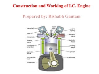
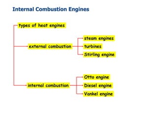
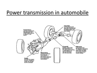
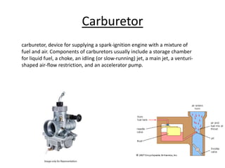
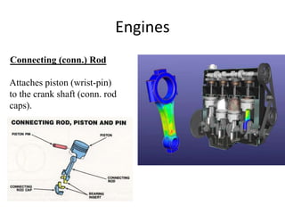
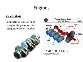
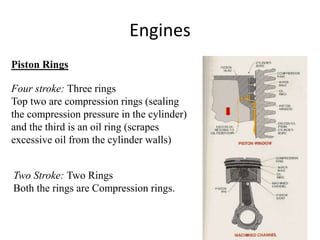
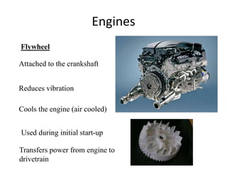
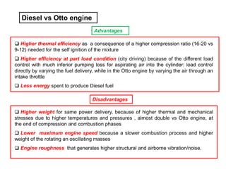
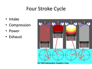
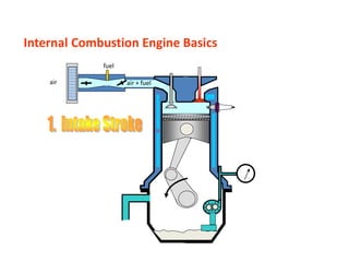
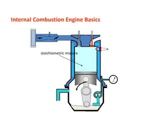
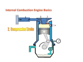
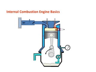
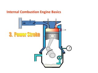
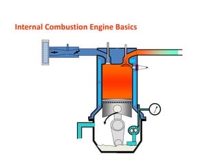
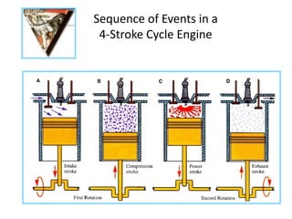
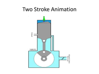
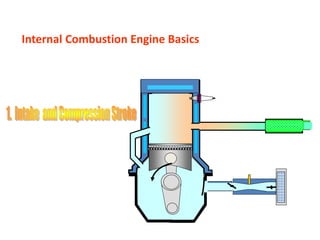
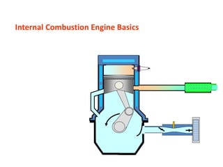
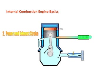
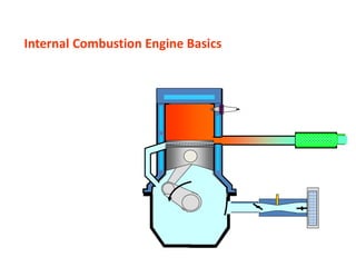
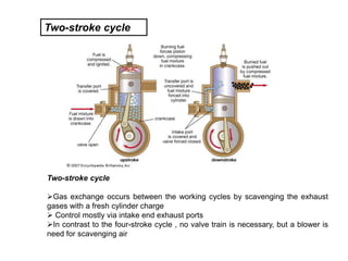
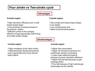
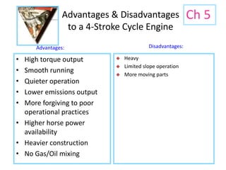
Construction and Working of I.C. Engine
Prepared by: Rishabh Gautam
Internal Combustion Engines
types of heat engines
external combustion
internal combustion
steam engines
turbines
Stirling engine
Otto engine
Diesel engine
Vankel engine
Power transmission in automobile
Carburetor
carburetor, device for supplying a spark-ignition engine with a mixture of
fuel and air. Components of carburetors usually include a storage chamber
for liquid fuel, a choke, an idling (or slow-running) jet, a main jet, a venturi-
shaped air-flow restriction, and an accelerator pump.
Slide 03
Internal Combustion Engine Basics
D. Abata
area
force
pressure =
force = pressure x area
Internal Combustion Engines
The internal combustion engine is
an engine in which the
combustion of fuel-oxidizer
mixture occurs in a confined space
applied in:
automotive
rail transportation
power generation
ships
aviation
garden appliances
Combustion Engine Definiton
Combustion engines are machines that deliver mechanical work
through a linked thermal and combustion process: mechanical work is
obtained from the chemical bound energy of the fuel (fuel energy)
through combustion by means of thermal energy.
In the reciprocating engines the working chamber has rigid walls: the
stroke of one of the these walls (pistons) provides a variable volume.
The work output is gained from the gas pressure
Engines
Configuration
• Engines: The cylinders
are arranged in a line, in a
single bank.
Engines
Parts
•Exhaust Valve lets the exhaust gases escape the combustion
Chamber. (Diameter is smaller then Intake valve)
•Intake Valve lets the air or air fuel mixture to enter the
combustion chamber. (Diameter is larger than the exhaust valve)
Valves: Minimum
Two Valves pre Cylinder
Engines
Cam Shaft: The shaft that has intake and
Exhaust cams for operating the valves.
Cam Lobe: Changes rotary motion
into reciprocating motion.
Engines
It provides the means of ignition when
the gasoline engine’s piston is at the end
of compression stroke, close to
Top Dead Center(TDC)
Spark Plug
The difference between a
"hot" and a "cold" spark
plug is that the ceramic tip
is longer on the
hotter plug.
Engines
Piston
A movable part fitted into a
cylinder, which can receive and
transmit power.
Through connecting rod, forces
the crank shaft to rotate.
Engines
Cylinder head
Part that covers and encloses the
Cylinder.
It contains cooling fins or water jackets
and the valves.
Some engines contains the cam shaft
in the cylinder head.
Engines
Engine Block
Foundation of the engine and
contains pistons, crank shaft,
cylinders, timing sprockets and
sometimes the cam shaft.
Engines
Connecting (conn.) Rod
Attaches piston (wrist-pin)
to the crank shaft (conn. rod
caps).
Engines
Crank Shaft
Converts up and down or
reciprocating motion into
circular or rotary motion.
DAMPNER PULLEY
Controls Vibration
Engines
Piston Rings
Four stroke: Three rings
Top two are compression rings (sealing
the compression pressure in the cylinder)
and the third is an oil ring (scrapes
excessive oil from the cylinder walls)
Two Stroke: Two Rings
Both the rings are Compression rings.
Engines
Flywheel
Attached to the crankshaft
Reduces vibration
Cools the engine (air cooled)
Used during initial start-up
Transfers power from engine to
drivetrain
Engines
20
Engine Related Terms
• TDC (top dead center)
• BDC (bottom dead center)
• Stroke
• Bore
• Revolution
• Compression Ratio
• Displacement
• Cycle
Nikolaus Otto was born in Holzhausen, Germany on 10th June 1832. In his
early years he began experimenting with gas engines and completed his first
atmospheric engine in 1867. In 1872 he joined with Gottlieb Daimler and
Wilhelm Maybach and in 1876 developed the first 4-stroke cycle internal
combustion engine based on principles patented in 1862 by Alphonse Beau
de Rochas. Although Otto's patent claim for the 'Otto Cycle' was invalidated
in 1886, his engineering work led to the first practical use of the 4-stroke
cycle which was to provide the driving force for transportation for over a
century. Nikolaus Otto died on 26th January 1891.
1
1
1






Four-stroke Otto cycle
Induction Stroke
The induction stroke is generally considered to be the
first stroke of the Otto 4-Stroke Cycle. At this point in
the cycle, the inlet valve is open and the exhaust valve
is closed. As the piston travels down the cylinder, a
new charge of fuel/air mixture is drawn through the
inlet port into the cylinder.
The adjacent figure shows the engine crankshaft
rotating in a clockwise direction. Fuel is injected
through a sequentially controlled port injector just
behind the inlet valve.
Compression Stroke
The compression stroke begins as the inlet valve
closes and the piston is driven upwards in the
cylinder bore by the momentum of the crankshaft
and flywheel.
Spark Ignition
Spark ignition is the point at which the spark is
generated at the sparking plug and is an essential
difference between the Otto and Diesel cycles. It may
also be considered as the beginning of the power
stroke. It is shown here to illustrate that due to flame
propagation delays, spark ignition timing commonly
takes place 10 degress before TDC during idle and will
advance to some 30 or so degrees under normal
running conditions.
Four-stroke Otto cycle
Power Stroke
The power stroke begins as the fuel/air mixture is ignited
by the spark. The rapidly burning mixture attempting to
expand within the cylinder walls, generates a high
pressure which forces the piston down the cylinder bore.
The linear motion of the piston is converted into rotary
motion through the crankshaft. The rotational energy is
imparted as momentum to the flywheel which not only
provides power for the end use, but also overcomes the
work of compression and mechanical losses incurred in
the cycle (valve opening and closing, alternator, fuel
pump, water pump, etc.).
Exhaust Stroke
The exhaust stroke is as critical to the smooth
and efficient operation of the engine as that of
induction. As the name suggests, it's the stroke
during which the gases formed during
combustion are ejected from the cylinder. This
needs to be as complete a process as possible,
as any remaining gases displace an equivalent
volume of the new charge of fuel/air mixture
and leads to a reduction in the maximum
possible power.
Exhaust and Inlet Valve Overlap
Exhaust and inlet valve overlap is the transition between the
exhaust and inlet strokes and is a practical necessity for the
efficient running of any internal combustion engine. Given the
constraints imposed by the operation of mechanical valves and
the inertia of the air in the inlet manifold, it is necessary to
begin opening the inlet valve before the piston reaches Top
Dead Centre (TDC) on the exhaust stroke. Likewise, in order to
effectively remove all of the combustion gases, the exhaust
valve remains open until after TDC. Thus, there is a point in
each full cycle when both exhaust and inlet valves are open.
The number of degrees over which this occurs and the
proportional split across TDC is very much dependent on the
engine design and the speed at which it operates.
Four-stroke Otto cycle
Rudolph Diesel was born in Paris of Bavarian parents in
1858. As a budding mechanical engineer at the Technical
University in Munich, he became fascinated by the 2nd law
of thermodynamics and the maximum efficiency of a Carnot
process and attempted to improve the existing thermal
engines of the day on the basis of purely theoretical
considerations. His first prototype engine was built in 1893,
a year after he applied for his initial patent, but it wasn't until
the third prototype was built in 1897 that theory was put into
practice with the first 'Diesel' engine.
Four-stroke Diesel cycle
Induction Stroke
The induction stroke in a Diesel engine is used to draw in
a new volume of charge air into the cylinder. As the
power generated in an engine is dependent on the
quantity of fuel burnt during combustion and that in turn
is determined by the volume of air (oxygen) present, most
diesel engines use turbochargers to force air into the
cylinder during the induction stroke.
Compression Stroke
The compression stroke begins as the inlet valve closes
and the piston is driven upwards in the cylinder bore by
the momentum of the crankshaft and flywheel.
The purpose of the compression stroke in a Diesel engine
is to raise the temperature of the charge air to the point
where fuel injected into the cylinder spontaneously ignites.
In this cycle, the separation of fuel from the charge air
eliminates problems with auto-ignition and therefore allows
Diesel engines to operate at much higher compression
ratios than those currently in production with the Otto
Cycle.
Compression Ignition
Compression ignition takes place when the fuel from
the high pressure fuel injector spontaneously ignites
in the cylinder.
In the theoretical cycle, fuel is injected at TDC, but as
there is a finite time for the fuel to ignite (ignition lag)
in practical engines, fuel is injected into the cylinder
before the piston reaches TDC to ensure that
maximum power can be achieved. This is synonymous
with automatic spark ignition advance used in Otto
cycle engines.
Four-stroke Diesel cycle
Power Stroke
The power stroke begins as the injected fuel
spontaneously ignites with the air in the cylinder. As
the rapidly burning mixture attempts to expand
within the cylinder walls, it generates a high pressure
which forces the piston down the cylinder bore. The
linear motion of the piston is converted into rotary
motion through the crankshaft. The rotational energy
is imparted as momentum to the flywheel which not
only provides power for the end use, but also
overcomes the work of compression and mechanical
losses incurred in the cycle (valve opening and
closing, alternator, fuel injector pump, water pump,
etc.).
Exhaust Stroke
The exhaust stroke is as critical to the smooth and
efficient operation of the engine as that of induction.
As the name suggests, it's the stroke during which the
gases formed during combustion are ejected from the
cylinder. This needs to be as complete a process as
possible, as any remaining gases displace an
equivalent volume of the new charge air and leads to a
reduction in the maximum possible power.
Exhaust and Inlet Valve Overlap
Exhaust and inlet valve overlap is the transition between
the exhaust and inlet strokes and is a practical necessity
for the efficient running of any internal combustion
engine. Given the constraints imposed by the operation
of mechanical valves and the inertia of the air in the inlet
manifold, it is necessary to begin opening the inlet valve
before the piston reaches Top Dead Centre (TDC) on the
exhaust stroke. Likewise, in order to effectively remove
all of the combustion gases, the exhaust valve remains
open until after TDC. Thus, there is a point in each full
cycle when both exhaust and inlet valves are open. The
number of degrees over which this occurs and the
proportional split across TDC is very much dependent on
the engine design and the speed at which it operates.
Four-stroke Diesel cycle
Diesel vs Otto engine
 Higher thermal efficiency as a consequence of a higher compression ratio (16-20 vs
9-12) needed for the self ignition of the mixture
 Higher efficiency at part load condition (city driving) because of the different load
control with much inferior pumping loss for aspirating air into the cylinder: load control
directly by varying the fuel delivery, while in the Otto engine by varying the air through an
intake throttle
 Less energy spent to produce Diesel fuel
 Higher weight for same power delivery, because of higher thermal and mechanical
stresses due to higher temperatures and pressures , almost double vs Otto engine, at
the end of compression and combustion phases
 Lower maximum engine speed because a slower combustion process and higher
weight of the rotating an oscillating masses
 Engine roughness that generates higher structural and airborne vibration/noise.
Advantages
Disadvantages
Four Stroke Cycle
• Intake
• Compression
• Power
• Exhaust
Internal Combustion Engine Basics
fuel
air air + fuel
Internal Combustion Engine Basics
stoichiometric mixture
Internal Combustion Engine Basics
Sequence of Events in a
4-Stroke Cycle Engine
Two Stroke Animation
Internal Combustion Engine Basics
Two-stroke cycle
Gas exchange occurs between the working cycles by scavenging the exhaust
gases with a fresh cylinder charge
 Control mostly via intake end exhaust ports
In contrast to the four-stroke cycle , no valve train is necessary, but a blower is
need for scavenging air
Two-stroke cycle
4-stroke engine
High volumetric efficiency over a wide
engine speed range
Low sensitivity to pressure losses in
the exhaust system
Effective control of the charging
efficiency trough appropriate valve timing
and intake system design
2-stroke engine
Very simple and cheap engine design
Low weight
Low manufacturing cost
Better torsional forces pattern
2-stroke engine
Higher fuel consumption
Higher HC emissions because of a
problematic cylinder scavenging
Lower mean effective pressure
because of poorer volumetric efficiency
Higher thermal load because no gas
echange stroke
Poor idle because of high residual gas
percentage into the cylinder
4-stroke engine
High complexity of the valve control
Reduced power density because the
work is generated only every second
shaft rotation
Four stroke vs Two-stroke cycle
Advantages
Disadvantages
Advantages & Disadvantages
to a 4-Stroke Cycle Engine
Ch 5
• High torque output
• Smooth running
• Quieter operation
• Lower emissions output
• More forgiving to poor
operational practices
• Higher horse power
availability
• Heavier construction
• No Gas/Oil mixing
Advantages: Disadvantages:
 Heavy
 Limited slope operation
 More moving parts

ic engine for mechanical student with full

  • 1.
    Construction and Workingof I.C. Engine Prepared by: Rishabh Gautam
  • 2.
    Internal Combustion Engines typesof heat engines external combustion internal combustion steam engines turbines Stirling engine Otto engine Diesel engine Vankel engine
  • 3.
  • 4.
    Carburetor carburetor, device forsupplying a spark-ignition engine with a mixture of fuel and air. Components of carburetors usually include a storage chamber for liquid fuel, a choke, an idling (or slow-running) jet, a main jet, a venturi- shaped air-flow restriction, and an accelerator pump.
  • 5.
    Slide 03 Internal CombustionEngine Basics D. Abata area force pressure = force = pressure x area
  • 6.
    Internal Combustion Engines Theinternal combustion engine is an engine in which the combustion of fuel-oxidizer mixture occurs in a confined space applied in: automotive rail transportation power generation ships aviation garden appliances
  • 7.
    Combustion Engine Definiton Combustionengines are machines that deliver mechanical work through a linked thermal and combustion process: mechanical work is obtained from the chemical bound energy of the fuel (fuel energy) through combustion by means of thermal energy. In the reciprocating engines the working chamber has rigid walls: the stroke of one of the these walls (pistons) provides a variable volume. The work output is gained from the gas pressure
  • 8.
    Engines Configuration • Engines: Thecylinders are arranged in a line, in a single bank.
  • 9.
    Engines Parts •Exhaust Valve letsthe exhaust gases escape the combustion Chamber. (Diameter is smaller then Intake valve) •Intake Valve lets the air or air fuel mixture to enter the combustion chamber. (Diameter is larger than the exhaust valve) Valves: Minimum Two Valves pre Cylinder
  • 10.
    Engines Cam Shaft: Theshaft that has intake and Exhaust cams for operating the valves. Cam Lobe: Changes rotary motion into reciprocating motion.
  • 11.
    Engines It provides themeans of ignition when the gasoline engine’s piston is at the end of compression stroke, close to Top Dead Center(TDC) Spark Plug The difference between a "hot" and a "cold" spark plug is that the ceramic tip is longer on the hotter plug.
  • 12.
    Engines Piston A movable partfitted into a cylinder, which can receive and transmit power. Through connecting rod, forces the crank shaft to rotate.
  • 13.
    Engines Cylinder head Part thatcovers and encloses the Cylinder. It contains cooling fins or water jackets and the valves. Some engines contains the cam shaft in the cylinder head.
  • 14.
    Engines Engine Block Foundation ofthe engine and contains pistons, crank shaft, cylinders, timing sprockets and sometimes the cam shaft.
  • 15.
    Engines Connecting (conn.) Rod Attachespiston (wrist-pin) to the crank shaft (conn. rod caps).
  • 16.
    Engines Crank Shaft Converts upand down or reciprocating motion into circular or rotary motion. DAMPNER PULLEY Controls Vibration
  • 17.
    Engines Piston Rings Four stroke:Three rings Top two are compression rings (sealing the compression pressure in the cylinder) and the third is an oil ring (scrapes excessive oil from the cylinder walls) Two Stroke: Two Rings Both the rings are Compression rings.
  • 18.
    Engines Flywheel Attached to thecrankshaft Reduces vibration Cools the engine (air cooled) Used during initial start-up Transfers power from engine to drivetrain
  • 19.
  • 20.
    20 Engine Related Terms •TDC (top dead center) • BDC (bottom dead center) • Stroke • Bore • Revolution • Compression Ratio • Displacement • Cycle
  • 21.
    Nikolaus Otto wasborn in Holzhausen, Germany on 10th June 1832. In his early years he began experimenting with gas engines and completed his first atmospheric engine in 1867. In 1872 he joined with Gottlieb Daimler and Wilhelm Maybach and in 1876 developed the first 4-stroke cycle internal combustion engine based on principles patented in 1862 by Alphonse Beau de Rochas. Although Otto's patent claim for the 'Otto Cycle' was invalidated in 1886, his engineering work led to the first practical use of the 4-stroke cycle which was to provide the driving force for transportation for over a century. Nikolaus Otto died on 26th January 1891. 1 1 1       Four-stroke Otto cycle
  • 22.
    Induction Stroke The inductionstroke is generally considered to be the first stroke of the Otto 4-Stroke Cycle. At this point in the cycle, the inlet valve is open and the exhaust valve is closed. As the piston travels down the cylinder, a new charge of fuel/air mixture is drawn through the inlet port into the cylinder. The adjacent figure shows the engine crankshaft rotating in a clockwise direction. Fuel is injected through a sequentially controlled port injector just behind the inlet valve. Compression Stroke The compression stroke begins as the inlet valve closes and the piston is driven upwards in the cylinder bore by the momentum of the crankshaft and flywheel. Spark Ignition Spark ignition is the point at which the spark is generated at the sparking plug and is an essential difference between the Otto and Diesel cycles. It may also be considered as the beginning of the power stroke. It is shown here to illustrate that due to flame propagation delays, spark ignition timing commonly takes place 10 degress before TDC during idle and will advance to some 30 or so degrees under normal running conditions. Four-stroke Otto cycle
  • 23.
    Power Stroke The powerstroke begins as the fuel/air mixture is ignited by the spark. The rapidly burning mixture attempting to expand within the cylinder walls, generates a high pressure which forces the piston down the cylinder bore. The linear motion of the piston is converted into rotary motion through the crankshaft. The rotational energy is imparted as momentum to the flywheel which not only provides power for the end use, but also overcomes the work of compression and mechanical losses incurred in the cycle (valve opening and closing, alternator, fuel pump, water pump, etc.). Exhaust Stroke The exhaust stroke is as critical to the smooth and efficient operation of the engine as that of induction. As the name suggests, it's the stroke during which the gases formed during combustion are ejected from the cylinder. This needs to be as complete a process as possible, as any remaining gases displace an equivalent volume of the new charge of fuel/air mixture and leads to a reduction in the maximum possible power. Exhaust and Inlet Valve Overlap Exhaust and inlet valve overlap is the transition between the exhaust and inlet strokes and is a practical necessity for the efficient running of any internal combustion engine. Given the constraints imposed by the operation of mechanical valves and the inertia of the air in the inlet manifold, it is necessary to begin opening the inlet valve before the piston reaches Top Dead Centre (TDC) on the exhaust stroke. Likewise, in order to effectively remove all of the combustion gases, the exhaust valve remains open until after TDC. Thus, there is a point in each full cycle when both exhaust and inlet valves are open. The number of degrees over which this occurs and the proportional split across TDC is very much dependent on the engine design and the speed at which it operates. Four-stroke Otto cycle
  • 24.
    Rudolph Diesel wasborn in Paris of Bavarian parents in 1858. As a budding mechanical engineer at the Technical University in Munich, he became fascinated by the 2nd law of thermodynamics and the maximum efficiency of a Carnot process and attempted to improve the existing thermal engines of the day on the basis of purely theoretical considerations. His first prototype engine was built in 1893, a year after he applied for his initial patent, but it wasn't until the third prototype was built in 1897 that theory was put into practice with the first 'Diesel' engine. Four-stroke Diesel cycle
  • 25.
    Induction Stroke The inductionstroke in a Diesel engine is used to draw in a new volume of charge air into the cylinder. As the power generated in an engine is dependent on the quantity of fuel burnt during combustion and that in turn is determined by the volume of air (oxygen) present, most diesel engines use turbochargers to force air into the cylinder during the induction stroke. Compression Stroke The compression stroke begins as the inlet valve closes and the piston is driven upwards in the cylinder bore by the momentum of the crankshaft and flywheel. The purpose of the compression stroke in a Diesel engine is to raise the temperature of the charge air to the point where fuel injected into the cylinder spontaneously ignites. In this cycle, the separation of fuel from the charge air eliminates problems with auto-ignition and therefore allows Diesel engines to operate at much higher compression ratios than those currently in production with the Otto Cycle. Compression Ignition Compression ignition takes place when the fuel from the high pressure fuel injector spontaneously ignites in the cylinder. In the theoretical cycle, fuel is injected at TDC, but as there is a finite time for the fuel to ignite (ignition lag) in practical engines, fuel is injected into the cylinder before the piston reaches TDC to ensure that maximum power can be achieved. This is synonymous with automatic spark ignition advance used in Otto cycle engines. Four-stroke Diesel cycle
  • 26.
    Power Stroke The powerstroke begins as the injected fuel spontaneously ignites with the air in the cylinder. As the rapidly burning mixture attempts to expand within the cylinder walls, it generates a high pressure which forces the piston down the cylinder bore. The linear motion of the piston is converted into rotary motion through the crankshaft. The rotational energy is imparted as momentum to the flywheel which not only provides power for the end use, but also overcomes the work of compression and mechanical losses incurred in the cycle (valve opening and closing, alternator, fuel injector pump, water pump, etc.). Exhaust Stroke The exhaust stroke is as critical to the smooth and efficient operation of the engine as that of induction. As the name suggests, it's the stroke during which the gases formed during combustion are ejected from the cylinder. This needs to be as complete a process as possible, as any remaining gases displace an equivalent volume of the new charge air and leads to a reduction in the maximum possible power. Exhaust and Inlet Valve Overlap Exhaust and inlet valve overlap is the transition between the exhaust and inlet strokes and is a practical necessity for the efficient running of any internal combustion engine. Given the constraints imposed by the operation of mechanical valves and the inertia of the air in the inlet manifold, it is necessary to begin opening the inlet valve before the piston reaches Top Dead Centre (TDC) on the exhaust stroke. Likewise, in order to effectively remove all of the combustion gases, the exhaust valve remains open until after TDC. Thus, there is a point in each full cycle when both exhaust and inlet valves are open. The number of degrees over which this occurs and the proportional split across TDC is very much dependent on the engine design and the speed at which it operates. Four-stroke Diesel cycle
  • 27.
    Diesel vs Ottoengine  Higher thermal efficiency as a consequence of a higher compression ratio (16-20 vs 9-12) needed for the self ignition of the mixture  Higher efficiency at part load condition (city driving) because of the different load control with much inferior pumping loss for aspirating air into the cylinder: load control directly by varying the fuel delivery, while in the Otto engine by varying the air through an intake throttle  Less energy spent to produce Diesel fuel  Higher weight for same power delivery, because of higher thermal and mechanical stresses due to higher temperatures and pressures , almost double vs Otto engine, at the end of compression and combustion phases  Lower maximum engine speed because a slower combustion process and higher weight of the rotating an oscillating masses  Engine roughness that generates higher structural and airborne vibration/noise. Advantages Disadvantages
  • 28.
    Four Stroke Cycle •Intake • Compression • Power • Exhaust
  • 29.
    Internal Combustion EngineBasics fuel air air + fuel
  • 30.
    Internal Combustion EngineBasics stoichiometric mixture
  • 31.
  • 32.
  • 33.
  • 34.
  • 35.
  • 36.
    Sequence of Eventsin a 4-Stroke Cycle Engine
  • 37.
  • 38.
  • 39.
  • 40.
  • 41.
  • 42.
    Two-stroke cycle Gas exchangeoccurs between the working cycles by scavenging the exhaust gases with a fresh cylinder charge  Control mostly via intake end exhaust ports In contrast to the four-stroke cycle , no valve train is necessary, but a blower is need for scavenging air Two-stroke cycle
  • 43.
    4-stroke engine High volumetricefficiency over a wide engine speed range Low sensitivity to pressure losses in the exhaust system Effective control of the charging efficiency trough appropriate valve timing and intake system design 2-stroke engine Very simple and cheap engine design Low weight Low manufacturing cost Better torsional forces pattern 2-stroke engine Higher fuel consumption Higher HC emissions because of a problematic cylinder scavenging Lower mean effective pressure because of poorer volumetric efficiency Higher thermal load because no gas echange stroke Poor idle because of high residual gas percentage into the cylinder 4-stroke engine High complexity of the valve control Reduced power density because the work is generated only every second shaft rotation Four stroke vs Two-stroke cycle Advantages Disadvantages
  • 44.
    Advantages & Disadvantages toa 4-Stroke Cycle Engine Ch 5 • High torque output • Smooth running • Quieter operation • Lower emissions output • More forgiving to poor operational practices • Higher horse power availability • Heavier construction • No Gas/Oil mixing Advantages: Disadvantages:  Heavy  Limited slope operation  More moving parts