1. CEng 5331 2013E.c
Structural Design Final Exam Solutions set by MGA Page 1
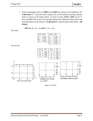
1. Lateral Earthquake forces of 290kN and 316kN are acting on the building in the
X-direction at 1st
and roof floors respectively, on the moment resisting concrete
frame as shown in the Figure below. If center of mass (4.391, 3.491) on the 1st
floor and (3.5, 5.7) on the roof provided respectively, determine direct shear and
corrected shears on the frames in X-direction by using the given data below. (20
Points)
(Hint use, ̅ ̅ )
First story
Second story
Figure 1 For Q#1
Axis Dx Axis Dy
C 146 1 148
B 172 2 172
A 169 3 164
4 156
Axis Dx Axis Dy
C 128 1 136
B 140 2 142
A 122 3 126
4 140
2. CEng 5331 2013E.c
Structural Design Final Exam Solutions set by MGA Page 2
Solutions
Given
Horizontal lateral force of , 290kN on 1st
floor
Horizontal lateral force of, 316kN on the roof or 2nd
floor
Center of mass (4.391, 3.491) on the 1st
floor
Center of mass (3.5, 5.7) on the roof or 2nd
floor
D-values
On the 1st
floor
First story
Second story
Solutions
For 1st
story
Axis Qy xi Dy*xi
1 148 0 0
2 172 3 516
3 164 6.5 1066
4 156 9.5 1482
sum 640 3064
xs 4.788
Axis Dx Axis Dy
C 146 1 148
B 172 2 172
A 169 3 164
4 156
Axis Dx Axis Dy
C 128 1 136
B 140 2 142
A 122 3 126
4 140
3. CEng 5331 2013E.c
Structural Design Final Exam Solutions set by MGA Page 3
Axis Dx yi Dx*yi
C 146 0 0
B 172 3 516
A 169 7 1183
487 1699
ys 3.489
∑
∑
∑
∑
Determination of eccentricity
1st
floor
Normal eccentricity
Additional eccentricity
4. CEng 5331 2013E.c
Structural Design Final Exam Solutions set by MGA Page 4
Design eccentricity
Center of stiffness (
1st
floor direct shear, ∑
`Axis Dx Qx(kN) Qi(kN)
C 148
290
89.417
B 165 99.688
A 167 100.896
480
Since there is an eccentricity between the center of rigidity and center of mass , direct shear must
be corrected so that the torsional effect is considered.
∑ ̅ ∑ ̅
∑ ̅ ∑ ̅
∑ ̅ ∑ ∑
∑ ̅ ∑ ∑
Where ̅ ̅ where ( )
5. CEng 5331 2013E.c
Structural Design Final Exam Solutions set by MGA Page 5
Analysis of rotational moment of inertia
Axis ̅ ̅ ̅
1 148 0.000 -3.467 12.020 1778.973
2 172 3.000 -0.467 0.218 37.511
3 164 6.500 3.033 9.199 1508.651
4 156 9.500 6.033 36.397 5677.946
Sum 640 9003.081
Axis ̅ ̅ ̅
C 146 0 -4.788 22.925 3347.042
B 172 3 -1.788 3.197 549.8744
A 169 7 2.212 4.893 826.9075
Sum 487 4723.824
The center of mass is above the center of stiffness, taking the point of reference at center of
stiffness makes design eccentricity positive
Analysis of correction factor
The direction of the lateral load is in x so use
6. CEng 5331 2013E.c
Structural Design Final Exam Solutions set by MGA Page 6
For
∑ ̅ ∑ ̅
The D-value of every axis is various, should also be various
∑ ̅ ∑ ̅
∑ ̅ ∑ ̅
∑ ̅ ∑ ̅
For
Since the point of reference is at center of stiffness take as positive
∑ ̅ ∑ ̅
∑ ̅ ∑ ̅
∑ ̅ ∑ ̅
∑ ̅ ∑ ̅
Since the direction of earth quake is in x- direction, correction factor is applied
Take, maximum
Axis Qi (kN) ̅ Fi (kN)
C 86.940 146 -4.788 0.982 0.981 0.983 85.400
B 102.423 172 -1.788 1.008 0.993 1.008 103.222
A 100.637 169 2.212 0.991 1.008 1.008 101.470
290.000 487 290.091
7. CEng 5331 2013E.c
Structural Design Final Exam Solutions set by MGA Page 7
For 2nd
Story
D-Value
Direct shear analysis, ∑
Axis Dx QX (kN) Qi(kN)
C 128 316 103.7128
B 140 316 113.4359
A 122 316 98.85128
Sum 390 Sum 316
Center of stiffness analysis
Axis Dy xi Dy*xi
1 136 0 0
2 142 3 426
3 126 6.5 819
4 140 9.5 1330
sum 544 2575
xs 4.733
Axis Dx yi Dx* yi
c 128 0 0
b 140 3 420
a 122 7 854
390 1274
ys 3.267
∑
∑
∑
∑
Axis Dx Axis Dy
C 128 1 136
B 140 2 142
A 122 3 126
4 140
8. CEng 5331 2013E.c
Structural Design Final Exam Solutions set by MGA Page 8
Analysis of rotational moment of inertia
Axis ̅ ̅ ̅
1 146 0.000 -4.733 22.406 3047.162
2 142 3.000 -1.733 3.005 426.691
3 126 6.500 1.767 3.121 393.205
4 140 9.500 4.767 22.720 3180.792
Sum 544 7047.851
Axis ̅ ̅ ̅
C 128 0 -3.267 10.671 1365.902
B 140 3 -0.267 0.071 9.956
A 122 7 3.733 13.938 1700.409
Sum 390 3076.267
The center of mass is above the center of stiffness, taking the point of reference at center of
stiffness makes design eccentricity positive, which is similar to 1st
floor
Determination of eccentricity
2nd
floor or roof
Normal eccentricity
Additional eccentricity
9. CEng 5331 2013E.c
Structural Design Final Exam Solutions set by MGA Page 9
Design eccentricity
Analysis of correction factor
The direction of the lateral load is in x so use
For
∑ ̅ ∑ ̅
Since the point of reference is at center of stiffness take as positive
The D-value of every axis is various should also be various
∑ ̅ ∑ ̅
∑ ̅ ∑ ̅
∑ ̅ ∑ ̅
10. CEng 5331 2013E.c
Structural Design Final Exam Solutions set by MGA Page 10
For
Since the point of reference is at center of stiffness take as positive
∑ ̅ ∑ ̅
∑ ̅ ∑ ̅
∑ ̅ ∑ ̅
∑ ̅ ∑ ̅
Since the direction of earth quake is in x- direction, correction factor is applied.
Take, maximum,
Axis Qi ̅ Fi (kN)
C 103.713 128.000 -3.267 0.914 0.885 0.914 94.789
B 113.436 140.000 -0.267 0.992 0.990 0.992 112.564
A 98.851 122.000 3.733 1.094 1.125 1.125 111.229
316.000 390.000 318.583
11. CEng 5331 2013E.c
Structural Design Final Exam Solutions set by MGA Page 11
2. Determine the story shear distribution for the shear wall system shown in the
Figure below if the total story shear applied is 120kN. Assume center of mass to
be located at ( ) and use the thickness of all shear
walls as 200mm
Solution
Step1: Determination of center of stiffness
The geometric centroids, moment of inertias and other required parameters for each wall can be
summarized as shown in the table blow.
̅ ̅ ̅ ̅
̅
̅
̅
̅
A 0.1 10 1.066667 0 0.106667 0 7.4 -2.05 58.41067 0
B 7.5 11.9 0 2.08333 0 24.7917 0 -3.95 0 32.5052
C 7.5 4 0 2.083333 0 8.33333 0 3.95 0 32.50521
D 14.9 2 1.066667 0 15.89333 0 -7.4 5.95 58.41067 0
sum 2.13333 4.16667 16 33.125 116.8213 65.01042
∑
∑
∑
∑
∑ ̅ ̅ 181.83175
12. CEng 5331 2013E.c
Structural Design Final Exam Solutions set by MGA Page 12
Step 2: Calculation of eccentricity and torsion of the applied horizontal force
Assume center of mass to be located at ( ) from the reference
point
Therefor:-
Step 3: distribution of story shear to walls
Distribution of story shear in each wall when the earthquake force is in the x-direction
∑
̅
∑ ̅ ̅
̅ ̅ ̅ ̅
̅̅̅
1 1.066667 0 7.4 -2.05 58.4107 0
120 120
0
2 0 2.0833 0 -3.95 0 32.5052 54.56916
3 0 2.0833 0 3.95 0 32.5052 65.43084
4 1.066667 0 -7.4 5.95 58.4107 0 0
summation 2.133333 4.167 116.821 65.0104
Distribution of story shear in each wall when the earthquake force is in the y-direction
∑
̅̅̅
∑ ̅ ̅
̅ ̅ ̅ ̅
̅̅̅
1 1.0667 0 7.4 -2.05 58.4107 0
120 168
67.2929
2 0 2.0833 0 -3.95 0 32.5052 0
3 0 2.0833 0 3.95 0 32.5052 0
4 1.0667 0 -7.4 5.95 58.4107 0 52.7071
summation 2.1333 4.1667 116.821 65.0104
13. CEng 5331 2013E.c
Structural Design Final Exam Solutions set by MGA Page 13
3. Select one of the following slab panels that are shown in the Figure below and
determine design moments at critical sections by using strip method. If the slab is
exposed to unfactored LL = 5kN/m2
and dead load of slab itself. If the unit weight
of cement screed and concrete are 19kN/m3
and 25kN/m3
respectively. Use
thickness of cement screed 3cm and over all depth of slab, D = H = 230mm.
Assume any missed data reasonably.
(10 Points)
Figure 3 for Q#3