SlideShare a Scribd company logo
1 of 55
Download to read offline
1
Get Started MicroPython ESP32
Introduction
The Makerfabs MakePython ESP32 Kit intended to help learners getting started with MicroPython on the
ESP32. This Kits includes the most common electronic components and modules, for the starters to learn
the basic knowledge of MicroPython and usage of uPyCraft IDE. 12 basic lessons help starters to learn
the usage and program skills about MicroPython.
The total learning time for this kits& lessons is about 20 hours.
What is MicroPython?
Python is one of the most widely use simple and easy-to-learn programming languages around.
MicroPython is a lean implementation of the Python 3 programming language that has been pared down
to run efficiently on microcontrollers. It is a relatively simple but powerful language that is easy for
beginners to pick up and has been gaining popularity in schools as an introductory language.
MicroPython has nearly all of the features of Python, which means that interacting with hardware is now
easily accessible to beginners and seasoned Python programmers alike.
MicroPython goal is to make programming digital electronic as simple as possible, so it can be used by
anyone. Currently, MicroPython is used by hobbyists, researchers, teachers, educators, and even in
commercial products.
Product List:
2
Makerfabs MakePython ESP32 Pin figure:
3
Directory
Introduction........................................................................................................................................1
What is MicroPython?..................................................................................................................1
Product List....................................................................................................................................1
Makerfabs MakePython ESP32 Pin figure...............................................................................2
I.MicroPython Development Tool.................................................................................................. 3
II.MakePython Lessons...................................................................................................................9
1.Lesson1 LED Control............................................................................................................... 9
2.Lesson2 Running LED...........................................................................................................11
3.Lesson3 Button....................................................................................................................... 13
4.Lesson4 PWM Control...........................................................................................................15
5.Lesson5 Voice Control...........................................................................................................18
6.Lesson6 OLED Display..........................................................................................................21
7.Lesson7 Temperature Monitor DS18B20...........................................................................23
8.Lesson8 Digital LED WS2812.............................................................................................. 25
9.Lesson9 Pulse Sensor...........................................................................................................28
10.Lesson10 AnalogRead........................................................................................................ 30
11.Lesson11 Ultrasonic Ranging............................................................................................ 33
12.Lesson12 WiFi...................................................................................................................... 37
III.Troubleshooting......................................................................................................................... 48
IV.Flash/Upload MicroPython Firmware to ESP32.................................................................. 50
I. MicroPython Development Tool
Installing uPyCraft IDE Windows PC
There many codes& programming methods with MicroPython. For this tutorial, we use uPyCraft IDE,
which is the most simple& easy way for starts to skip into MicroPython. You can learn more about
uPyCraft IDE on their GitHub repository or explore the uPyCraft IDE source code. Click this link to
download uPyCraft IDE for Windows: https://randomnerdtutorials.com/uPyCraftWindows.
After a few seconds you should see a similar file (uPyCraft_VX.exe) in your Downloads folder
4
Double-click that file. A new window opens with the uPyCraft IDE software.
A Simple code for blinking an LED on ESP32 as follows:
Get Start with uPyCraft IDE
Open uPyCraft IDE. Let’s take a closer look at each section of uPyCraft IDE:
1->Folder and files
2->Editor
3->MicroPython Shell/Terminal
4->Tools
a. Folder and files
This section shows several folders and files. The device folder shows the files that are currently stored on
your ESP board. If you have your ESP32 connected via serial to uPyCraft IDE, when you expand the
device folder, all files stored should load. By default, you should only have a boot.py file. To run your main
5
code, it is recommended to create a main.py file.
 boot.py: runs when the device starts and sets up several configuration options;
 main.py: this is the main script that contains your code. It is executed immediately after the boot.py.
The sd folder is meant to access files stored on SD cards this is only works with boards like the PyBoard
that come with an SD card slot.
The uPy_lib shows the built-in IDE library files.
The workspace is a directory to save your files. These files are saved in your computer in a directory
defined by you. This is a special useful to keep all your files organized at hand.
When using uPyCraft for the first time, to select your working directory, click the workspace folder. A new
window pops up for you to choose your workspace path. Create a new folder or select an existing folder
to be your working directory.
Then, go to File > Reflush Directory to update the directory.
*Note: to change your user directory, simply go to Tools >InitConfig and click the workspace directory
folder to choose a different path.
b. Editor
The Editor section is where you write your code and edit your .py files. You can open more than one file,
and the Editor will open a new tab for each file.
c. MicroPython Shell/terminal
On the MicroPython Shell you can type commands to be executed immediately by your ESP board
without the need of uploading new files. The terminal also provides information about the state of an
executing program, shows errors related with upload, syntax errors, prints messages, etc…
d. Tools
The icons placed at the rightmost side allow you to quickly perform tasks. Each button is labeled in the
figure below:
 New file: creates a new file on the Editor;
 Open file: open a file from your computer;
 Save file: saves a file;
 Download and run: upload the code to your board and execute the code;
6
 Stop: stop the execution of the code – it’s the same as entering CRTL+C on the Shell to stop all
scripts from running;
 Connect/Disconnect: connect or disconnect to your board via Serial. You must select the serial
port first in Tools > Serial;
 Undo: undo last change in the code Editor;
 Redo: redo last change in the code Editor;
 Syntax check: checks the syntax of your code;
 Clear: clear the Shell/terminal window messages.
Establishing a communication with the board
After having the MicroPython firmware installed (MicroPython Firmware already installed when you get
Makerfabs MakePython ESP32), connect it to your computer through an USB cable, follow the steps:
1. Tools > Board and select the board you’re using. Select the esp32
2. Go to Tools > Serial and select the com port your ESP is connected to(download the USB driver at:
https://www.silabs.com/products/development-tools/software/usb-to-uart-bridge-vcp-drivers)
3. Press the Connect button to establish a serial communication with your board.
You will see “>>> “ appear in the Shell window after a successful connection with your board. You can
type the print command to test if it’s working. Try to print:
>>>print(“hello, world”)
It should print the “Hello,World” message. Only if you see that message, you can continue with this
tutorial. Otherwise, make sure you have established a serial communication with your board or that
you’ve flashed successfully the MicroPython firmware on your board.
Creating the main.py file on your board
1. Press the “New file” button to create a new file.
2. Press the “Save file” button to save the file in your computer.
3. A new window opens, name your file main.py and save it in your computer:
7
4. After that, you should see the following in your uPyCraft IDE (the boot.py file in your device and a new
tab with the main.py file):
5. Click the “Download and run” button to upload the file to your ESP board
6. The device directory should now load the main.py file. Your ESP has the file main.py stored.
Uploading the first Script: Blinking LED
Ok, so let’s begin to try to upload a very basic LED blink script into MakePython ESP32 board.
1. Copy the following code to the Editor on the main.py file:
8
From machine import Pin
From time import sleep
Led = Pin(2, Pin.OUT)
while True:
Led.value(not led.value())
sleep(0.5)
2. Press the “Stop” button to stop any script from running in your board
3. Click the “Download and Run button” to upload the script to the ESP32.
4. You should see a message saying “download ok” in the Shell window, it means that the updates
succeed.
To run the script that was just uploaded to your board, you need to press the “Stop” button, then press
the on-board ESP32 RST (RESET) button to restart your board and run the script from the start.
If you want to run the program on power, you can write code in the main.py file
* Note that when there much files in your MakePython boards, it is suggested to delete un-necessary files. Right click the file
and select the “delete” to delete these files.
9
II. MakePython Lessons
1. Lesson1: LED Control
This is the most basic lesson, in which we will learn how to control the digital output pins with
MicroPython, by control the lighting of an LED.
Material:
 1*LED;
 Resistor: 1*330R;
 Jump wires;
Instructions: The short pin on the left is negative and the long pin on the right is positive.
The purpose of resistor is to limit the current, avoid burning LED lamp with too much current.
Wiring: Connect the long LED pin to the end of the 330R resistor, the other end of the resistance is
connected to 3.3v, the short pin of the LED lamp is connected to the IO5 of ESP32. As follows:
Create a file:Open the uPyCraft IDE by clicking , and click save ,to name the Settings file, select
your own save path. You can then program in the LED documentation:
*Note: The first time you open the uPyCraft IDE, the workSpace path does not exist. When you click, the workSpace dialog
box will pop up. You can create a workSpace directory to store the user's files by selecting the directory you want to store.
10
Code and comments:
import time #use the time class
from machine import Pin #use the machine.Pin class
led=Pin(5,Pin.OUT) #create LED object from pin5,Set Pin5 to output
try:
while True: #repeat the following code
led.value(1) #turn off (Set high level)
time.sleep(0.5) #waiting for 0.5 seconds
led.value(0) #turn on (Set low level)
time.sleep(0.5) #waiting for 0.5 seconds
except KeyboardInterrupt:
pass
Grammar explanation:
 led=Pin(5,Pin.OUT):
Create an LED object and set it to output mode
 while:
Used to loop through a program, that is, under certain conditions, loop through a segment of a program to
handle the same task that needs to be processed repeatedly
 led.value(1):
Set the led pin value to high level. Since the other pin is connected to 3.3v, there is no voltage difference
between the two pins.
 led.value(0):
Set the pin value to low level, there is a voltage difference between two pins, there is a current through,
the LED light is on.
 time.sleep(0.5):
Delay 0.5 seconds, in this time the control will be sleep and do nothing.
The experimental results:
Click the to save and the to run, you will see the LED lights blinks with interval of 0.5 seconds.
You can try changing it to other pins yourself. For example, change to led=Pin(4,Pin.OUT) , then connect
the wire to IO4, and the light will flash, or the delay is changed to time.sleep(1),The light flickers slowly,
with interval of1s. You can also try to increase the number of LED lights and keep them on and off.
Extension:
You can also control the LED lighting by sending command through serial port.
*Note: If your lights are still flashing, that means the code is still running, press to stop the program running. Write
the code after ">>>" and press enter after each line:
11
code:
>>>from machine import Pin #Press enter to jump the cursor to the next line
>>>led=Pin(5,Pin.OUT)
>>>led.value(1) #Press enter, led off
>>>led.value(0) #Press enter, led on
* Each time you finish writing the code, you need to press enter and move the cursor to the next line behind “>>>”
2. Lesson2: Running LED
In this experiment, multiple LED lights are controlled to deepen the understanding of board GPIO port,
compilation environment and program framework.
Material:
 4*LEDs;
 resistance:4*330R;
12
 Jump wires;
Schematic:
Wiring: Connect the short LED pin to the IO15, IO14, IO13 and IO12 of ESP32, and connect the long pin
to one end of the 330R resistor and the other end of the resistor to 3.3V:
Create a new running_LED file with the following code and comments:
from machine import Pin
import time
#Create an array of Pin15,Pin14,Pin13,Pin12 leds
leds = [Pin(15,Pin.OUT),Pin(14,Pin.OUT),Pin(13,Pin.OUT),Pin(12,Pin.OUT)]
n=0
try:
while True:
n = (n+1)%4 #The remainder sign % guarantees that n is between 0 and 3
leds[n].value(1) #The value of the NTH LED is high level,turn off
time.sleep_ms(30) #Delay of 30 milliseconds
leds[n].value(0) #The value of the NTH LED is low level,turn on
time.sleep_ms(30) #Delay of 30 milliseconds
except KeyboardInterrupt:
pass
13
Grammar:
 leds = [Pin(15,Pin.OUT),Pin(14,Pin.OUT),Pin(13,Pin.OUT),Pin(12,Pin.OUT)]:
Create an object for each LED lamp and control them separately, declaring a list form that is easy to
understand
 n = (n+1)%4:
n represents the current LED and we can get the value of the next n after each loop execution (the
residual symbol % ensures that the value of n is between 0 and 3)
 led.value():
1 for high level, 0 for low level
The experimental results:
After running the code, you can see four LED lights go on and off in cycles. You can appropriately create
more LED objects in the list to make the running lights look better. For example, change to
leds=[Pin(15,Pin.OUT),Pin(14,Pin.OUT),Pin(13,Pin.OUT),Pin(12,Pin.OUT),Pin(18,Pin.OUT),Pin(19,Pin.
OUT)],n = (n+1)%6 . You can see a row of lights dancing. You can even add more. Try it yourself.
3. Lesson3: Button
The LED light in previous lesson is about the usage of output GPIO port. In the lesson, we will learn how
to input the signals to the board, by learning the usage of input of GPIO port by pressing buttons. The
MakePython ESP32 board will sense the button input, and thus to control the LED ON/OFF.
Material:
 1*Button Module;
 1* LED;
 resistance:1*330R;
 Jump wires;
14
Instructions: When the button is pressed, VCC is connected to OUT, and OUT pin outputs high level;
when the key is released, GND is connected to OUT, and OUT pin outputs low level
Wiring: LED wiring is the same as Lesson1. Button VCC pin connects board 3V3, GND connects board
GND, OUT pin connects IO12:
Create a new Button file with the following code and comments:
from machine import Pin
import time
button=Pin(12,Pin.IN, pull=None) #create Button object from pin12
led=Pin(5,Pin.OUT) #create LED object from pin5,Set Pin5 to output
try:
while True:
if(button.value() == 1): #Press the button, the value is 1, release the button, the value is 0
led.value(0) #turn on
else:
led.value(1) #turn off
except KeyboardInterrupt:
pass
Grammar explanation:
 button=Pin(12,Pin.IN):
Create a key object and set it to input mode
 if...else:
Statement judge, If true, execute the statement after the if. Otherwise, execute the statement after the
else
Results:
Press the button, the LED light is will be on, while release the button, the LED light is off;
15
4. Lesson4: PWM Control
Pulse width modulation (PWM) is a method of obtaining artificial analog output on digital pins. It does this
by quickly switching pins from low to high. There are two related parameters: switching frequency and
duty cycle. Duty cycle is defined as the time a pin is at a high level compared to the length of a single
cycle (low level to high level time).The maximum duty cycle is that the guide foot is always at high level
while the minimum duty cycle is always at low level
We will demonstrate how to use the ESP32 board to generate a PWM signal. For example, by changing
duty cycle to reduce the brightness of LED, control steering gear rotation Angle.
Material:
 1*Servomotor;
 1*LED;
 1*330R;
 Breadboard and jump wires;
Instructions: By adjusting the ratio of LED brightness to off in one cycle, the LED brightness can be
adjusted. For example, the control cycle of PWM is 100ms, where 33ms is high level and 67ms is low
level, and the duty cycle is 33/100=33%
Wiring: Connect the long LED pin to the end of the 330R resistor, the other end of the resistance is
connected to 3.3v, the short pin of the LED lamp is connected to the IO5 of ESP32. As follows:
16
Create a new PWM file with the following code and comments:
from machine import Pin, PWM
import time
frequency = 5000 #set frequency
led = PWM(Pin(5), frequency) #create PWM object from pin5,Set frequency
try:
while True:
for duty_cycle in range(0, 1024): #duty_cycle cycles between 0 and 1024
led.duty(duty_cycle) #duty cycle size of LED lights
time.sleep_ms(2) #delay of 2 ms
except KeyboardInterrupt:
pass
Grammar explanation:
 led = PWM(Pin(5), frequency):
Create the PWM object and set the default frequency
 range():
The range() function creates a list of integers and is used in a for loop
 for:
the for loops can traverse any sequence of items, such as a list or a string
 led.duty():
The larger the duty_cycle value of the led, the brighter the led.
The experimental results:
The LED brightness goes from full bright to dark, then full bright again, and the cycle around, like a breath,
which we called “breathing LED”
Servo motor is widely used in robot applications. It is an automatic control system composed of dc motor,
reduction gear, sensor and control circuit, the rotation angle of the output shaft determined by the input
PWM signal.
17
Instructions: Orange wire: Signal , Red wire: Power , Brown wire: GND.
Users control the Servo by sending them a fixed frequency square wave signal (usually 50Hz for analog
servers, but digital ones may also accept up to 300Hz), we use the duty method to set the Angle, calling
the servo.duty () method to change the set servo angle
Wiring: The orange line is connected to IO14, the red line is connected to 3.3v, and the brown line is
connected to GND:
Create a new Servo_Demo file with the following code and comments:
import machine
import time
p14 = machine.Pin(14)
servo = machine.PWM(p14,freq=50)
try:
for i in range(0, 180):
servo.duty(i)
time.sleep_ms(10)
except KeyboardInterrupt:
pass
Grammar explanation:
 servo = machine.PWM(p14,freq=50):
Create the PWM object and set the frequency to 50Hz
 servo.duty(i):
Adjust the duty cycle
18
The experimental results:
The servo motor keeps turning.
More important: You can also sent the commands to MakePython board to make the servo rotate to any
position you want, which is much more convenient in robot application debugging:
>>>servo.duty(120)
Then the servo will rotate to the position of 120 degree. You can adjust the position by sending
commands.
5. Lesson5: Voice Control
This experiment will use the buzzer and sound sensor module to do some experiments on sound.
Instructions: according to the driving mode is mainly divided into active buzzer and passive buzzer,
active buzzer needs dc voltage can drive, passive buzzer needs a specific frequency of vibration signal to
drive.The experiment use an active buzzer.
Wiring:VCC is connected to 3V3,GND is connected to GND, and I/O is connected to IO12:
19
Create a Buzzer file with code and comments:
from machine import Pin,PWM
import time
pwm=PWM(Pin(12,Pin.OUT))
def ambulenceSiren(pwm):
pwm.freq(400)
pwm.duty(512)
time.sleep_ms(500)
pwm.freq(800)
time.sleep_ms(500)
try:
while True:
ambulenceSiren(pwm)
except KeyboardInterrupt:
pwm.deinit()
pass
Grammar explanation:
 Def:
Define your own functions, beginning with the def keyword, followed by the function identifier name and
parentheses (), within which you can pass arguments and arguments.
 pwm.freq(400):
Set the frequency at 400Hz, different frequencies produce different sounds
The experimental results:
You can hear the sound of an ambulance whistle, but you can also modify pwm.freq() to simulate other
sounds.
With the sound sensor in the kit, we can also make a “sound switch”, that controls an LED On/Off by
single sound:
20
Instructions: the sound intensity of the surrounding environment can be detected. When the sound of
the external environment fails to reach the set threshold, OUT outputs a high level; when the sound
intensity of the environment reaches the set threshold, module OUT outputs a low level. The blue digital
potentiometer on the module can be used to adjust the sensitivity.
Wiring: VCC is connected to 3V3, GND is grounded, OUT is connected to IO12, and LED is connected
to IO5:
Create Voice files, code, and comments:
from machine import Pin
import time
voice=Pin(12,Pin.IN)
led=Pin(5,Pin.OUT)
try:
while True:
if (voice.value() == 1):
led.value(0)
time.sleep(1)
else :
led.value(1)
except KeyboardInterrupt:
pass
21
The experimental results:
When you clap your hands or snap your fingers, you'll notice that the light will be on for 1 second.
6. Lesson6: OLED Display
There an on-board OLED 1.3’ OLED module on MakePython board, with 128x64 pixel.One pixel of a
monochrome screen is a light-emitting diode. OLED is "self-illumination", the pixel itself is the light source,
so the contrast is very high. OLED screens have I2C and SPI communication protocols, which are
completely incompatible due to different protocols. In our lesson, the OLED is configured to compatible
with I2C protocol
Material:
 MakePython ESP32:
I2C communication: I2C is widely used for controller communicating with onboard components such as
sensors/ displays. Data transmission can be completed by only two signal lines, respectively clock line
SCL and signal line SDA. There is only one main device Master and several Slave devices on the I2C
line. In order to ensure that both buses are at high level when idle, SDA and SCL must be connected with
the pull resistor. The classical value of the pull resistor is 10K.
22
Download library function:
Since the OLED screen use the SSD1306 driver chip, we need to download the driver of SSD1306. You
can go to the github website to search and download the library of SSD1306 or click the following link:
https://www.makerfabs.com/makepython-esp32-starter-kit.html
Load library function:
After downloading, save ssd1306.py to the workSpace file directory.
In the workSpace directory, click open the ssd1306.py file and click run, and the library file can be
loaded into the device directory. At this time, the library file of ssd1306.py has been successfully loaded
into MakePython ESP32, which can be called with the import ssd1306 statement. Create a new
ssd1306demo.py file to write the code. As shown in figure:
Create a new ssd1306Demo file, code and comments:
from machine import Pin,I2C
import ssd1306
i2c = I2C(scl=Pin(5), sda=Pin(4), freq=100000) #Init i2c
lcd=ssd1306.SSD1306_I2C(128,64,i2c) #create LCD object,Specify col and row
23
try:
lcd.text("Makerfabs",30,10) #set "Makerfabs" at (30,10)
lcd.text("time:",30,25) #set "time:" at (30,25)
lcd.text("2019-12-5",30,40) #set "2019-12-5" at (30,40)
lcd.show() #display
except KeyboardInterrupt:
pass
Grammar explanation:
 I2C():
Initialize, configure the SCL and SDA pins, and set the frequency at 100000Hz.
 lcd.text():
Something to display,The following Numbers are the X and Y axes of the display
 lcd.show():
Turn on display function
The experimental results:
Save and click run, and you'll see Makerfabs/time:/2019-12-5; You can also make it display your
own name, etc. Just use the LCD.text() statement to write what you want to display.
7. Lesson7: Temperature Monitor DS18B20
DS18B20 is a low-cost digital temperature sensor. Its measurement range is between -55 ° c and 125 ° c,
with an inherent error of 1 ° c and an accuracy of 0.5 ° c between -10 ° c and 85 ° c, which can meet the
daily temperature measurement needs.
DS18B20 uses OneWire (single-wire) communication protocol, which only needs a signal line to
complete the reading and writing of data. Power supply is also allowed to have two modes: independent
power supply and data parasitic power supply. In the parasitic power supply mode, the power line is
grounded, and the power is obtained from the data line, which can save a connection line. Here we show
you how to read data using the OneWire protocol.
24
Instructions: 1:GND; 2:Data(need to connect the pull resistor a 10k resistor to 3.3v);3:VDD
Wiring: The GND pins are connected, VCC pin is connected to 3v3, and the DQ pin is connected to IO12.
* If there is no ssd1306.py file in the device directory, please download ssd1306.py first. Refer to lesson 6
Create a new DS18B20Demo file, code and comments:
from machine import Pin,I2C
import ssd1306
import time
import machine
import onewire, ds18x20
dat = machine.Pin(12) # the device is on GPIO12
i2c = I2C(scl=Pin(5), sda=Pin(4), freq=100000) #Init i2c
lcd=ssd1306.SSD1306_I2C(128,64,i2c) #create LCD object,Specify col and row
ds = ds18x20.DS18X20(onewire.OneWire(dat)) # create the onewire object
roms = ds.scan() # scan for devices on the bus
try:
while True:
ds.convert_temp()
time.sleep_ms(750) #The reading temperature needs at least 750ms
25
for rom in roms:
lcd.fill(0)
lcd.text("temperatures:",10,16)
lcd.text(str(ds.read_temp(rom)),24,40)
lcd.show()
except KeyboardInterrupt:
pass
Grammar explanation:
 scan():
scan for devices on the bus
 convert_temp():
Start temperature reading
 read_temp():
Read the collected temperature
 fill(n):
Empty the screen when n=0, and fill the screen when n> is 0
The experimental results:
After running, the temperature collected on the display screen appears, which is refreshed every 750ms
8. Lesson8: Digital LED WS2812
WS2812 is an integrated chip low-power RGB trichromatic lamp, chips and full-color legs wrapped
together, only 4 pins, each one chip as a full-color "pixel", each pixel end, DIN client receive the data from
the controller transfer to come over, every pixel of transmission, signal 24 bit to reduce, all the way.
This experiment will teach you how to make colorful LED light rings.
26
Wiring: VDD is connected to 3.3V/5V, VSS is connected to GND, DIN is connected to IO12 of the
board:
Create a new ws2812Demo file, code and comments:
import machine, neopixel
import time
n = 12 #Define LED quantity
np = neopixel.NeoPixel(machine.Pin(12), n) #Create the NeoPixe object
def demo(np):
# Circular effect.One pixel runs through all strip positions, while the others are closed.
for i in range(4 * n):
for j in range(n):
np[j] = (0, 0, 0)
np[i % n] = (255, 255, 255)
np.write()
time.sleep_ms(25)
#Rebound effect and set color (R,G,B), as well as wait time.
#Wait time determines the speed of the bounce effect.
for i in range(4 * n):
for j in range(n):
27
np[j] = (0, 0, 128)
if (i // n) % 2 == 0:
np[i % n] = (0, 0, 0)
else:
np[n - 1 - (i % n)] = (0, 0, 0)
np.write()
time.sleep_ms(60)
try:
while True:
demo(np)
except KeyboardInterrupt:
pass
Grammar explanation:
 np = neopixel.NeoPixel(machine.Pin(12), n):
Create the NeoPixe object from pin4,set LED quantity
 np[i] = (r, g, b):
r,g,b: red, green, and blue color channels are each divided into 256 degrees of brightness, with values
ranging from 0 to 255, with 0 being the darkest and 255 being the brightest
 ”*”:
Multiply - multiply the two Numbers
 ”%”:
Mod - returns the remainder of division
 “//”:
Take the integral part of the divisible - return quotient
 np.write():
Use the write() method to output the colors to the LED
The experimental results:
Running the code, you can see the brightest white light in the loop, followed by the half-bright blue light
bouncing back and forth. You can make colored lights by changing the r,g, and b values of np[i] to get
different colors and brightness.
28
9. Lesson9: Pulse Sensor
The Pulse Sensor is a photoelectric reflex analog sensor for pulse and heart rate measurement. Wear it
on finger, earlobe and so on, make use of the body tissue in the vascular pulse caused by different
transmittance to measure pulse. The sensor filters and amplifies the photoelectric signal, and finally
outputs the simulated voltage value. Then the heart rate value can be obtained by simple calculation.
In this experiment, ADC will be learned through the Pulse Sensor module, and the results will be
displayed on the OLED screen.
Instructions: On the left is the s-pin of the signal output, in the middle is the positive power supply
VCC (3.3v ~5V), and on the right is the negative power supply GND.
On the ESP32 ADC functionality is available on Pins 32-39. Note that, when using the default
configuration, input voltages on the ADC pin must be between 0.0v and 1.0v (anything above 1.0v will
just read as 4095). Attenuation must be applied in order to increase this usable voltage range.
Wiring: The s-pin is connected to IO32, the middle pin is connected to 3V3, and the "-" pin is connected
to GND:
29
* If there is no ssd1306.py file in the device directory, please download ssd1306.py first. Refer to lesson 6
Create a new pulse file, code and comments:
from machine import Pin,ADC
import machine
from micropython import const
import time
import ssd1306
import math
pscl = machine.Pin(5, machine.Pin.OUT)
psda = machine.Pin(4, machine.Pin.OUT)
i2c = machine.I2C(scl=pscl, sda=psda)
oled = ssd1306.SSD1306_I2C(128, 64, i2c)
counttime=0
try:
while True:
adc = ADC(Pin(32)) #Create ADC object on ADC pin
adcValue=adc.read() #read value, 0-4095 across voltage range 0.0v - 1.0v
adc.atten(ADC.ATTN_11DB) #set 11dB input attenuation (voltage range roughly 0.0v - 3.6v)
adc.width(ADC.WIDTH_10BIT) # set 10 bit return values
adcValue=adc.read() # read value using the newly configured attenuation and width
oled.line(counttime,40,counttime,adcValue-420,1) #Drew the heart rate
oled.show()
print(adcValue)
time.sleep_ms(1)
counttime+=1
if(counttime>127):
counttime=0
oled.fill(0) #Clear the screen
oled.show()
except KeyboardInterrupt:
pass
Grammar explanation:
 counttime:
Cache x coordinates (x less than 128)
 line(x,y,x1,y1,c):
Line function,(x,y): starting point coordinate,(x1,y1): ending point coordinate,c: color
The experimental results:
Touch the side printed with the heart with your finger, the screen will display your heart rate beat line,
the module contact instability or vibration, will affect the measurement data, please save the static
measurement.
30
.
10. Lesson10: AnalogRead
ADC is an Analog/Digital Converter that converts Analog signals into Digital. In the front control LED on,
PWM inside, we know the difference between digital signal and analog signal. The signals we use in
everyday life, such as light intensity, sound waves, and battery voltages, are all analog values. If we want
to measure the analog signal (voltage, light intensity, sound wave) through the single-chip
microcomputer and express it by digital signal, then we need ADC analog digital signal converter
Instructions: Potentiometer is an adjustable resistor with three leading ends and resistance values
that can be adjusted according to a certain variation law. A potentiometer usually consists of a resistor
body and a movable brush. When the brush moves along the resistance body, the resistance value or
voltage in relation to the displacement is obtained at the output end.
Wiring : The pins on the left and right sides are connected to 3.3V and GND of the plate respectively,
the middle pin is connected to IO32:
31
* if there is no ssd1306.py file in the device directory, please download ssd1306.py first. Refer to lesson 6
Create a new ssd1306_adc file, code and comments:
from machine import Pin,ADC
import machine
from micropython import const
import time
import ssd1306
import math
pscl = machine.Pin(5, machine.Pin.OUT)
psda = machine.Pin(4, machine.Pin.OUT)
i2c = machine.I2C(scl=pscl, sda=psda)
oled = ssd1306.SSD1306_I2C(128, 64, i2c)
def circle(x,y,r,color,fill=0):
if(fill==0):
for i in range(x-r,x+r+1):
oled.pixel(i,int(y-math.sqrt(r*r-(x-i)*(x-i))),color)
oled.pixel(i,int(y+math.sqrt(r*r-(x-i)*(x-i))),color)
for i in range(y-r,y+r+1):
oled.pixel(int(x-math.sqrt(r*r-(y-i)*(y-i))),i,color)
oled.pixel(int(x+math.sqrt(r*r-(y-i)*(y-i))),i,color)
else:
for i in range(x-r,x+r+1):
a=int(math.sqrt(r*r-(x-i)*(x-i)))
32
oled.vline(i,y-a,a*2,color)
for i in range(y-r,y+r+1):
a=int(math.sqrt(r*r-(y-i)*(y-i)))
oled.hline(x-a,i,a*2,color)
try:
while True:
adc = ADC(Pin(32)) #Create ADC object on ADC pin
adcValue=adc.read() #read value, 0-4095 across voltage range 0.0v - 1.0v
adc.atten(ADC.ATTN_0DB) #0dB attenuation, gives a maximum input voltage of 1v
adc.width(ADC.WIDTH_12BIT) # set 12 bit return values, this is the default configuration
adcValue=adc.read() # read value using the newly configured attenuation and width
time.sleep_ms(10)
if(adc.read() == adcValue):
oled.fill(0)
circle(64,32,adcValue//64,1,1)
oled.show()
except KeyboardInterrupt:
pass
Grammar explanation:
 adc.read():
Read ADC sampled data
 adc.atten():
This method allows for the setting of the amount of attenuation on the input of the ADC. This allows for a
wider possible input voltage range, at the cost of accuracy
 adc.width():
This method allows for the setting of the number of bits to be utilised and returned during ADC reads
 def circle():
Custom draw circle function that USES sqrt () function to calculate the radius of the circle
 math.sqrt(r):
Returns the square root of the number
 pixel(x,y,c):
Draw the point at (x,y)
 hline(x,y,w,c):
Draw a horizontal line, starting at (x,y), length w
 vline(x,y,w,c):
Draw a vertical line, starting at (x,y), with a height of w
The experimental results:
By rotating the potentiometer, the circle on the OLED display becomes larger or smaller.
33
11. Lesson11: Ultrasonic Ranging
The ultrasonic module is for obstacle& distance measurement. It has stable performance, accurate
measurement distance and high precision. The module includes ultrasonic transmitter, receiver and
control circuit. Application: robot obstacle avoidance, object ranging, etc
Sequence diagram:
Ranging principle: to module 1 at least 10 us high level, began after launch eight modules receive the
high level of 40 KHZ sound waves, echo the feet will be changed from 0 to 1, MCU start timing, when the
ultrasonic module receives the returned acoustic echo from 1 to 0, MCU stop timing, this time is the total
34
time range, in a voice the speed of 340 m/SEC, in addition to 2 is distance.
Wiring: VCC is connected to 5V, GND is connected, Trig is connected to IO13, and Echo is connected to
IO12:
Library function download link:
https://www.makerfabs.com/makepython-esp32-starter-kit.html
As before, place the hcsr04.py file in the workSpace directory, open it, click run, and load it into the
device directory.
* if there is no ssd1306.py file in the device directory, please download ssd1306.py first. Refer to lesson 6
Create a new hc_sr04 file, code and comments:
from hcsr04 import HCSR04
from machine import Pin,I2C
import ssd1306
i2c = I2C(scl=Pin(5), sda=Pin(4), freq=100000) #Init i2c
lcd=ssd1306.SSD1306_I2C(128,64,i2c)
sensor = HCSR04(trigger_pin=13, echo_pin=12,echo_timeout_us=1000000)
try:
while True:
distance = sensor.distance_cm()
print(distance)
lcd.fill(0)
lcd.text("Distance:",30,20)
lcd.text(str(distance),30,40)
lcd.show()
except KeyboardInterrupt:
pass
35
Grammar explanation:
 HCSR04():
Set IO port and timeout reminder,
 sensor.distance_cm():
Returns the result of the test distance.
The experimental results:
Point the module at objects in different directions and the OLED displays the distance.
Expand:
Calling the corresponding library is very convenient, but if you can't find the right library or do not have
this library, you need to write the module driver and corresponding procedures, we use ultrasonic module
to do experiments, write the driver to achieve its function.
First understand the working principle of the module, look at the sequence diagram, for better
understanding. You can review how this module works. Step 1: you need to give the Trig pin a high level
of 10us, step 2: calculate the time when the Echo pin is in the high level, and step 3: calculate the
distance according to the time.
Create a new HC-SR04Demo file,Code and comments:
from machine import Pin,I2C
import ssd1306
import machine
import time
i2c = I2C(scl=Pin(5), sda=Pin(4), freq=100000) #Init i2c
lcd = ssd1306.SSD1306_I2C(128, 64, i2c)
trig = Pin(13,Pin.OUT, pull=None)
echo = Pin(12, Pin.IN, pull=None)
trig.value(0)
echo.value(0)
def send_pulse_and_wait(echo_timeout_us=500*2*30):
trig.value(0) # Stabilize the sensor
time.sleep_us(5)
trig.value(1)
36
# Send a 10us pulse.
time.sleep_us(10)
trig.value(0)
try:
pulse_time = machine.time_pulse_us(echo, 1, echo_timeout_us)
return pulse_time
except OSError as ex:
if ex.args[0] == 110: # 110 = ETIMEDOUT
raise OSError('Out of range')
raise ex
def distance_cm():
pulse_time = send_pulse_and_wait()
cms = (pulse_time / 2) / 29.1
return cms
def main():
try:
while True:
distance = distance_cm()
print(distance)
lcd.fill(0)
lcd.text("Distance:",30,20)
lcd.text(str(distance),30,40)
lcd.show()
except KeyboardInterrupt:
pass
main()
Grammar explanation:
 time.ticks_us():
Returns an incrementing millisecond counter with any reference point that ends after some value (not
specified).This value should be considered opaque and applies only to ticks_diff().
 time.ticks_diff(t2,t1):
Measure the period between successive calls to ticks_ms() and ticks_us(). Calculate the time from t1 to
t2
 pass:
Empty statement, do nothing, used as a placeholder statement
The experimental results:
As before, point the module at objects in different directions and the OLED displays the distance.
37
12. Lesson12: WiFi
MakePython ESP32 devices have built-in Wifi& Bluetooth, which enables us to access it via Wifi, or
connect to your home Wifi network. In this lesson, we will learn how to access MakePython with
WebREPL(read-evaluate -print-loop), to control the MakePython pins, and the files
uploading/downloading, that users can remote control/upload MakePython, without the need of a USB
cable, and also how to make the MakePython be a web-server, with socket communication.
1. WiFi connection
Enter help() in MicroPython Shell/terminal, press enter key, and the printed message will prompt you how
to set STA mode:
 STA Mode:
Each terminal connected to a wireless network can be called a site.
You can enter the following code one by one in the MicroPython Shell/terminal to connect:
 Connect to Internet(STA):
>>> import network
>>> wlan=network.WLAN(network.STA_IF) #create access-point interface
>>> wlan.active(True) #activate the interface
>>> wlan.scan() #Scan access point
>>> wlan.connect('ap_name','password') #Connect to AP (local WIFI and password)
>>>wlan.isconnected() #Check that the workstation is connected to the AP
>>> wlan.ifconfig() #Get the IP/netmask/gw/DNS address of the interface
Grammar explanation:
 wlan.active(True):
The activation interface will display:#5 ets_task(4020f4d8, 28, 3fff9e30, 10)
 wlan.scan():
Scan the access point and display the network around you
38
 wlan.connect('ap_name','password'):
Change 'ap_name' and 'password' to your local network name and password to connect
 wlan.isconnected():
If the connection is successful, it will return True, if the connection is unsuccessful, it will return False. You
need to check whether the network is correct
 wlan.ifconfig():
After the connection is successful, the address information of the interface is printed
 ap.config(essid='MKF-AP'):
Set AP_name, the password defaults to micropythoN,or you can replace this code with:ap.config(essid='
mkf-ap ',authmode=AUTH_WPA_WPA2_PSK,password='12345678') to set the password to12345678,or
whatever.
Or you can set the connection to WiFi by calling the library provided by us. Here is the download link of
the library:
https://www.makerfabs.com/makepython-esp32-starter-kit.html
Click to download the connectwifi.py file, place it in the workSpace directory, open the file and change
the SSID and PASSWORD to local WIF and password.
For example, my WIFI name and password are “Makerfabs” and “20160704”, changed to:
SSID = "Makerfabs"
PASSWORD = "20160704"
After saving and clicking run, you can see network config, followed by the IP/netmask/gw/DNS address
of the interface:
39
2. WebREPL
Before opening WebREPL, we need to enter the following command in the MicroPython
Shell/terminal to set it up and press enter:
>>>import webrepl
>>>import webrepl_setup
WebREPL is not turned on by default, follow the prompt to enter: “E” (open), you need to set the
password here 4-9 characters(in the example I use “12345”), after two consecutive input, confirm
WebREPL open successfully, input: y to restart the board.
The following figure shows that the restart was successful:
*Note: after setting the password, the device directory will automatically generate a webrepl_cfg.py file to save your
password. Maybe you didn't refresh it, so you didn't see it. You can try to disconnect it, then click reconnect, and it will
appear.
Then you can enter the following 2 commands to start the WebREPL:
>>>import webrepl
>>>webrepl.start()
Then you will see IP address: ws:// 192.168.1.109:8266
Open the webrepl address link:
http://micropython.org/webrepl/
Or click the link to download the local version:
https://codeload.github.com/micropython/webrepl/zip/master
Open WebREPL and modify the address to the previously obtained IP address: ws://
192.168.1.109:8266, click connect :
40
Enter the password you set before and press enter to connect to WebREPL, on which we can send
various commands or programs:
By Now, the WebREPL ready to work. You can commit data translation wirelessly, without the USB
connection.
Example 1:
Remember how to turn on an LED light? Now you can type the commands via WebREPL to control the
LED On/Off:
Example 2:
We use the DHT11 module to do an experiment of temperature and humidity measurement and
show it through WebREPL
Instructions: DHT11 digital temperature and humidity sensor is sensor containing calibrated digital
signal output. It applies special digital module acquisition technology and temperature and humidity
sensing technology. The sensor consists of a resistive moisture sensor and an NTC temperature sensor.
Its precision humidity +-5%RH, temperature +-2℃, range humidity 20-90%RH, temperature 0~50℃.VCC
power positive pole : 3V~ 5.5v,GND: power negative ground, DATA: serial DATA pin;
Wiring: VCC is connected to 3.3v, and DATA is connected to IO14:
41
Create a new DHT11 file, code and comments:
from machine import Pin
import dht
import time
p14=Pin(14, Pin.IN)
d=dht.DHT11(p14)
try:
while True:
d.measure() #Measurement of temperature and humidity
t=d.temperature() #Read Celsius temperature
h=d.humidity() #Read relative humidity
print('Temperature=', t, 'C', 'Humidity=', h, '%')
time.sleep(1) #Delay of 1 second
except KeyboardInterrupt:
pass
Grammar explanation:
 measure():
Measurement of temperature and humidity
 temperature():
Read Celsius temperature
 humidity():
Read relative humidity
We can upload files through WebREPL and show the effects of temperature and humidity in WebREPL.
In the WebREPL, Click select file to find the dht11.py file stored in the workSpace directory, and click
Send to device:
42
After sending, enter the command import os and os.listdir() to view the file directory, which adds a
dht11.py file to indicate that the upload was successful:
>>>import os
>>>os.listdir()
Commit the built-in statement of exec and execute the file dht11.py. Code:
>>>exec(open(‘DHT11.py’).read(),globals())
3. Socket communication
Socket communication is the basis of Internet communication. It is the basic operation unit of
network communication that supports TCP/IP protocol. To establish Socket communication requires a
server side and a client side. This routine will use Python ESP32 as the client and computer browser as
the server side. Both sides will use TCP protocol to transmit and receive data from each other.
Example_1: Socket Communication LED Remote control
In this example, we will make the MakePython as a server with LED, so the customer can assess the
LED control remotely with any computer, as he/she get the right IP address.
The Socket_LED source code:
#webserver.py
import network
import webrepl
import time
from machine import Pin
try:
import usocket as socket
except:
import socket
AUTH_OPEN = 0
AUTH_WEP = 1
AUTH_WPA_PSK = 2
43
AUTH_WPA2_PSK = 3
AUTH_WPA_WPA2_PSK = 4
SSID = "xxx" #Modify here with SSID
PASSWORD = "xxx" #Modify here with PWD
led = Pin(5, Pin.OUT)
def web_page():
html = """<html><head><meta name="viewport" content="width=device-width, initial-scale=1"></head>
<body><h1>Makerfabs Web Server</h1><a href="?led=on"><button>ON</button></a>&nbsp;
<a href="?led=off"><button>OFF</button></a></body></html>"""
return html
def do_connect(ssid,psw):
import network
import time
wlan = network.WLAN(network.STA_IF)
wlan.active(True)
s = wlan.config("mac")
mac = ('%02x:%02x:%02x:%02x:%02x:%02x').upper() %(s[0],s[1],s[2],s[3],s[4],s[5])
print("Local MAC:"+mac) #get mac
wlan.connect(ssid, psw)
if not wlan.isconnected():
print('connecting to network...' + ssid)
wlan.connect(ssid, psw)
start = time.ticks_ms() # get millisecond counter
while not wlan.isconnected():
time.sleep(1) # sleep for 1 second
if time.ticks_ms()-start > 20000:
print("connect timeout!")
break
if wlan.isconnected():
print('network config:', wlan.ifconfig())
return wlan
def connect():
do_connect(SSID,PASSWORD)
def app():
connect()
s = socket.socket(socket.AF_INET, socket.SOCK_STREAM)
44
s.bind(('', 80))
s.listen(5)
while True:
conn, addr = s.accept()
print('Got a connection from %s' % str(addr))
request = conn.recv(1024)
request = str(request)
print('Content = %s' % request)
led_on = request.find('/?led=on')
led_off = request.find('/?led=off')
if led_on == 6:
print('LED ON')
led.value(0)
if led_off == 6:
print('LED OFF')
led.value(1)
response = web_page()
conn.send('HTTP/1.1 200 OKn')
conn.send('Content-Type: text/htmln')
conn.send('Connection: closenn')
conn.sendall(response)
conn.close()
app()
Code download link:
https://www.makerfabs.com/makepython-esp32-starter-kit.html
Grammar explanation:
 web_page():
Create a simple web interface
 s = socket.socket(socket.AF_INET, socket.SOCK_STREAM):
Create the socket object,AF_INET->IPV4,SOCK_STREAM->TCP
 s.bind(address):
Bindings for service roles
 s.listen(i):
Listen, for service roles, I: number of allowed connections, must be greater than 0
 s.accept():
Accept the connection for the service role
 conn.recv():
Receive data
 conn.send():
Send data
 conn.close():
Close data connection
45
The experimental results:
Change SSID and Password to local network name and Password. The LED wiring is the same as
Lesson1. When connecting to the router, you can see the IP address printed out of the serial port:
Enter the IP address printed from the serial port in any browser, with any computer in the same WIFI, to
control the LED on/off:
Example_2: Socket Communication Remote Monitoring
In addition to sending command and control LED lights, it can also receive measurement data. The
DHT11 module is still used in this experiment. With the Socket communication, the MakePython can be
also a server to detect environment and report to the Internet for sharing. In this example, the
MakePython be a temperature& humidity server, so any PC could assess it to get the related info.
Socket_DHT11 Sample code:
#main.py
import network
import webrepl
import dht
import time
from machine import Pin
try:
import usocket as socket
except:
import socket
AUTH_OPEN = 0
AUTH_WEP = 1
AUTH_WPA_PSK = 2
AUTH_WPA2_PSK = 3
AUTH_WPA_WPA2_PSK = 4
46
SSID = "Makerfabs"
PASSWORD = "20160704"
sensor = dht.DHT11(Pin(14))
def read_sensor():
global temp, temp_percentage, hum
temp = temp_percentage = hum = 0
try:
sensor.measure()
temp = sensor.temperature()
hum = sensor.humidity()
print(temp)
print(hum)
if (isinstance(temp, float) and isinstance(hum, float)) or (isinstance(temp, int) and isinstance(hum, int)):
msg = (b'{0:3.1f},{1:3.1f}'.format(temp, hum))
temp_percentage = (temp+6)/(40+6)*(100)
hum = round(hum, 2)
return(msg)
else:
return('Invalid sensor readings.')
except OSError as e:
return('Failed to read sensor.')
def web_page():
html = """<html><head><meta name="viewport" content="width=device-width, initial-scale=1">
<style>body{padding: 20px; margin: auto; width: 50%; text-align: center;}
.progress{background-color: #F5F5F5;} .progress.vertical{position: relative;
width: 25%; height: 60%; display: inline-block; margin: 20px;}
.progress.vertical > .progress-bar{width: 100% !important;position: absolute;bottom: 0;}
.progress-bar{background: linear-gradient(to top, #f5af19 0%, #f12711 100%);}
.progress-bar-hum{background: linear-gradient(to top, #9CECFB 0%, #65C7F7 50%, #0052D4 100%);}
p{position: absolute; font-size: 1.5rem; top: 50%; left: 50%; transform: translate(-50%, -50%); z-index:
5;}</style></head>
<body><h1>Makerfabs DHT Sensor</h1><div class="progress vertical">
<p>"""+str(temp)+"""C<p>
<div role="progressbar" style="height: """+str(temp_percentage)+"""%;"
class="progress-bar"></div></div><div class="progress vertical">
<p>"""+str(hum)+"""%</p>
<div role="progressbar" style="height: """+str(hum)+"""%;" class="progress-bar
progress-bar-hum"></div></div></body></html>"""
return html
47
def do_connect(ssid, psw):
import network
import time
wlan = network.WLAN(network.STA_IF)
wlan.active(True)
s = wlan.config("mac")
mac = ('%02x:%02x:%02x:%02x:%02x:%02x').upper() %(s[0],s[1],s[2],s[3],s[4],s[5])
print(" Local MAC:"+mac) #get mac
wlan.connect(ssid, psw)
if not wlan.isconnected():
print('connecting to network...' + ssid)
wlan.connect(ssid, psw)
start = time.ticks_ms() # get millisecond counter
while not wlan.isconnected():
time.sleep(1) # sleep for 1 second
if time.ticks_ms()-start > 20000:
print("connect timeout!")
break
if wlan.isconnected():
print('network config:', wlan.ifconfig())
return wlan
def connect():
do_connect(SSID,PASSWORD)
def app():
connect()
s = socket.socket(socket.AF_INET, socket.SOCK_STREAM)
s.bind(('', 80))
s.listen(5)
while True:
conn, addr = s.accept()
print('Got a connection from %s' % str(addr))
request = conn.recv(1024)
print('Content = %s' % str(request))
sensor_readings = read_sensor()
print(sensor_readings)
response = web_page()
conn.send('HTTP/1.1 200 OKn')
conn.send('Content-Type: text/htmln')
conn.send('Connection: closenn')
conn.sendall(response)
48
conn.close()
app()
Code download link:
https://www.makerfabs.com/makepython-esp32-starter-kit.html
Please refer to the previous examples for code comments and DHT11 wiring. It will not be repeated here.
The experimental results:
Modify SSID and PASSWORD in the code and restart. If the program runs and connects to the
router, the serial port can be seen to print out the IP address:
Open your IP with any computer in the WIFI could access this temperature& humidity monitor now, by
entering the IP address in any browser:
*note: some browsers are not supported, this example was tested using the Chrome browser
III. Troubleshooting
We’ve discovered some common problems and error messages that occur with uPyCraft IDE. Usually
restarting your ESP with the on-board RST button fixes your problem. Or pressing the uPyCraft IDE
“Stop” button and repeating your desired action. In case it doesn’t work for you, read these next common
errors and discover how to solve them
Error #1: You get the following message:
49
Or an equivalent message:
Unplug, and plug back your ESP board. Then, double-check that you’ve selected the right serial port in
the Tools > Serial menu. Then, click the “Connect/disconnect” button to establish a serial communication.
You should now be able to upload a new script or re-run new code.
This error might also mean that you have your serial port being used in another program (like a serial
terminal or in the Arduino IDE). Double-check that you’ve closed all the programs that might be
establishing a serial communication with your ESP board. Then, unplug and plug back your ESP board.
Finally, restart the uPyCraft IDE – try to select the serial port in the Tools > Serial menu.
Error #2: Trouble uploading a new script.
Press the “Stop” button in uPyCraft IDE (1 or 2 times) to make sure any code that was running stops.
After that, press the “Download and run” button to upload the new script to your ESP board.
Error #3: After uploading a new script, if you see the following message:
Or this message:
It means the new file was uploaded to your board successfully. You can notice that it printed the
“download ok” message. Press the ESP on-board “EN/RST” button to restart your board and re-run the
new uploaded script from the beginning.
Error #4: Problem restarting your ESP board, running a new script or opening the serial port:
50
The “Brownout detector was triggered” error message means that there’s some sort of hardware problem.
It’s often related to one of the following issues:
 Poor quality USB cable;
 USB cable is too long;
 Board with some defect (bad solder joints);
 Bad computer USB port;
 Or not enough power provided by the computer USB port
Solution: try a different shorter USB cable (with data wires), try a different computer USB port or use a
USB hub with an external power supply.
Important: if you keep having constant problems or weird error messages, we recommend re-flashing your ESP board with
the latest version of MicroPython firmware: Flash/Upload MicroPython Firmware to ESP32.(The next chapter will have specific
tutorials)
Error #5: When I try to open a serial communication with the ESP32 in uPyCraft IDE, sometimes it
prompts the “Burn Firmware” window asking to re-flash the MicroPython firmware.
Basically, we think this is what’s happening: when you’re running a script in your board, sometimes it’s
busy running that script and performing the tasks. So, you need to try opening the COM port multiple
times or restart the ESP to catch it available to establish the serial communication with uPyCraft IDE.
If you’re running a script that uses Wi-Fi, deep sleep, or it’s doing multiple tasks, I recommend trying 3 or
4 times to establish the communication. If you can’t, I recommend re-flash the ESP with MicroPython
firmware.
IV. Flash/Upload MicroPython Firmware to ESP32
This chapter shows how to flash MicroPython firmware to ESP32 boards using the uPyCraft IDE
software. It works on Windows, Linux, and Mac OS X. Note the MakePython is programmed Micropython
by default, that you do not need to do this before the experiments. This is just for Micropython updating.
To download the latest version of MicroPython firmware for the ESP32, go to the
http://micropython.org/download#ESP32 and scroll all the way down to the ESP32 section.
You should see a similar web page (see figure below) with the latest link to download the ESP32 .bin file
– for example:esp32-20181007-v1.9.4-631-g338635ccc.bin.
51
Selecting Serial Port
Go to Tools > Serial and select your ESP32 COM port (in our case it’s COM5).
Important: if you plug your ESP32 board to your computer, but you can’t find the ESP32 Port available in your uPyCraft IDE, it
might be one of these two problems: 1. USB drivers missing or 2. USB cable without data wires.
You can download the CP2102 drivers through the following link:
https://www.silabs.com/products/development-tools/software/usb-to-uart-bridg
e-vcp-drivers
After they are installed, restart the uPyCraft IDE and you should see the COM port in the Tools menu. If
you have the drivers installed, but you can’t see your device, double-check that you’re using a USB cable
with data wires.
USB cables from powerbanks often don’t have data wires (they are charge only). So, your computer will
never establish a serial communication with your ESP32. Using a a proper USB cable should solve your
problem.
Selecting the Board
Go to Tools > Board. For this tutorial, we assume that you’re using the ESP32, so make sure you select
the “ESP32” option:
52
Flashing/Uploading MicroPython Firmware
Finally, go to Tools > BurnFirmware menu to flash your ESP32 with MicroPython.
Select all these options to flash the ESP32 board:
 board: ESP32
 burn_addr: 0x1000
 erase_flash: yes
 com: COMX (in our case it’s COM5)
 Firmware: Select“Users”and choose the ESP32 .bin file downloaded earlier
53
After pressing the “Choose” button, navigate to your Downloads folder and select the ESP32 .bin file:
54
Having all the settings selected, hold-down the “FLASH” button in your ESP32 board:
While holding down the “FLASH“, click the “ok” button in the burn firmware window:
When the “EraseFlash” process begins, you can release the “FLASH” button. After a few seconds,
the firmware will be flashed into your ESP32 board.
*Note: if the “EraseFlash” bar doesn’t move and you see an error message saying “erase false.“, it
means that your ESP32 wasn’t in flashing mode. You need to repeat all the steps described earlier and
hold the “FLASH” button again to ensure that your ESP32 goes into flashing mode.
55
fab service for brilliant ideas
Description:
This MakePython ESP32 Kits includes the basic components and guidance for
MicroPython starters. With the 12 experiments in this guide, you will be able to make
simple electronic projects with MicroPython on ESP32, and the basic knowledge& usage
of IOT projects.
About Makerfabs
Makerfabs is open hardware facilitator based on Shenzhen, China, We make open
hardware projects and help our customers project prototyping& small batch production,
includes PCBA/ Molding/ OEM. Contact service@makerfabs.com for more info.

More Related Content

What's hot

Orcad pspice intro and basics
Orcad pspice intro and basicsOrcad pspice intro and basics
Orcad pspice intro and basicsPraveen Kumar
 
Controller area network -ppt
Controller area network -pptController area network -ppt
Controller area network -pptvelichetiphani
 
Industrial automation using programmable logic controller (plc)
Industrial automation using programmable logic controller (plc)Industrial automation using programmable logic controller (plc)
Industrial automation using programmable logic controller (plc)Saumya Ranjan Behura
 
Basics of arduino uno
Basics of arduino unoBasics of arduino uno
Basics of arduino unoRahat Sood
 
Controller area network
Controller area networkController area network
Controller area networkDivi1597
 
Introduction to pic microcontroller
Introduction to pic microcontrollerIntroduction to pic microcontroller
Introduction to pic microcontrollerRAMPRAKASHT1
 
PLC Counters
PLC CountersPLC Counters
PLC CountersAmeen San
 
microprocessor
microprocessormicroprocessor
microprocessorillpa
 
Pic 18 microcontroller
Pic 18 microcontrollerPic 18 microcontroller
Pic 18 microcontrollerAshish Ranjan
 
Introduction to Arduino
Introduction to ArduinoIntroduction to Arduino
Introduction to ArduinoOmer Kilic
 
Arithmetic & logical operations in 8051
Arithmetic & logical operations in 8051Arithmetic & logical operations in 8051
Arithmetic & logical operations in 8051Jay Patel
 
programmable logical controller(PLC)
programmable logical controller(PLC)programmable logical controller(PLC)
programmable logical controller(PLC)hemadri sharma
 
8051 Assembly Language Programming
8051 Assembly Language Programming8051 Assembly Language Programming
8051 Assembly Language ProgrammingRavikumar Tiwari
 
Evolution Of Microprocessor
Evolution Of MicroprocessorEvolution Of Microprocessor
Evolution Of Microprocessorguest3870d0
 
Controller Area Network (Basic Level Presentation)
Controller Area Network (Basic Level Presentation)Controller Area Network (Basic Level Presentation)
Controller Area Network (Basic Level Presentation)Vikas Kumar
 
Pll in lpc2148
Pll in lpc2148Pll in lpc2148
Pll in lpc2148Aarav Soni
 

What's hot (20)

Orcad pspice intro and basics
Orcad pspice intro and basicsOrcad pspice intro and basics
Orcad pspice intro and basics
 
Controller area network -ppt
Controller area network -pptController area network -ppt
Controller area network -ppt
 
I o ports.ppt
I o ports.pptI o ports.ppt
I o ports.ppt
 
Industrial automation using programmable logic controller (plc)
Industrial automation using programmable logic controller (plc)Industrial automation using programmable logic controller (plc)
Industrial automation using programmable logic controller (plc)
 
Basics of arduino uno
Basics of arduino unoBasics of arduino uno
Basics of arduino uno
 
PIC Microcontrollers
PIC MicrocontrollersPIC Microcontrollers
PIC Microcontrollers
 
Controller area network
Controller area networkController area network
Controller area network
 
Introduction to pic microcontroller
Introduction to pic microcontrollerIntroduction to pic microcontroller
Introduction to pic microcontroller
 
Microcontroller
MicrocontrollerMicrocontroller
Microcontroller
 
PLC Counters
PLC CountersPLC Counters
PLC Counters
 
microprocessor
microprocessormicroprocessor
microprocessor
 
Pic 18 microcontroller
Pic 18 microcontrollerPic 18 microcontroller
Pic 18 microcontroller
 
Introduction to Arduino
Introduction to ArduinoIntroduction to Arduino
Introduction to Arduino
 
Arithmetic & logical operations in 8051
Arithmetic & logical operations in 8051Arithmetic & logical operations in 8051
Arithmetic & logical operations in 8051
 
programmable logical controller(PLC)
programmable logical controller(PLC)programmable logical controller(PLC)
programmable logical controller(PLC)
 
8051 Assembly Language Programming
8051 Assembly Language Programming8051 Assembly Language Programming
8051 Assembly Language Programming
 
Evolution Of Microprocessor
Evolution Of MicroprocessorEvolution Of Microprocessor
Evolution Of Microprocessor
 
Controller Area Network (Basic Level Presentation)
Controller Area Network (Basic Level Presentation)Controller Area Network (Basic Level Presentation)
Controller Area Network (Basic Level Presentation)
 
VLSI Technology
VLSI TechnologyVLSI Technology
VLSI Technology
 
Pll in lpc2148
Pll in lpc2148Pll in lpc2148
Pll in lpc2148
 

Similar to Get Started with MicroPython ESP32

Getting started with PlatformIO
Getting started with PlatformIOGetting started with PlatformIO
Getting started with PlatformIOJens Brynildsen
 
Instructions+for+case1 1
Instructions+for+case1 1Instructions+for+case1 1
Instructions+for+case1 1FaiberCalderon
 
How to work with code blocks
How to work with code blocksHow to work with code blocks
How to work with code blocksTech Bikram
 
Computer Science 111 Computer Science I with Java and Pyth.docx
Computer Science 111 Computer Science I with Java and Pyth.docxComputer Science 111 Computer Science I with Java and Pyth.docx
Computer Science 111 Computer Science I with Java and Pyth.docxmccormicknadine86
 
Arduino Full Tutorial
Arduino Full TutorialArduino Full Tutorial
Arduino Full TutorialAkshay Sharma
 
PythonNotes1.pdf
PythonNotes1.pdfPythonNotes1.pdf
PythonNotes1.pdfShaikfiza5
 
Prg 218 entire course
Prg 218 entire coursePrg 218 entire course
Prg 218 entire coursegrades4u
 
Part 4 Scripting and Virtualization (due Week 7)Objectives1. .docx
Part 4 Scripting and Virtualization (due Week 7)Objectives1. .docxPart 4 Scripting and Virtualization (due Week 7)Objectives1. .docx
Part 4 Scripting and Virtualization (due Week 7)Objectives1. .docxkarlhennesey
 
Kinect installation guide
Kinect installation guideKinect installation guide
Kinect installation guidegilmsdn
 
Python Book/Notes For Python Book/Notes For S.Y.B.Sc. I.T.
Python Book/Notes For Python Book/Notes For S.Y.B.Sc. I.T.Python Book/Notes For Python Book/Notes For S.Y.B.Sc. I.T.
Python Book/Notes For Python Book/Notes For S.Y.B.Sc. I.T.Niraj Bharambe
 
Python Programming for Beginners
Python Programming for BeginnersPython Programming for Beginners
Python Programming for BeginnersP. SUNDARI ARUN
 
Debugging programs with Keil uVision
Debugging programs with Keil uVisionDebugging programs with Keil uVision
Debugging programs with Keil uVisionSaravananVijayakumar4
 
DeviceHub - First steps using Intel Edison
DeviceHub - First steps using Intel EdisonDeviceHub - First steps using Intel Edison
DeviceHub - First steps using Intel EdisonGabriel Arnautu
 
15LLP108_Demo4_LedBlinking.pdf1. Introduction In D.docx
15LLP108_Demo4_LedBlinking.pdf1. Introduction In D.docx15LLP108_Demo4_LedBlinking.pdf1. Introduction In D.docx
15LLP108_Demo4_LedBlinking.pdf1. Introduction In D.docxfelicidaddinwoodie
 

Similar to Get Started with MicroPython ESP32 (20)

Getting started with PlatformIO
Getting started with PlatformIOGetting started with PlatformIO
Getting started with PlatformIO
 
Instructions+for+case1 1
Instructions+for+case1 1Instructions+for+case1 1
Instructions+for+case1 1
 
How to work with code blocks
How to work with code blocksHow to work with code blocks
How to work with code blocks
 
Computer Science 111 Computer Science I with Java and Pyth.docx
Computer Science 111 Computer Science I with Java and Pyth.docxComputer Science 111 Computer Science I with Java and Pyth.docx
Computer Science 111 Computer Science I with Java and Pyth.docx
 
Arduino Full Tutorial
Arduino Full TutorialArduino Full Tutorial
Arduino Full Tutorial
 
Software Instructions
Software InstructionsSoftware Instructions
Software Instructions
 
PythonNotes1.pdf
PythonNotes1.pdfPythonNotes1.pdf
PythonNotes1.pdf
 
Getting Started with Python
Getting Started with PythonGetting Started with Python
Getting Started with Python
 
Prg 218 entire course
Prg 218 entire coursePrg 218 entire course
Prg 218 entire course
 
Part 4 Scripting and Virtualization (due Week 7)Objectives1. .docx
Part 4 Scripting and Virtualization (due Week 7)Objectives1. .docxPart 4 Scripting and Virtualization (due Week 7)Objectives1. .docx
Part 4 Scripting and Virtualization (due Week 7)Objectives1. .docx
 
Install guide
Install guideInstall guide
Install guide
 
Install guide
Install guideInstall guide
Install guide
 
Kinect installation guide
Kinect installation guideKinect installation guide
Kinect installation guide
 
Python_Module_1.pdf
Python_Module_1.pdfPython_Module_1.pdf
Python_Module_1.pdf
 
Python Book/Notes For Python Book/Notes For S.Y.B.Sc. I.T.
Python Book/Notes For Python Book/Notes For S.Y.B.Sc. I.T.Python Book/Notes For Python Book/Notes For S.Y.B.Sc. I.T.
Python Book/Notes For Python Book/Notes For S.Y.B.Sc. I.T.
 
Python Programming for Beginners
Python Programming for BeginnersPython Programming for Beginners
Python Programming for Beginners
 
Debugging programs with Keil uVision
Debugging programs with Keil uVisionDebugging programs with Keil uVision
Debugging programs with Keil uVision
 
DeviceHub - First steps using Intel Edison
DeviceHub - First steps using Intel EdisonDeviceHub - First steps using Intel Edison
DeviceHub - First steps using Intel Edison
 
15LLP108_Demo4_LedBlinking.pdf1. Introduction In D.docx
15LLP108_Demo4_LedBlinking.pdf1. Introduction In D.docx15LLP108_Demo4_LedBlinking.pdf1. Introduction In D.docx
15LLP108_Demo4_LedBlinking.pdf1. Introduction In D.docx
 
STM -32
STM -32STM -32
STM -32
 

More from fanghe22

Get Starte with MicroPython ESP32
Get Starte with MicroPython ESP32Get Starte with MicroPython ESP32
Get Starte with MicroPython ESP32fanghe22
 
Makerfabs Maduino Products
Makerfabs Maduino ProductsMakerfabs Maduino Products
Makerfabs Maduino Productsfanghe22
 
DIY ESPwatch Kit - DIY Smartwatch Usage
DIY ESPwatch Kit - DIY Smartwatch Usage DIY ESPwatch Kit - DIY Smartwatch Usage
DIY ESPwatch Kit - DIY Smartwatch Usage fanghe22
 
Makerfabs product showcase
Makerfabs product showcaseMakerfabs product showcase
Makerfabs product showcasefanghe22
 
Makerfabs, Turnkey PCB Assembly Solution Provider.
Makerfabs, Turnkey PCB Assembly Solution Provider.Makerfabs, Turnkey PCB Assembly Solution Provider.
Makerfabs, Turnkey PCB Assembly Solution Provider.fanghe22
 
Makerfabs, Turnkey PCB Assembly Solution Provider.
Makerfabs, Turnkey PCB Assembly Solution Provider.Makerfabs, Turnkey PCB Assembly Solution Provider.
Makerfabs, Turnkey PCB Assembly Solution Provider.fanghe22
 

More from fanghe22 (6)

Get Starte with MicroPython ESP32
Get Starte with MicroPython ESP32Get Starte with MicroPython ESP32
Get Starte with MicroPython ESP32
 
Makerfabs Maduino Products
Makerfabs Maduino ProductsMakerfabs Maduino Products
Makerfabs Maduino Products
 
DIY ESPwatch Kit - DIY Smartwatch Usage
DIY ESPwatch Kit - DIY Smartwatch Usage DIY ESPwatch Kit - DIY Smartwatch Usage
DIY ESPwatch Kit - DIY Smartwatch Usage
 
Makerfabs product showcase
Makerfabs product showcaseMakerfabs product showcase
Makerfabs product showcase
 
Makerfabs, Turnkey PCB Assembly Solution Provider.
Makerfabs, Turnkey PCB Assembly Solution Provider.Makerfabs, Turnkey PCB Assembly Solution Provider.
Makerfabs, Turnkey PCB Assembly Solution Provider.
 
Makerfabs, Turnkey PCB Assembly Solution Provider.
Makerfabs, Turnkey PCB Assembly Solution Provider.Makerfabs, Turnkey PCB Assembly Solution Provider.
Makerfabs, Turnkey PCB Assembly Solution Provider.
 

Recently uploaded

Framing an Appropriate Research Question 6b9b26d93da94caf993c038d9efcdedb.pdf
Framing an Appropriate Research Question 6b9b26d93da94caf993c038d9efcdedb.pdfFraming an Appropriate Research Question 6b9b26d93da94caf993c038d9efcdedb.pdf
Framing an Appropriate Research Question 6b9b26d93da94caf993c038d9efcdedb.pdfUjwalaBharambe
 
Gas measurement O2,Co2,& ph) 04/2024.pptx
Gas measurement O2,Co2,& ph) 04/2024.pptxGas measurement O2,Co2,& ph) 04/2024.pptx
Gas measurement O2,Co2,& ph) 04/2024.pptxDr.Ibrahim Hassaan
 
ECONOMIC CONTEXT - PAPER 1 Q3: NEWSPAPERS.pptx
ECONOMIC CONTEXT - PAPER 1 Q3: NEWSPAPERS.pptxECONOMIC CONTEXT - PAPER 1 Q3: NEWSPAPERS.pptx
ECONOMIC CONTEXT - PAPER 1 Q3: NEWSPAPERS.pptxiammrhaywood
 
HỌC TỐT TIẾNG ANH 11 THEO CHƯƠNG TRÌNH GLOBAL SUCCESS ĐÁP ÁN CHI TIẾT - CẢ NĂ...
HỌC TỐT TIẾNG ANH 11 THEO CHƯƠNG TRÌNH GLOBAL SUCCESS ĐÁP ÁN CHI TIẾT - CẢ NĂ...HỌC TỐT TIẾNG ANH 11 THEO CHƯƠNG TRÌNH GLOBAL SUCCESS ĐÁP ÁN CHI TIẾT - CẢ NĂ...
HỌC TỐT TIẾNG ANH 11 THEO CHƯƠNG TRÌNH GLOBAL SUCCESS ĐÁP ÁN CHI TIẾT - CẢ NĂ...Nguyen Thanh Tu Collection
 
Atmosphere science 7 quarter 4 .........
Atmosphere science 7 quarter 4 .........Atmosphere science 7 quarter 4 .........
Atmosphere science 7 quarter 4 .........LeaCamillePacle
 
ROOT CAUSE ANALYSIS PowerPoint Presentation
ROOT CAUSE ANALYSIS PowerPoint PresentationROOT CAUSE ANALYSIS PowerPoint Presentation
ROOT CAUSE ANALYSIS PowerPoint PresentationAadityaSharma884161
 
Introduction to ArtificiaI Intelligence in Higher Education
Introduction to ArtificiaI Intelligence in Higher EducationIntroduction to ArtificiaI Intelligence in Higher Education
Introduction to ArtificiaI Intelligence in Higher Educationpboyjonauth
 
Judging the Relevance and worth of ideas part 2.pptx
Judging the Relevance  and worth of ideas part 2.pptxJudging the Relevance  and worth of ideas part 2.pptx
Judging the Relevance and worth of ideas part 2.pptxSherlyMaeNeri
 
Full Stack Web Development Course for Beginners
Full Stack Web Development Course  for BeginnersFull Stack Web Development Course  for Beginners
Full Stack Web Development Course for BeginnersSabitha Banu
 
EPANDING THE CONTENT OF AN OUTLINE using notes.pptx
EPANDING THE CONTENT OF AN OUTLINE using notes.pptxEPANDING THE CONTENT OF AN OUTLINE using notes.pptx
EPANDING THE CONTENT OF AN OUTLINE using notes.pptxRaymartEstabillo3
 
Types of Journalistic Writing Grade 8.pptx
Types of Journalistic Writing Grade 8.pptxTypes of Journalistic Writing Grade 8.pptx
Types of Journalistic Writing Grade 8.pptxEyham Joco
 
Influencing policy (training slides from Fast Track Impact)
Influencing policy (training slides from Fast Track Impact)Influencing policy (training slides from Fast Track Impact)
Influencing policy (training slides from Fast Track Impact)Mark Reed
 
ECONOMIC CONTEXT - LONG FORM TV DRAMA - PPT
ECONOMIC CONTEXT - LONG FORM TV DRAMA - PPTECONOMIC CONTEXT - LONG FORM TV DRAMA - PPT
ECONOMIC CONTEXT - LONG FORM TV DRAMA - PPTiammrhaywood
 
Difference Between Search & Browse Methods in Odoo 17
Difference Between Search & Browse Methods in Odoo 17Difference Between Search & Browse Methods in Odoo 17
Difference Between Search & Browse Methods in Odoo 17Celine George
 
How to do quick user assign in kanban in Odoo 17 ERP
How to do quick user assign in kanban in Odoo 17 ERPHow to do quick user assign in kanban in Odoo 17 ERP
How to do quick user assign in kanban in Odoo 17 ERPCeline George
 
ENGLISH 7_Q4_LESSON 2_ Employing a Variety of Strategies for Effective Interp...
ENGLISH 7_Q4_LESSON 2_ Employing a Variety of Strategies for Effective Interp...ENGLISH 7_Q4_LESSON 2_ Employing a Variety of Strategies for Effective Interp...
ENGLISH 7_Q4_LESSON 2_ Employing a Variety of Strategies for Effective Interp...JhezDiaz1
 
Proudly South Africa powerpoint Thorisha.pptx
Proudly South Africa powerpoint Thorisha.pptxProudly South Africa powerpoint Thorisha.pptx
Proudly South Africa powerpoint Thorisha.pptxthorishapillay1
 

Recently uploaded (20)

Framing an Appropriate Research Question 6b9b26d93da94caf993c038d9efcdedb.pdf
Framing an Appropriate Research Question 6b9b26d93da94caf993c038d9efcdedb.pdfFraming an Appropriate Research Question 6b9b26d93da94caf993c038d9efcdedb.pdf
Framing an Appropriate Research Question 6b9b26d93da94caf993c038d9efcdedb.pdf
 
Gas measurement O2,Co2,& ph) 04/2024.pptx
Gas measurement O2,Co2,& ph) 04/2024.pptxGas measurement O2,Co2,& ph) 04/2024.pptx
Gas measurement O2,Co2,& ph) 04/2024.pptx
 
ECONOMIC CONTEXT - PAPER 1 Q3: NEWSPAPERS.pptx
ECONOMIC CONTEXT - PAPER 1 Q3: NEWSPAPERS.pptxECONOMIC CONTEXT - PAPER 1 Q3: NEWSPAPERS.pptx
ECONOMIC CONTEXT - PAPER 1 Q3: NEWSPAPERS.pptx
 
HỌC TỐT TIẾNG ANH 11 THEO CHƯƠNG TRÌNH GLOBAL SUCCESS ĐÁP ÁN CHI TIẾT - CẢ NĂ...
HỌC TỐT TIẾNG ANH 11 THEO CHƯƠNG TRÌNH GLOBAL SUCCESS ĐÁP ÁN CHI TIẾT - CẢ NĂ...HỌC TỐT TIẾNG ANH 11 THEO CHƯƠNG TRÌNH GLOBAL SUCCESS ĐÁP ÁN CHI TIẾT - CẢ NĂ...
HỌC TỐT TIẾNG ANH 11 THEO CHƯƠNG TRÌNH GLOBAL SUCCESS ĐÁP ÁN CHI TIẾT - CẢ NĂ...
 
Atmosphere science 7 quarter 4 .........
Atmosphere science 7 quarter 4 .........Atmosphere science 7 quarter 4 .........
Atmosphere science 7 quarter 4 .........
 
ROOT CAUSE ANALYSIS PowerPoint Presentation
ROOT CAUSE ANALYSIS PowerPoint PresentationROOT CAUSE ANALYSIS PowerPoint Presentation
ROOT CAUSE ANALYSIS PowerPoint Presentation
 
Model Call Girl in Bikash Puri Delhi reach out to us at 🔝9953056974🔝
Model Call Girl in Bikash Puri  Delhi reach out to us at 🔝9953056974🔝Model Call Girl in Bikash Puri  Delhi reach out to us at 🔝9953056974🔝
Model Call Girl in Bikash Puri Delhi reach out to us at 🔝9953056974🔝
 
Introduction to ArtificiaI Intelligence in Higher Education
Introduction to ArtificiaI Intelligence in Higher EducationIntroduction to ArtificiaI Intelligence in Higher Education
Introduction to ArtificiaI Intelligence in Higher Education
 
Judging the Relevance and worth of ideas part 2.pptx
Judging the Relevance  and worth of ideas part 2.pptxJudging the Relevance  and worth of ideas part 2.pptx
Judging the Relevance and worth of ideas part 2.pptx
 
Full Stack Web Development Course for Beginners
Full Stack Web Development Course  for BeginnersFull Stack Web Development Course  for Beginners
Full Stack Web Development Course for Beginners
 
EPANDING THE CONTENT OF AN OUTLINE using notes.pptx
EPANDING THE CONTENT OF AN OUTLINE using notes.pptxEPANDING THE CONTENT OF AN OUTLINE using notes.pptx
EPANDING THE CONTENT OF AN OUTLINE using notes.pptx
 
Types of Journalistic Writing Grade 8.pptx
Types of Journalistic Writing Grade 8.pptxTypes of Journalistic Writing Grade 8.pptx
Types of Journalistic Writing Grade 8.pptx
 
Influencing policy (training slides from Fast Track Impact)
Influencing policy (training slides from Fast Track Impact)Influencing policy (training slides from Fast Track Impact)
Influencing policy (training slides from Fast Track Impact)
 
ECONOMIC CONTEXT - LONG FORM TV DRAMA - PPT
ECONOMIC CONTEXT - LONG FORM TV DRAMA - PPTECONOMIC CONTEXT - LONG FORM TV DRAMA - PPT
ECONOMIC CONTEXT - LONG FORM TV DRAMA - PPT
 
Difference Between Search & Browse Methods in Odoo 17
Difference Between Search & Browse Methods in Odoo 17Difference Between Search & Browse Methods in Odoo 17
Difference Between Search & Browse Methods in Odoo 17
 
Raw materials used in Herbal Cosmetics.pptx
Raw materials used in Herbal Cosmetics.pptxRaw materials used in Herbal Cosmetics.pptx
Raw materials used in Herbal Cosmetics.pptx
 
OS-operating systems- ch04 (Threads) ...
OS-operating systems- ch04 (Threads) ...OS-operating systems- ch04 (Threads) ...
OS-operating systems- ch04 (Threads) ...
 
How to do quick user assign in kanban in Odoo 17 ERP
How to do quick user assign in kanban in Odoo 17 ERPHow to do quick user assign in kanban in Odoo 17 ERP
How to do quick user assign in kanban in Odoo 17 ERP
 
ENGLISH 7_Q4_LESSON 2_ Employing a Variety of Strategies for Effective Interp...
ENGLISH 7_Q4_LESSON 2_ Employing a Variety of Strategies for Effective Interp...ENGLISH 7_Q4_LESSON 2_ Employing a Variety of Strategies for Effective Interp...
ENGLISH 7_Q4_LESSON 2_ Employing a Variety of Strategies for Effective Interp...
 
Proudly South Africa powerpoint Thorisha.pptx
Proudly South Africa powerpoint Thorisha.pptxProudly South Africa powerpoint Thorisha.pptx
Proudly South Africa powerpoint Thorisha.pptx
 

Get Started with MicroPython ESP32

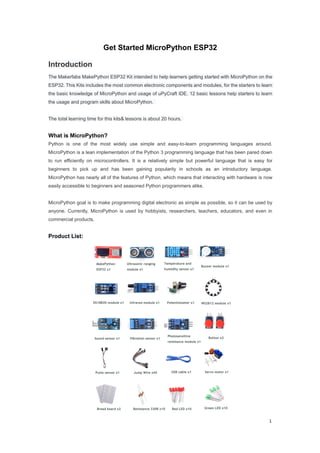
  • 1. 1 Get Started MicroPython ESP32 Introduction The Makerfabs MakePython ESP32 Kit intended to help learners getting started with MicroPython on the ESP32. This Kits includes the most common electronic components and modules, for the starters to learn the basic knowledge of MicroPython and usage of uPyCraft IDE. 12 basic lessons help starters to learn the usage and program skills about MicroPython. The total learning time for this kits& lessons is about 20 hours. What is MicroPython? Python is one of the most widely use simple and easy-to-learn programming languages around. MicroPython is a lean implementation of the Python 3 programming language that has been pared down to run efficiently on microcontrollers. It is a relatively simple but powerful language that is easy for beginners to pick up and has been gaining popularity in schools as an introductory language. MicroPython has nearly all of the features of Python, which means that interacting with hardware is now easily accessible to beginners and seasoned Python programmers alike. MicroPython goal is to make programming digital electronic as simple as possible, so it can be used by anyone. Currently, MicroPython is used by hobbyists, researchers, teachers, educators, and even in commercial products. Product List:
  • 3. 3 Directory Introduction........................................................................................................................................1 What is MicroPython?..................................................................................................................1 Product List....................................................................................................................................1 Makerfabs MakePython ESP32 Pin figure...............................................................................2 I.MicroPython Development Tool.................................................................................................. 3 II.MakePython Lessons...................................................................................................................9 1.Lesson1 LED Control............................................................................................................... 9 2.Lesson2 Running LED...........................................................................................................11 3.Lesson3 Button....................................................................................................................... 13 4.Lesson4 PWM Control...........................................................................................................15 5.Lesson5 Voice Control...........................................................................................................18 6.Lesson6 OLED Display..........................................................................................................21 7.Lesson7 Temperature Monitor DS18B20...........................................................................23 8.Lesson8 Digital LED WS2812.............................................................................................. 25 9.Lesson9 Pulse Sensor...........................................................................................................28 10.Lesson10 AnalogRead........................................................................................................ 30 11.Lesson11 Ultrasonic Ranging............................................................................................ 33 12.Lesson12 WiFi...................................................................................................................... 37 III.Troubleshooting......................................................................................................................... 48 IV.Flash/Upload MicroPython Firmware to ESP32.................................................................. 50 I. MicroPython Development Tool Installing uPyCraft IDE Windows PC There many codes& programming methods with MicroPython. For this tutorial, we use uPyCraft IDE, which is the most simple& easy way for starts to skip into MicroPython. You can learn more about uPyCraft IDE on their GitHub repository or explore the uPyCraft IDE source code. Click this link to download uPyCraft IDE for Windows: https://randomnerdtutorials.com/uPyCraftWindows. After a few seconds you should see a similar file (uPyCraft_VX.exe) in your Downloads folder
  • 4. 4 Double-click that file. A new window opens with the uPyCraft IDE software. A Simple code for blinking an LED on ESP32 as follows: Get Start with uPyCraft IDE Open uPyCraft IDE. Let’s take a closer look at each section of uPyCraft IDE: 1->Folder and files 2->Editor 3->MicroPython Shell/Terminal 4->Tools a. Folder and files This section shows several folders and files. The device folder shows the files that are currently stored on your ESP board. If you have your ESP32 connected via serial to uPyCraft IDE, when you expand the device folder, all files stored should load. By default, you should only have a boot.py file. To run your main
  • 5. 5 code, it is recommended to create a main.py file.  boot.py: runs when the device starts and sets up several configuration options;  main.py: this is the main script that contains your code. It is executed immediately after the boot.py. The sd folder is meant to access files stored on SD cards this is only works with boards like the PyBoard that come with an SD card slot. The uPy_lib shows the built-in IDE library files. The workspace is a directory to save your files. These files are saved in your computer in a directory defined by you. This is a special useful to keep all your files organized at hand. When using uPyCraft for the first time, to select your working directory, click the workspace folder. A new window pops up for you to choose your workspace path. Create a new folder or select an existing folder to be your working directory. Then, go to File > Reflush Directory to update the directory. *Note: to change your user directory, simply go to Tools >InitConfig and click the workspace directory folder to choose a different path. b. Editor The Editor section is where you write your code and edit your .py files. You can open more than one file, and the Editor will open a new tab for each file. c. MicroPython Shell/terminal On the MicroPython Shell you can type commands to be executed immediately by your ESP board without the need of uploading new files. The terminal also provides information about the state of an executing program, shows errors related with upload, syntax errors, prints messages, etc… d. Tools The icons placed at the rightmost side allow you to quickly perform tasks. Each button is labeled in the figure below:  New file: creates a new file on the Editor;  Open file: open a file from your computer;  Save file: saves a file;  Download and run: upload the code to your board and execute the code;
  • 6. 6  Stop: stop the execution of the code – it’s the same as entering CRTL+C on the Shell to stop all scripts from running;  Connect/Disconnect: connect or disconnect to your board via Serial. You must select the serial port first in Tools > Serial;  Undo: undo last change in the code Editor;  Redo: redo last change in the code Editor;  Syntax check: checks the syntax of your code;  Clear: clear the Shell/terminal window messages. Establishing a communication with the board After having the MicroPython firmware installed (MicroPython Firmware already installed when you get Makerfabs MakePython ESP32), connect it to your computer through an USB cable, follow the steps: 1. Tools > Board and select the board you’re using. Select the esp32 2. Go to Tools > Serial and select the com port your ESP is connected to(download the USB driver at: https://www.silabs.com/products/development-tools/software/usb-to-uart-bridge-vcp-drivers) 3. Press the Connect button to establish a serial communication with your board. You will see “>>> “ appear in the Shell window after a successful connection with your board. You can type the print command to test if it’s working. Try to print: >>>print(“hello, world”) It should print the “Hello,World” message. Only if you see that message, you can continue with this tutorial. Otherwise, make sure you have established a serial communication with your board or that you’ve flashed successfully the MicroPython firmware on your board. Creating the main.py file on your board 1. Press the “New file” button to create a new file. 2. Press the “Save file” button to save the file in your computer. 3. A new window opens, name your file main.py and save it in your computer:
  • 7. 7 4. After that, you should see the following in your uPyCraft IDE (the boot.py file in your device and a new tab with the main.py file): 5. Click the “Download and run” button to upload the file to your ESP board 6. The device directory should now load the main.py file. Your ESP has the file main.py stored. Uploading the first Script: Blinking LED Ok, so let’s begin to try to upload a very basic LED blink script into MakePython ESP32 board. 1. Copy the following code to the Editor on the main.py file:
  • 8. 8 From machine import Pin From time import sleep Led = Pin(2, Pin.OUT) while True: Led.value(not led.value()) sleep(0.5) 2. Press the “Stop” button to stop any script from running in your board 3. Click the “Download and Run button” to upload the script to the ESP32. 4. You should see a message saying “download ok” in the Shell window, it means that the updates succeed. To run the script that was just uploaded to your board, you need to press the “Stop” button, then press the on-board ESP32 RST (RESET) button to restart your board and run the script from the start. If you want to run the program on power, you can write code in the main.py file * Note that when there much files in your MakePython boards, it is suggested to delete un-necessary files. Right click the file and select the “delete” to delete these files.
  • 9. 9 II. MakePython Lessons 1. Lesson1: LED Control This is the most basic lesson, in which we will learn how to control the digital output pins with MicroPython, by control the lighting of an LED. Material:  1*LED;  Resistor: 1*330R;  Jump wires; Instructions: The short pin on the left is negative and the long pin on the right is positive. The purpose of resistor is to limit the current, avoid burning LED lamp with too much current. Wiring: Connect the long LED pin to the end of the 330R resistor, the other end of the resistance is connected to 3.3v, the short pin of the LED lamp is connected to the IO5 of ESP32. As follows: Create a file:Open the uPyCraft IDE by clicking , and click save ,to name the Settings file, select your own save path. You can then program in the LED documentation: *Note: The first time you open the uPyCraft IDE, the workSpace path does not exist. When you click, the workSpace dialog box will pop up. You can create a workSpace directory to store the user's files by selecting the directory you want to store.
  • 10. 10 Code and comments: import time #use the time class from machine import Pin #use the machine.Pin class led=Pin(5,Pin.OUT) #create LED object from pin5,Set Pin5 to output try: while True: #repeat the following code led.value(1) #turn off (Set high level) time.sleep(0.5) #waiting for 0.5 seconds led.value(0) #turn on (Set low level) time.sleep(0.5) #waiting for 0.5 seconds except KeyboardInterrupt: pass Grammar explanation:  led=Pin(5,Pin.OUT): Create an LED object and set it to output mode  while: Used to loop through a program, that is, under certain conditions, loop through a segment of a program to handle the same task that needs to be processed repeatedly  led.value(1): Set the led pin value to high level. Since the other pin is connected to 3.3v, there is no voltage difference between the two pins.  led.value(0): Set the pin value to low level, there is a voltage difference between two pins, there is a current through, the LED light is on.  time.sleep(0.5): Delay 0.5 seconds, in this time the control will be sleep and do nothing. The experimental results: Click the to save and the to run, you will see the LED lights blinks with interval of 0.5 seconds. You can try changing it to other pins yourself. For example, change to led=Pin(4,Pin.OUT) , then connect the wire to IO4, and the light will flash, or the delay is changed to time.sleep(1),The light flickers slowly, with interval of1s. You can also try to increase the number of LED lights and keep them on and off. Extension: You can also control the LED lighting by sending command through serial port. *Note: If your lights are still flashing, that means the code is still running, press to stop the program running. Write the code after ">>>" and press enter after each line:
  • 11. 11 code: >>>from machine import Pin #Press enter to jump the cursor to the next line >>>led=Pin(5,Pin.OUT) >>>led.value(1) #Press enter, led off >>>led.value(0) #Press enter, led on * Each time you finish writing the code, you need to press enter and move the cursor to the next line behind “>>>” 2. Lesson2: Running LED In this experiment, multiple LED lights are controlled to deepen the understanding of board GPIO port, compilation environment and program framework. Material:  4*LEDs;  resistance:4*330R;
  • 12. 12  Jump wires; Schematic: Wiring: Connect the short LED pin to the IO15, IO14, IO13 and IO12 of ESP32, and connect the long pin to one end of the 330R resistor and the other end of the resistor to 3.3V: Create a new running_LED file with the following code and comments: from machine import Pin import time #Create an array of Pin15,Pin14,Pin13,Pin12 leds leds = [Pin(15,Pin.OUT),Pin(14,Pin.OUT),Pin(13,Pin.OUT),Pin(12,Pin.OUT)] n=0 try: while True: n = (n+1)%4 #The remainder sign % guarantees that n is between 0 and 3 leds[n].value(1) #The value of the NTH LED is high level,turn off time.sleep_ms(30) #Delay of 30 milliseconds leds[n].value(0) #The value of the NTH LED is low level,turn on time.sleep_ms(30) #Delay of 30 milliseconds except KeyboardInterrupt: pass
  • 13. 13 Grammar:  leds = [Pin(15,Pin.OUT),Pin(14,Pin.OUT),Pin(13,Pin.OUT),Pin(12,Pin.OUT)]: Create an object for each LED lamp and control them separately, declaring a list form that is easy to understand  n = (n+1)%4: n represents the current LED and we can get the value of the next n after each loop execution (the residual symbol % ensures that the value of n is between 0 and 3)  led.value(): 1 for high level, 0 for low level The experimental results: After running the code, you can see four LED lights go on and off in cycles. You can appropriately create more LED objects in the list to make the running lights look better. For example, change to leds=[Pin(15,Pin.OUT),Pin(14,Pin.OUT),Pin(13,Pin.OUT),Pin(12,Pin.OUT),Pin(18,Pin.OUT),Pin(19,Pin. OUT)],n = (n+1)%6 . You can see a row of lights dancing. You can even add more. Try it yourself. 3. Lesson3: Button The LED light in previous lesson is about the usage of output GPIO port. In the lesson, we will learn how to input the signals to the board, by learning the usage of input of GPIO port by pressing buttons. The MakePython ESP32 board will sense the button input, and thus to control the LED ON/OFF. Material:  1*Button Module;  1* LED;  resistance:1*330R;  Jump wires;
  • 14. 14 Instructions: When the button is pressed, VCC is connected to OUT, and OUT pin outputs high level; when the key is released, GND is connected to OUT, and OUT pin outputs low level Wiring: LED wiring is the same as Lesson1. Button VCC pin connects board 3V3, GND connects board GND, OUT pin connects IO12: Create a new Button file with the following code and comments: from machine import Pin import time button=Pin(12,Pin.IN, pull=None) #create Button object from pin12 led=Pin(5,Pin.OUT) #create LED object from pin5,Set Pin5 to output try: while True: if(button.value() == 1): #Press the button, the value is 1, release the button, the value is 0 led.value(0) #turn on else: led.value(1) #turn off except KeyboardInterrupt: pass Grammar explanation:  button=Pin(12,Pin.IN): Create a key object and set it to input mode  if...else: Statement judge, If true, execute the statement after the if. Otherwise, execute the statement after the else Results: Press the button, the LED light is will be on, while release the button, the LED light is off;
  • 15. 15 4. Lesson4: PWM Control Pulse width modulation (PWM) is a method of obtaining artificial analog output on digital pins. It does this by quickly switching pins from low to high. There are two related parameters: switching frequency and duty cycle. Duty cycle is defined as the time a pin is at a high level compared to the length of a single cycle (low level to high level time).The maximum duty cycle is that the guide foot is always at high level while the minimum duty cycle is always at low level We will demonstrate how to use the ESP32 board to generate a PWM signal. For example, by changing duty cycle to reduce the brightness of LED, control steering gear rotation Angle. Material:  1*Servomotor;  1*LED;  1*330R;  Breadboard and jump wires; Instructions: By adjusting the ratio of LED brightness to off in one cycle, the LED brightness can be adjusted. For example, the control cycle of PWM is 100ms, where 33ms is high level and 67ms is low level, and the duty cycle is 33/100=33% Wiring: Connect the long LED pin to the end of the 330R resistor, the other end of the resistance is connected to 3.3v, the short pin of the LED lamp is connected to the IO5 of ESP32. As follows:
  • 16. 16 Create a new PWM file with the following code and comments: from machine import Pin, PWM import time frequency = 5000 #set frequency led = PWM(Pin(5), frequency) #create PWM object from pin5,Set frequency try: while True: for duty_cycle in range(0, 1024): #duty_cycle cycles between 0 and 1024 led.duty(duty_cycle) #duty cycle size of LED lights time.sleep_ms(2) #delay of 2 ms except KeyboardInterrupt: pass Grammar explanation:  led = PWM(Pin(5), frequency): Create the PWM object and set the default frequency  range(): The range() function creates a list of integers and is used in a for loop  for: the for loops can traverse any sequence of items, such as a list or a string  led.duty(): The larger the duty_cycle value of the led, the brighter the led. The experimental results: The LED brightness goes from full bright to dark, then full bright again, and the cycle around, like a breath, which we called “breathing LED” Servo motor is widely used in robot applications. It is an automatic control system composed of dc motor, reduction gear, sensor and control circuit, the rotation angle of the output shaft determined by the input PWM signal.
  • 17. 17 Instructions: Orange wire: Signal , Red wire: Power , Brown wire: GND. Users control the Servo by sending them a fixed frequency square wave signal (usually 50Hz for analog servers, but digital ones may also accept up to 300Hz), we use the duty method to set the Angle, calling the servo.duty () method to change the set servo angle Wiring: The orange line is connected to IO14, the red line is connected to 3.3v, and the brown line is connected to GND: Create a new Servo_Demo file with the following code and comments: import machine import time p14 = machine.Pin(14) servo = machine.PWM(p14,freq=50) try: for i in range(0, 180): servo.duty(i) time.sleep_ms(10) except KeyboardInterrupt: pass Grammar explanation:  servo = machine.PWM(p14,freq=50): Create the PWM object and set the frequency to 50Hz  servo.duty(i): Adjust the duty cycle
  • 18. 18 The experimental results: The servo motor keeps turning. More important: You can also sent the commands to MakePython board to make the servo rotate to any position you want, which is much more convenient in robot application debugging: >>>servo.duty(120) Then the servo will rotate to the position of 120 degree. You can adjust the position by sending commands. 5. Lesson5: Voice Control This experiment will use the buzzer and sound sensor module to do some experiments on sound. Instructions: according to the driving mode is mainly divided into active buzzer and passive buzzer, active buzzer needs dc voltage can drive, passive buzzer needs a specific frequency of vibration signal to drive.The experiment use an active buzzer. Wiring:VCC is connected to 3V3,GND is connected to GND, and I/O is connected to IO12:
  • 19. 19 Create a Buzzer file with code and comments: from machine import Pin,PWM import time pwm=PWM(Pin(12,Pin.OUT)) def ambulenceSiren(pwm): pwm.freq(400) pwm.duty(512) time.sleep_ms(500) pwm.freq(800) time.sleep_ms(500) try: while True: ambulenceSiren(pwm) except KeyboardInterrupt: pwm.deinit() pass Grammar explanation:  Def: Define your own functions, beginning with the def keyword, followed by the function identifier name and parentheses (), within which you can pass arguments and arguments.  pwm.freq(400): Set the frequency at 400Hz, different frequencies produce different sounds The experimental results: You can hear the sound of an ambulance whistle, but you can also modify pwm.freq() to simulate other sounds. With the sound sensor in the kit, we can also make a “sound switch”, that controls an LED On/Off by single sound:
  • 20. 20 Instructions: the sound intensity of the surrounding environment can be detected. When the sound of the external environment fails to reach the set threshold, OUT outputs a high level; when the sound intensity of the environment reaches the set threshold, module OUT outputs a low level. The blue digital potentiometer on the module can be used to adjust the sensitivity. Wiring: VCC is connected to 3V3, GND is grounded, OUT is connected to IO12, and LED is connected to IO5: Create Voice files, code, and comments: from machine import Pin import time voice=Pin(12,Pin.IN) led=Pin(5,Pin.OUT) try: while True: if (voice.value() == 1): led.value(0) time.sleep(1) else : led.value(1) except KeyboardInterrupt: pass
  • 21. 21 The experimental results: When you clap your hands or snap your fingers, you'll notice that the light will be on for 1 second. 6. Lesson6: OLED Display There an on-board OLED 1.3’ OLED module on MakePython board, with 128x64 pixel.One pixel of a monochrome screen is a light-emitting diode. OLED is "self-illumination", the pixel itself is the light source, so the contrast is very high. OLED screens have I2C and SPI communication protocols, which are completely incompatible due to different protocols. In our lesson, the OLED is configured to compatible with I2C protocol Material:  MakePython ESP32: I2C communication: I2C is widely used for controller communicating with onboard components such as sensors/ displays. Data transmission can be completed by only two signal lines, respectively clock line SCL and signal line SDA. There is only one main device Master and several Slave devices on the I2C line. In order to ensure that both buses are at high level when idle, SDA and SCL must be connected with the pull resistor. The classical value of the pull resistor is 10K.
  • 22. 22 Download library function: Since the OLED screen use the SSD1306 driver chip, we need to download the driver of SSD1306. You can go to the github website to search and download the library of SSD1306 or click the following link: https://www.makerfabs.com/makepython-esp32-starter-kit.html Load library function: After downloading, save ssd1306.py to the workSpace file directory. In the workSpace directory, click open the ssd1306.py file and click run, and the library file can be loaded into the device directory. At this time, the library file of ssd1306.py has been successfully loaded into MakePython ESP32, which can be called with the import ssd1306 statement. Create a new ssd1306demo.py file to write the code. As shown in figure: Create a new ssd1306Demo file, code and comments: from machine import Pin,I2C import ssd1306 i2c = I2C(scl=Pin(5), sda=Pin(4), freq=100000) #Init i2c lcd=ssd1306.SSD1306_I2C(128,64,i2c) #create LCD object,Specify col and row
  • 23. 23 try: lcd.text("Makerfabs",30,10) #set "Makerfabs" at (30,10) lcd.text("time:",30,25) #set "time:" at (30,25) lcd.text("2019-12-5",30,40) #set "2019-12-5" at (30,40) lcd.show() #display except KeyboardInterrupt: pass Grammar explanation:  I2C(): Initialize, configure the SCL and SDA pins, and set the frequency at 100000Hz.  lcd.text(): Something to display,The following Numbers are the X and Y axes of the display  lcd.show(): Turn on display function The experimental results: Save and click run, and you'll see Makerfabs/time:/2019-12-5; You can also make it display your own name, etc. Just use the LCD.text() statement to write what you want to display. 7. Lesson7: Temperature Monitor DS18B20 DS18B20 is a low-cost digital temperature sensor. Its measurement range is between -55 ° c and 125 ° c, with an inherent error of 1 ° c and an accuracy of 0.5 ° c between -10 ° c and 85 ° c, which can meet the daily temperature measurement needs. DS18B20 uses OneWire (single-wire) communication protocol, which only needs a signal line to complete the reading and writing of data. Power supply is also allowed to have two modes: independent power supply and data parasitic power supply. In the parasitic power supply mode, the power line is grounded, and the power is obtained from the data line, which can save a connection line. Here we show you how to read data using the OneWire protocol.
  • 24. 24 Instructions: 1:GND; 2:Data(need to connect the pull resistor a 10k resistor to 3.3v);3:VDD Wiring: The GND pins are connected, VCC pin is connected to 3v3, and the DQ pin is connected to IO12. * If there is no ssd1306.py file in the device directory, please download ssd1306.py first. Refer to lesson 6 Create a new DS18B20Demo file, code and comments: from machine import Pin,I2C import ssd1306 import time import machine import onewire, ds18x20 dat = machine.Pin(12) # the device is on GPIO12 i2c = I2C(scl=Pin(5), sda=Pin(4), freq=100000) #Init i2c lcd=ssd1306.SSD1306_I2C(128,64,i2c) #create LCD object,Specify col and row ds = ds18x20.DS18X20(onewire.OneWire(dat)) # create the onewire object roms = ds.scan() # scan for devices on the bus try: while True: ds.convert_temp() time.sleep_ms(750) #The reading temperature needs at least 750ms
  • 25. 25 for rom in roms: lcd.fill(0) lcd.text("temperatures:",10,16) lcd.text(str(ds.read_temp(rom)),24,40) lcd.show() except KeyboardInterrupt: pass Grammar explanation:  scan(): scan for devices on the bus  convert_temp(): Start temperature reading  read_temp(): Read the collected temperature  fill(n): Empty the screen when n=0, and fill the screen when n> is 0 The experimental results: After running, the temperature collected on the display screen appears, which is refreshed every 750ms 8. Lesson8: Digital LED WS2812 WS2812 is an integrated chip low-power RGB trichromatic lamp, chips and full-color legs wrapped together, only 4 pins, each one chip as a full-color "pixel", each pixel end, DIN client receive the data from the controller transfer to come over, every pixel of transmission, signal 24 bit to reduce, all the way. This experiment will teach you how to make colorful LED light rings.
  • 26. 26 Wiring: VDD is connected to 3.3V/5V, VSS is connected to GND, DIN is connected to IO12 of the board: Create a new ws2812Demo file, code and comments: import machine, neopixel import time n = 12 #Define LED quantity np = neopixel.NeoPixel(machine.Pin(12), n) #Create the NeoPixe object def demo(np): # Circular effect.One pixel runs through all strip positions, while the others are closed. for i in range(4 * n): for j in range(n): np[j] = (0, 0, 0) np[i % n] = (255, 255, 255) np.write() time.sleep_ms(25) #Rebound effect and set color (R,G,B), as well as wait time. #Wait time determines the speed of the bounce effect. for i in range(4 * n): for j in range(n):
  • 27. 27 np[j] = (0, 0, 128) if (i // n) % 2 == 0: np[i % n] = (0, 0, 0) else: np[n - 1 - (i % n)] = (0, 0, 0) np.write() time.sleep_ms(60) try: while True: demo(np) except KeyboardInterrupt: pass Grammar explanation:  np = neopixel.NeoPixel(machine.Pin(12), n): Create the NeoPixe object from pin4,set LED quantity  np[i] = (r, g, b): r,g,b: red, green, and blue color channels are each divided into 256 degrees of brightness, with values ranging from 0 to 255, with 0 being the darkest and 255 being the brightest  ”*”: Multiply - multiply the two Numbers  ”%”: Mod - returns the remainder of division  “//”: Take the integral part of the divisible - return quotient  np.write(): Use the write() method to output the colors to the LED The experimental results: Running the code, you can see the brightest white light in the loop, followed by the half-bright blue light bouncing back and forth. You can make colored lights by changing the r,g, and b values of np[i] to get different colors and brightness.
  • 28. 28 9. Lesson9: Pulse Sensor The Pulse Sensor is a photoelectric reflex analog sensor for pulse and heart rate measurement. Wear it on finger, earlobe and so on, make use of the body tissue in the vascular pulse caused by different transmittance to measure pulse. The sensor filters and amplifies the photoelectric signal, and finally outputs the simulated voltage value. Then the heart rate value can be obtained by simple calculation. In this experiment, ADC will be learned through the Pulse Sensor module, and the results will be displayed on the OLED screen. Instructions: On the left is the s-pin of the signal output, in the middle is the positive power supply VCC (3.3v ~5V), and on the right is the negative power supply GND. On the ESP32 ADC functionality is available on Pins 32-39. Note that, when using the default configuration, input voltages on the ADC pin must be between 0.0v and 1.0v (anything above 1.0v will just read as 4095). Attenuation must be applied in order to increase this usable voltage range. Wiring: The s-pin is connected to IO32, the middle pin is connected to 3V3, and the "-" pin is connected to GND:
  • 29. 29 * If there is no ssd1306.py file in the device directory, please download ssd1306.py first. Refer to lesson 6 Create a new pulse file, code and comments: from machine import Pin,ADC import machine from micropython import const import time import ssd1306 import math pscl = machine.Pin(5, machine.Pin.OUT) psda = machine.Pin(4, machine.Pin.OUT) i2c = machine.I2C(scl=pscl, sda=psda) oled = ssd1306.SSD1306_I2C(128, 64, i2c) counttime=0 try: while True: adc = ADC(Pin(32)) #Create ADC object on ADC pin adcValue=adc.read() #read value, 0-4095 across voltage range 0.0v - 1.0v adc.atten(ADC.ATTN_11DB) #set 11dB input attenuation (voltage range roughly 0.0v - 3.6v) adc.width(ADC.WIDTH_10BIT) # set 10 bit return values adcValue=adc.read() # read value using the newly configured attenuation and width oled.line(counttime,40,counttime,adcValue-420,1) #Drew the heart rate oled.show() print(adcValue) time.sleep_ms(1) counttime+=1 if(counttime>127): counttime=0 oled.fill(0) #Clear the screen oled.show() except KeyboardInterrupt: pass Grammar explanation:  counttime: Cache x coordinates (x less than 128)  line(x,y,x1,y1,c): Line function,(x,y): starting point coordinate,(x1,y1): ending point coordinate,c: color The experimental results: Touch the side printed with the heart with your finger, the screen will display your heart rate beat line, the module contact instability or vibration, will affect the measurement data, please save the static measurement.
  • 30. 30 . 10. Lesson10: AnalogRead ADC is an Analog/Digital Converter that converts Analog signals into Digital. In the front control LED on, PWM inside, we know the difference between digital signal and analog signal. The signals we use in everyday life, such as light intensity, sound waves, and battery voltages, are all analog values. If we want to measure the analog signal (voltage, light intensity, sound wave) through the single-chip microcomputer and express it by digital signal, then we need ADC analog digital signal converter Instructions: Potentiometer is an adjustable resistor with three leading ends and resistance values that can be adjusted according to a certain variation law. A potentiometer usually consists of a resistor body and a movable brush. When the brush moves along the resistance body, the resistance value or voltage in relation to the displacement is obtained at the output end. Wiring : The pins on the left and right sides are connected to 3.3V and GND of the plate respectively, the middle pin is connected to IO32:
  • 31. 31 * if there is no ssd1306.py file in the device directory, please download ssd1306.py first. Refer to lesson 6 Create a new ssd1306_adc file, code and comments: from machine import Pin,ADC import machine from micropython import const import time import ssd1306 import math pscl = machine.Pin(5, machine.Pin.OUT) psda = machine.Pin(4, machine.Pin.OUT) i2c = machine.I2C(scl=pscl, sda=psda) oled = ssd1306.SSD1306_I2C(128, 64, i2c) def circle(x,y,r,color,fill=0): if(fill==0): for i in range(x-r,x+r+1): oled.pixel(i,int(y-math.sqrt(r*r-(x-i)*(x-i))),color) oled.pixel(i,int(y+math.sqrt(r*r-(x-i)*(x-i))),color) for i in range(y-r,y+r+1): oled.pixel(int(x-math.sqrt(r*r-(y-i)*(y-i))),i,color) oled.pixel(int(x+math.sqrt(r*r-(y-i)*(y-i))),i,color) else: for i in range(x-r,x+r+1): a=int(math.sqrt(r*r-(x-i)*(x-i)))
  • 32. 32 oled.vline(i,y-a,a*2,color) for i in range(y-r,y+r+1): a=int(math.sqrt(r*r-(y-i)*(y-i))) oled.hline(x-a,i,a*2,color) try: while True: adc = ADC(Pin(32)) #Create ADC object on ADC pin adcValue=adc.read() #read value, 0-4095 across voltage range 0.0v - 1.0v adc.atten(ADC.ATTN_0DB) #0dB attenuation, gives a maximum input voltage of 1v adc.width(ADC.WIDTH_12BIT) # set 12 bit return values, this is the default configuration adcValue=adc.read() # read value using the newly configured attenuation and width time.sleep_ms(10) if(adc.read() == adcValue): oled.fill(0) circle(64,32,adcValue//64,1,1) oled.show() except KeyboardInterrupt: pass Grammar explanation:  adc.read(): Read ADC sampled data  adc.atten(): This method allows for the setting of the amount of attenuation on the input of the ADC. This allows for a wider possible input voltage range, at the cost of accuracy  adc.width(): This method allows for the setting of the number of bits to be utilised and returned during ADC reads  def circle(): Custom draw circle function that USES sqrt () function to calculate the radius of the circle  math.sqrt(r): Returns the square root of the number  pixel(x,y,c): Draw the point at (x,y)  hline(x,y,w,c): Draw a horizontal line, starting at (x,y), length w  vline(x,y,w,c): Draw a vertical line, starting at (x,y), with a height of w The experimental results: By rotating the potentiometer, the circle on the OLED display becomes larger or smaller.
  • 33. 33 11. Lesson11: Ultrasonic Ranging The ultrasonic module is for obstacle& distance measurement. It has stable performance, accurate measurement distance and high precision. The module includes ultrasonic transmitter, receiver and control circuit. Application: robot obstacle avoidance, object ranging, etc Sequence diagram: Ranging principle: to module 1 at least 10 us high level, began after launch eight modules receive the high level of 40 KHZ sound waves, echo the feet will be changed from 0 to 1, MCU start timing, when the ultrasonic module receives the returned acoustic echo from 1 to 0, MCU stop timing, this time is the total
  • 34. 34 time range, in a voice the speed of 340 m/SEC, in addition to 2 is distance. Wiring: VCC is connected to 5V, GND is connected, Trig is connected to IO13, and Echo is connected to IO12: Library function download link: https://www.makerfabs.com/makepython-esp32-starter-kit.html As before, place the hcsr04.py file in the workSpace directory, open it, click run, and load it into the device directory. * if there is no ssd1306.py file in the device directory, please download ssd1306.py first. Refer to lesson 6 Create a new hc_sr04 file, code and comments: from hcsr04 import HCSR04 from machine import Pin,I2C import ssd1306 i2c = I2C(scl=Pin(5), sda=Pin(4), freq=100000) #Init i2c lcd=ssd1306.SSD1306_I2C(128,64,i2c) sensor = HCSR04(trigger_pin=13, echo_pin=12,echo_timeout_us=1000000) try: while True: distance = sensor.distance_cm() print(distance) lcd.fill(0) lcd.text("Distance:",30,20) lcd.text(str(distance),30,40) lcd.show() except KeyboardInterrupt: pass
  • 35. 35 Grammar explanation:  HCSR04(): Set IO port and timeout reminder,  sensor.distance_cm(): Returns the result of the test distance. The experimental results: Point the module at objects in different directions and the OLED displays the distance. Expand: Calling the corresponding library is very convenient, but if you can't find the right library or do not have this library, you need to write the module driver and corresponding procedures, we use ultrasonic module to do experiments, write the driver to achieve its function. First understand the working principle of the module, look at the sequence diagram, for better understanding. You can review how this module works. Step 1: you need to give the Trig pin a high level of 10us, step 2: calculate the time when the Echo pin is in the high level, and step 3: calculate the distance according to the time. Create a new HC-SR04Demo file,Code and comments: from machine import Pin,I2C import ssd1306 import machine import time i2c = I2C(scl=Pin(5), sda=Pin(4), freq=100000) #Init i2c lcd = ssd1306.SSD1306_I2C(128, 64, i2c) trig = Pin(13,Pin.OUT, pull=None) echo = Pin(12, Pin.IN, pull=None) trig.value(0) echo.value(0) def send_pulse_and_wait(echo_timeout_us=500*2*30): trig.value(0) # Stabilize the sensor time.sleep_us(5) trig.value(1)
  • 36. 36 # Send a 10us pulse. time.sleep_us(10) trig.value(0) try: pulse_time = machine.time_pulse_us(echo, 1, echo_timeout_us) return pulse_time except OSError as ex: if ex.args[0] == 110: # 110 = ETIMEDOUT raise OSError('Out of range') raise ex def distance_cm(): pulse_time = send_pulse_and_wait() cms = (pulse_time / 2) / 29.1 return cms def main(): try: while True: distance = distance_cm() print(distance) lcd.fill(0) lcd.text("Distance:",30,20) lcd.text(str(distance),30,40) lcd.show() except KeyboardInterrupt: pass main() Grammar explanation:  time.ticks_us(): Returns an incrementing millisecond counter with any reference point that ends after some value (not specified).This value should be considered opaque and applies only to ticks_diff().  time.ticks_diff(t2,t1): Measure the period between successive calls to ticks_ms() and ticks_us(). Calculate the time from t1 to t2  pass: Empty statement, do nothing, used as a placeholder statement The experimental results: As before, point the module at objects in different directions and the OLED displays the distance.
  • 37. 37 12. Lesson12: WiFi MakePython ESP32 devices have built-in Wifi& Bluetooth, which enables us to access it via Wifi, or connect to your home Wifi network. In this lesson, we will learn how to access MakePython with WebREPL(read-evaluate -print-loop), to control the MakePython pins, and the files uploading/downloading, that users can remote control/upload MakePython, without the need of a USB cable, and also how to make the MakePython be a web-server, with socket communication. 1. WiFi connection Enter help() in MicroPython Shell/terminal, press enter key, and the printed message will prompt you how to set STA mode:  STA Mode: Each terminal connected to a wireless network can be called a site. You can enter the following code one by one in the MicroPython Shell/terminal to connect:  Connect to Internet(STA): >>> import network >>> wlan=network.WLAN(network.STA_IF) #create access-point interface >>> wlan.active(True) #activate the interface >>> wlan.scan() #Scan access point >>> wlan.connect('ap_name','password') #Connect to AP (local WIFI and password) >>>wlan.isconnected() #Check that the workstation is connected to the AP >>> wlan.ifconfig() #Get the IP/netmask/gw/DNS address of the interface Grammar explanation:  wlan.active(True): The activation interface will display:#5 ets_task(4020f4d8, 28, 3fff9e30, 10)  wlan.scan(): Scan the access point and display the network around you
  • 38. 38  wlan.connect('ap_name','password'): Change 'ap_name' and 'password' to your local network name and password to connect  wlan.isconnected(): If the connection is successful, it will return True, if the connection is unsuccessful, it will return False. You need to check whether the network is correct  wlan.ifconfig(): After the connection is successful, the address information of the interface is printed  ap.config(essid='MKF-AP'): Set AP_name, the password defaults to micropythoN,or you can replace this code with:ap.config(essid=' mkf-ap ',authmode=AUTH_WPA_WPA2_PSK,password='12345678') to set the password to12345678,or whatever. Or you can set the connection to WiFi by calling the library provided by us. Here is the download link of the library: https://www.makerfabs.com/makepython-esp32-starter-kit.html Click to download the connectwifi.py file, place it in the workSpace directory, open the file and change the SSID and PASSWORD to local WIF and password. For example, my WIFI name and password are “Makerfabs” and “20160704”, changed to: SSID = "Makerfabs" PASSWORD = "20160704" After saving and clicking run, you can see network config, followed by the IP/netmask/gw/DNS address of the interface:
  • 39. 39 2. WebREPL Before opening WebREPL, we need to enter the following command in the MicroPython Shell/terminal to set it up and press enter: >>>import webrepl >>>import webrepl_setup WebREPL is not turned on by default, follow the prompt to enter: “E” (open), you need to set the password here 4-9 characters(in the example I use “12345”), after two consecutive input, confirm WebREPL open successfully, input: y to restart the board. The following figure shows that the restart was successful: *Note: after setting the password, the device directory will automatically generate a webrepl_cfg.py file to save your password. Maybe you didn't refresh it, so you didn't see it. You can try to disconnect it, then click reconnect, and it will appear. Then you can enter the following 2 commands to start the WebREPL: >>>import webrepl >>>webrepl.start() Then you will see IP address: ws:// 192.168.1.109:8266 Open the webrepl address link: http://micropython.org/webrepl/ Or click the link to download the local version: https://codeload.github.com/micropython/webrepl/zip/master Open WebREPL and modify the address to the previously obtained IP address: ws:// 192.168.1.109:8266, click connect :
  • 40. 40 Enter the password you set before and press enter to connect to WebREPL, on which we can send various commands or programs: By Now, the WebREPL ready to work. You can commit data translation wirelessly, without the USB connection. Example 1: Remember how to turn on an LED light? Now you can type the commands via WebREPL to control the LED On/Off: Example 2: We use the DHT11 module to do an experiment of temperature and humidity measurement and show it through WebREPL Instructions: DHT11 digital temperature and humidity sensor is sensor containing calibrated digital signal output. It applies special digital module acquisition technology and temperature and humidity sensing technology. The sensor consists of a resistive moisture sensor and an NTC temperature sensor. Its precision humidity +-5%RH, temperature +-2℃, range humidity 20-90%RH, temperature 0~50℃.VCC power positive pole : 3V~ 5.5v,GND: power negative ground, DATA: serial DATA pin; Wiring: VCC is connected to 3.3v, and DATA is connected to IO14:
  • 41. 41 Create a new DHT11 file, code and comments: from machine import Pin import dht import time p14=Pin(14, Pin.IN) d=dht.DHT11(p14) try: while True: d.measure() #Measurement of temperature and humidity t=d.temperature() #Read Celsius temperature h=d.humidity() #Read relative humidity print('Temperature=', t, 'C', 'Humidity=', h, '%') time.sleep(1) #Delay of 1 second except KeyboardInterrupt: pass Grammar explanation:  measure(): Measurement of temperature and humidity  temperature(): Read Celsius temperature  humidity(): Read relative humidity We can upload files through WebREPL and show the effects of temperature and humidity in WebREPL. In the WebREPL, Click select file to find the dht11.py file stored in the workSpace directory, and click Send to device:
  • 42. 42 After sending, enter the command import os and os.listdir() to view the file directory, which adds a dht11.py file to indicate that the upload was successful: >>>import os >>>os.listdir() Commit the built-in statement of exec and execute the file dht11.py. Code: >>>exec(open(‘DHT11.py’).read(),globals()) 3. Socket communication Socket communication is the basis of Internet communication. It is the basic operation unit of network communication that supports TCP/IP protocol. To establish Socket communication requires a server side and a client side. This routine will use Python ESP32 as the client and computer browser as the server side. Both sides will use TCP protocol to transmit and receive data from each other. Example_1: Socket Communication LED Remote control In this example, we will make the MakePython as a server with LED, so the customer can assess the LED control remotely with any computer, as he/she get the right IP address. The Socket_LED source code: #webserver.py import network import webrepl import time from machine import Pin try: import usocket as socket except: import socket AUTH_OPEN = 0 AUTH_WEP = 1 AUTH_WPA_PSK = 2
  • 43. 43 AUTH_WPA2_PSK = 3 AUTH_WPA_WPA2_PSK = 4 SSID = "xxx" #Modify here with SSID PASSWORD = "xxx" #Modify here with PWD led = Pin(5, Pin.OUT) def web_page(): html = """<html><head><meta name="viewport" content="width=device-width, initial-scale=1"></head> <body><h1>Makerfabs Web Server</h1><a href="?led=on"><button>ON</button></a>&nbsp; <a href="?led=off"><button>OFF</button></a></body></html>""" return html def do_connect(ssid,psw): import network import time wlan = network.WLAN(network.STA_IF) wlan.active(True) s = wlan.config("mac") mac = ('%02x:%02x:%02x:%02x:%02x:%02x').upper() %(s[0],s[1],s[2],s[3],s[4],s[5]) print("Local MAC:"+mac) #get mac wlan.connect(ssid, psw) if not wlan.isconnected(): print('connecting to network...' + ssid) wlan.connect(ssid, psw) start = time.ticks_ms() # get millisecond counter while not wlan.isconnected(): time.sleep(1) # sleep for 1 second if time.ticks_ms()-start > 20000: print("connect timeout!") break if wlan.isconnected(): print('network config:', wlan.ifconfig()) return wlan def connect(): do_connect(SSID,PASSWORD) def app(): connect() s = socket.socket(socket.AF_INET, socket.SOCK_STREAM)
  • 44. 44 s.bind(('', 80)) s.listen(5) while True: conn, addr = s.accept() print('Got a connection from %s' % str(addr)) request = conn.recv(1024) request = str(request) print('Content = %s' % request) led_on = request.find('/?led=on') led_off = request.find('/?led=off') if led_on == 6: print('LED ON') led.value(0) if led_off == 6: print('LED OFF') led.value(1) response = web_page() conn.send('HTTP/1.1 200 OKn') conn.send('Content-Type: text/htmln') conn.send('Connection: closenn') conn.sendall(response) conn.close() app() Code download link: https://www.makerfabs.com/makepython-esp32-starter-kit.html Grammar explanation:  web_page(): Create a simple web interface  s = socket.socket(socket.AF_INET, socket.SOCK_STREAM): Create the socket object,AF_INET->IPV4,SOCK_STREAM->TCP  s.bind(address): Bindings for service roles  s.listen(i): Listen, for service roles, I: number of allowed connections, must be greater than 0  s.accept(): Accept the connection for the service role  conn.recv(): Receive data  conn.send(): Send data  conn.close(): Close data connection
  • 45. 45 The experimental results: Change SSID and Password to local network name and Password. The LED wiring is the same as Lesson1. When connecting to the router, you can see the IP address printed out of the serial port: Enter the IP address printed from the serial port in any browser, with any computer in the same WIFI, to control the LED on/off: Example_2: Socket Communication Remote Monitoring In addition to sending command and control LED lights, it can also receive measurement data. The DHT11 module is still used in this experiment. With the Socket communication, the MakePython can be also a server to detect environment and report to the Internet for sharing. In this example, the MakePython be a temperature& humidity server, so any PC could assess it to get the related info. Socket_DHT11 Sample code: #main.py import network import webrepl import dht import time from machine import Pin try: import usocket as socket except: import socket AUTH_OPEN = 0 AUTH_WEP = 1 AUTH_WPA_PSK = 2 AUTH_WPA2_PSK = 3 AUTH_WPA_WPA2_PSK = 4
  • 46. 46 SSID = "Makerfabs" PASSWORD = "20160704" sensor = dht.DHT11(Pin(14)) def read_sensor(): global temp, temp_percentage, hum temp = temp_percentage = hum = 0 try: sensor.measure() temp = sensor.temperature() hum = sensor.humidity() print(temp) print(hum) if (isinstance(temp, float) and isinstance(hum, float)) or (isinstance(temp, int) and isinstance(hum, int)): msg = (b'{0:3.1f},{1:3.1f}'.format(temp, hum)) temp_percentage = (temp+6)/(40+6)*(100) hum = round(hum, 2) return(msg) else: return('Invalid sensor readings.') except OSError as e: return('Failed to read sensor.') def web_page(): html = """<html><head><meta name="viewport" content="width=device-width, initial-scale=1"> <style>body{padding: 20px; margin: auto; width: 50%; text-align: center;} .progress{background-color: #F5F5F5;} .progress.vertical{position: relative; width: 25%; height: 60%; display: inline-block; margin: 20px;} .progress.vertical > .progress-bar{width: 100% !important;position: absolute;bottom: 0;} .progress-bar{background: linear-gradient(to top, #f5af19 0%, #f12711 100%);} .progress-bar-hum{background: linear-gradient(to top, #9CECFB 0%, #65C7F7 50%, #0052D4 100%);} p{position: absolute; font-size: 1.5rem; top: 50%; left: 50%; transform: translate(-50%, -50%); z-index: 5;}</style></head> <body><h1>Makerfabs DHT Sensor</h1><div class="progress vertical"> <p>"""+str(temp)+"""C<p> <div role="progressbar" style="height: """+str(temp_percentage)+"""%;" class="progress-bar"></div></div><div class="progress vertical"> <p>"""+str(hum)+"""%</p> <div role="progressbar" style="height: """+str(hum)+"""%;" class="progress-bar progress-bar-hum"></div></div></body></html>""" return html
  • 47. 47 def do_connect(ssid, psw): import network import time wlan = network.WLAN(network.STA_IF) wlan.active(True) s = wlan.config("mac") mac = ('%02x:%02x:%02x:%02x:%02x:%02x').upper() %(s[0],s[1],s[2],s[3],s[4],s[5]) print(" Local MAC:"+mac) #get mac wlan.connect(ssid, psw) if not wlan.isconnected(): print('connecting to network...' + ssid) wlan.connect(ssid, psw) start = time.ticks_ms() # get millisecond counter while not wlan.isconnected(): time.sleep(1) # sleep for 1 second if time.ticks_ms()-start > 20000: print("connect timeout!") break if wlan.isconnected(): print('network config:', wlan.ifconfig()) return wlan def connect(): do_connect(SSID,PASSWORD) def app(): connect() s = socket.socket(socket.AF_INET, socket.SOCK_STREAM) s.bind(('', 80)) s.listen(5) while True: conn, addr = s.accept() print('Got a connection from %s' % str(addr)) request = conn.recv(1024) print('Content = %s' % str(request)) sensor_readings = read_sensor() print(sensor_readings) response = web_page() conn.send('HTTP/1.1 200 OKn') conn.send('Content-Type: text/htmln') conn.send('Connection: closenn') conn.sendall(response)
  • 48. 48 conn.close() app() Code download link: https://www.makerfabs.com/makepython-esp32-starter-kit.html Please refer to the previous examples for code comments and DHT11 wiring. It will not be repeated here. The experimental results: Modify SSID and PASSWORD in the code and restart. If the program runs and connects to the router, the serial port can be seen to print out the IP address: Open your IP with any computer in the WIFI could access this temperature& humidity monitor now, by entering the IP address in any browser: *note: some browsers are not supported, this example was tested using the Chrome browser III. Troubleshooting We’ve discovered some common problems and error messages that occur with uPyCraft IDE. Usually restarting your ESP with the on-board RST button fixes your problem. Or pressing the uPyCraft IDE “Stop” button and repeating your desired action. In case it doesn’t work for you, read these next common errors and discover how to solve them Error #1: You get the following message:
  • 49. 49 Or an equivalent message: Unplug, and plug back your ESP board. Then, double-check that you’ve selected the right serial port in the Tools > Serial menu. Then, click the “Connect/disconnect” button to establish a serial communication. You should now be able to upload a new script or re-run new code. This error might also mean that you have your serial port being used in another program (like a serial terminal or in the Arduino IDE). Double-check that you’ve closed all the programs that might be establishing a serial communication with your ESP board. Then, unplug and plug back your ESP board. Finally, restart the uPyCraft IDE – try to select the serial port in the Tools > Serial menu. Error #2: Trouble uploading a new script. Press the “Stop” button in uPyCraft IDE (1 or 2 times) to make sure any code that was running stops. After that, press the “Download and run” button to upload the new script to your ESP board. Error #3: After uploading a new script, if you see the following message: Or this message: It means the new file was uploaded to your board successfully. You can notice that it printed the “download ok” message. Press the ESP on-board “EN/RST” button to restart your board and re-run the new uploaded script from the beginning. Error #4: Problem restarting your ESP board, running a new script or opening the serial port:
  • 50. 50 The “Brownout detector was triggered” error message means that there’s some sort of hardware problem. It’s often related to one of the following issues:  Poor quality USB cable;  USB cable is too long;  Board with some defect (bad solder joints);  Bad computer USB port;  Or not enough power provided by the computer USB port Solution: try a different shorter USB cable (with data wires), try a different computer USB port or use a USB hub with an external power supply. Important: if you keep having constant problems or weird error messages, we recommend re-flashing your ESP board with the latest version of MicroPython firmware: Flash/Upload MicroPython Firmware to ESP32.(The next chapter will have specific tutorials) Error #5: When I try to open a serial communication with the ESP32 in uPyCraft IDE, sometimes it prompts the “Burn Firmware” window asking to re-flash the MicroPython firmware. Basically, we think this is what’s happening: when you’re running a script in your board, sometimes it’s busy running that script and performing the tasks. So, you need to try opening the COM port multiple times or restart the ESP to catch it available to establish the serial communication with uPyCraft IDE. If you’re running a script that uses Wi-Fi, deep sleep, or it’s doing multiple tasks, I recommend trying 3 or 4 times to establish the communication. If you can’t, I recommend re-flash the ESP with MicroPython firmware. IV. Flash/Upload MicroPython Firmware to ESP32 This chapter shows how to flash MicroPython firmware to ESP32 boards using the uPyCraft IDE software. It works on Windows, Linux, and Mac OS X. Note the MakePython is programmed Micropython by default, that you do not need to do this before the experiments. This is just for Micropython updating. To download the latest version of MicroPython firmware for the ESP32, go to the http://micropython.org/download#ESP32 and scroll all the way down to the ESP32 section. You should see a similar web page (see figure below) with the latest link to download the ESP32 .bin file – for example:esp32-20181007-v1.9.4-631-g338635ccc.bin.
  • 51. 51 Selecting Serial Port Go to Tools > Serial and select your ESP32 COM port (in our case it’s COM5). Important: if you plug your ESP32 board to your computer, but you can’t find the ESP32 Port available in your uPyCraft IDE, it might be one of these two problems: 1. USB drivers missing or 2. USB cable without data wires. You can download the CP2102 drivers through the following link: https://www.silabs.com/products/development-tools/software/usb-to-uart-bridg e-vcp-drivers After they are installed, restart the uPyCraft IDE and you should see the COM port in the Tools menu. If you have the drivers installed, but you can’t see your device, double-check that you’re using a USB cable with data wires. USB cables from powerbanks often don’t have data wires (they are charge only). So, your computer will never establish a serial communication with your ESP32. Using a a proper USB cable should solve your problem. Selecting the Board Go to Tools > Board. For this tutorial, we assume that you’re using the ESP32, so make sure you select the “ESP32” option:
  • 52. 52 Flashing/Uploading MicroPython Firmware Finally, go to Tools > BurnFirmware menu to flash your ESP32 with MicroPython. Select all these options to flash the ESP32 board:  board: ESP32  burn_addr: 0x1000  erase_flash: yes  com: COMX (in our case it’s COM5)  Firmware: Select“Users”and choose the ESP32 .bin file downloaded earlier
  • 53. 53 After pressing the “Choose” button, navigate to your Downloads folder and select the ESP32 .bin file:
  • 54. 54 Having all the settings selected, hold-down the “FLASH” button in your ESP32 board: While holding down the “FLASH“, click the “ok” button in the burn firmware window: When the “EraseFlash” process begins, you can release the “FLASH” button. After a few seconds, the firmware will be flashed into your ESP32 board. *Note: if the “EraseFlash” bar doesn’t move and you see an error message saying “erase false.“, it means that your ESP32 wasn’t in flashing mode. You need to repeat all the steps described earlier and hold the “FLASH” button again to ensure that your ESP32 goes into flashing mode.
  • 55. 55 fab service for brilliant ideas Description: This MakePython ESP32 Kits includes the basic components and guidance for MicroPython starters. With the 12 experiments in this guide, you will be able to make simple electronic projects with MicroPython on ESP32, and the basic knowledge& usage of IOT projects. About Makerfabs Makerfabs is open hardware facilitator based on Shenzhen, China, We make open hardware projects and help our customers project prototyping& small batch production, includes PCBA/ Molding/ OEM. Contact service@makerfabs.com for more info.