Pb2003.01 problems with the electrostatic discharge (esd) immunity test in electromagnetic compatibility (emc)

Electrostatic discharge (ESD) immunity test is one of the important electromagnetic compatibility (EMC) tests. The IEC standard IECdlOOO-4-2 is the widely used standard to test the ESD immunity for electronic equipment. Many amendments such as amendment 1 (1998), amendment 2 (2000) have been published since 1995, but there is still problems with the ESD immunity test even with the 200x version. More than six ESD generators of different bands are tested for different equipment. The results show that the failure voltages of different ESD generators are vary much from different bands for the same test equipment. This may lead to the results incomparable when test the ESD immunity test in the EMC. Further studies show that there is a good correlation between the failure voltage and the induced voltage.

Recommended
Recommended
More Related Content
What's hot
What's hot (20)
Similar to Pb2003.01 problems with the electrostatic discharge (esd) immunity test in electromagnetic compatibility (emc)
Similar to Pb2003.01 problems with the electrostatic discharge (esd) immunity test in electromagnetic compatibility (emc) (20)
More from ESDEMC Technology LLC
More from ESDEMC Technology LLC (6)
Recently uploaded
Recently uploaded (20)
Pb2003.01 problems with the electrostatic discharge (esd) immunity test in electromagnetic compatibility (emc)
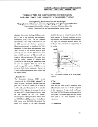
- 1. Asia-Pacific Conferenceon Environmental Electromagnetics CEEM' 2003 Nov. 47,2003 HanPzhou.China PROBLEMS WITH THE ELECTROSTATICDISCHARGE (ESD) IMMUNITY TEST IN ELECTROMAGNETIC COMPATIBILITY(EMC) Jiusheng Huang*, David Pommerenke**, Wei Huang** *)Beijing Institute of Electromechanical Technology,Beijing, China,jshuang@ESD-China.Com **) Electromagnetic Compatibility Laboratory,University of Missouri-Rolla, USA ***) Beijing University of Post and Telecommunication, Beijing, China Abstract- Electrostatic discharge (ESD) immunity test is one of the important electromagnetic compatibility (EMC) tests. The IEC standard IECdlOOO-4-2 is the widely used standard to test the ESD immunity for electronic equipments. Many amendments such as amendment 1 (1998), amendment 2 (2000) have been published since 1995, but there is still problems with the ESD immunity test even with the 200x version. More than six ESD generators of different bands are tested for different equipments. The results show that the failure voltages of diferent ESD generators are vary muchfrom different bandsfor the same test equipment. This may lead to the results incomparable when test the ESD immunity test in the EMC. Further studies show that there is a good correlation between thefailure voltage and the induced voltage. 1. Introduction The electrostatic discharge (ESD) current waveform of the IEC61000-4-2 s&ndard[11 is shown in figure 1. It says the rise time of the first peak is 0.7-1 ns and the current is in the range of 3.375-4.125 A/kv. The current at 30 ns is in the range of 1.4-2.6 A/kv and the current at 60 ns is in the range of 0.7-1.3~kv.Many works were made on the research of the ESD current, electromagnetic and magnetic field radiated from the ESD[2-51. Any ESD generator is standard if its ESD current is per IEC61000-4-2 standard. The failure ESD voltage for the same equipment should be the same in certain tolerances. But the failure voltages for the same equipment are very large for more than six bands of ESD generators. This paper is to investigate the main reasons and the factors which influence the compatibility of the results. 3.75 +I- lox I I I 60"s ^crc lr = 0 7 b 1 ns Fig. 1 ESD current waveform of the IEC61000-4-2 standard 2. Test 2.1 Test setups More than six bands of ESD simulators from different factors were used as the test equipment of the experiment. A high speed oscilloscope (TekTonix TDS7404 Phosphor oscilloscope 4GHz, 20GS/s) and ESD current targets and field sensors were used as the main equipment in our experiment. 2.2. Test Results 7-5I
- 2. All the ESD generators are calibrated as the IEC61000-4-2 standard requirements. They have the same ESD current as the standard. The ESD failure voltages of the same electronic equipment for different bands of ESD generators were tested. The failure voltage may be very much from 1kV to even 6kV for the same equipment even if all the ESD current are accordant with the same standard. This may lead to the results incomparable when test the ESD immunity test in the EMC. ._._.- - . . . - . ..... - . --- .- ... .- 0 7 6 5 4 3 2 1 n Fig. 2 ESD susceptibility of computer by different ESD generators with the same ESD currents 2.2.1 The influence of the ground strip to the ESD current waveform Many factors such as the parasitic capacitors and inductors will influence the waveform of the ESD current and the failure voltage in our experiments. The rise time, the first peak of the ESD current and the shape of waveforms of the ESD current are easily influenced by those factors. But those parasitic capacitors and inductors are constant in a given ESD generator when it is made in the factor. Other factors such as the length and shape of the ground strip are vary in the practice experiment. The waveform of the second segment is influenced by the RC network and the shape and position of the ground strip. Several tests are made to demonstrate the effects. A ESD generator is used to test the waveform. The results are shown in figure 3 and figure 4. Figure 4 has some offset in order to observe easily (Total Y offset 70%, Total X offset 20%) Fig. 3 The ESD current waveform influenced by the differentshape and position of the ground strip Fig. 4 The ESD current waveform (shown in different offset of XY position) influenced by the differentshape and position of the ground strip It can be seen from figure 3 and figure 4 that when the ground strip is in winding, that is the inductance is very large, the waveform (Black) vibrating during the decay period. When the ground strip is in straight line, the waveform (Blue) is very similar to the waveform proposed by IEC standard. When tlhe ground strip is in other shape and position, the waveform is also influenced by the inductance. 2.2.2 ESD induced voltage Voltage induced by both the electric field and magnetic field radiated from ESD at a given distance can be easily measured than that of the 252
- 3. electric field and magnetic field. It is mainly the induced voltage which makes the electronic equipment failure. So, more attention will be paid to the induced voltage. There &e two typical induced voltages which represent the real effects of ESD. One is the monopole induced voltage. It is mainly induced by electric field. Another is the loop induced voltage which may be induced by both magnetic field and electric field if the sensor is not electric shielded. In order to test the ESD current, monopole induced voltage and loop induced voltage. Three channels of the digital oscilloscope is connected to ESD current target, monopole with 10" length and the half circular loop with diameter of 13 mm respectively. It will be unstable due to the lower sampling rate when three or more channels are used simultaneously. But the concurrent phenomena can be easily observed. 7 ' - 4 6- 5 - > . .._-3 4 - s 2 3 - n . V I , 0 In 2 -w 1 - dllll dxl.3( dJ-I.E i n1 m v n hll TYIxSraCnlr 1a** Ch3 Zahv a D* m m II b b o r m h v Fig.5 ESD current, monopole induced voltage and loop inducedvoltage r 2.3 ESD current and ESD induced voltage In order to test the ESD current and ESD induced voltage in the sensor. Two channels of the oscilloscope are connected the ESD current target and the loop sensor. The ESD current is much varies with the ESD induced voltage in shape and duration. The induced voltage is very short in duration than that of the ESD current shown in Fig.6. The induced voltage may be small just like noise after several ns even if the ESD current is increase. I i _ - --Q1lnlwJ C Ch2 5nCral C Fig. 6 shorttime of lOns Figure 6 shows that the ESD current will increase after 10 nanoseconds due to the discharge of the capacitor in the ESD. But the induced voltage doesn't increase any more. This further demonstrates that the induced voltage doesn't correlate with the ESD current. ESD currentand ESD induced voltage in the I 7 1 .I y=6.91881-9.71634~1 ',~.. Correlation coefficientR= 4.88567 ."-... Standard deviationSD= 0.86476 ." '...I'. .'....... .'... '... ".m a... 0.2 0.3 0.4 0.5 0.6 ESD Induced Loop Voltage Vp-p(V) 7 0.7 I ' Fig. 7 For the same equipment the failure level of discharge may be from 1kV to 6kV. But there is good correlation between the ESD susceptibility and induced voltage from different simulators. The correlation coefficient R= -0.88567, standard deviation SD= 0.86476[2]. ESD susceptibilityand induced voltage 253
- 4. 3. Conclusions and Future Works ESD current for different ESD simulators are tested. The ESD susceptibility of computer with different CPU and auto switch are experimentally investigaied. ESD induced voltage are tested for different ESD simulators. Some conclusions are summarized [51. 1. The parasitic inductor and capacitor of the ESD simulator are critical factors which will influenced the both the waveform of the ESD current and the ESD model of discharge, Different ESD simulators have different parasitic parameters that lead to the different ESD susceptibility. 2. The shape and position of the ground strip of the ESD simulator will influence the inductor of the LCR and lead to the generation of different waveform of the ESD current. These two factors are mainly source lead to the variation of the ESD susceptibility of the electronic equipment. 3. ESD induced voltage doesn’t correlate with the ESD current but it is correlated with the induced voltage. It is generated by the process of contact of the relay in the ESD. The duration of the ESD voltage is about 5 nanoseconds and the typical duration of ESD current is more than 100 nanoseconds. The ESD susceptibility is very complicated. It may be influenced by both the ESD current and Electromagnetic,and magnetic field radiated from the ESD. If the ESD current and the induced voltage can be defined more exactly, the ESD susceptibility test results may be more repeatable I Acknowledgements Thanks go out to Dr. Thomas Van Doren of EMC laboratory, University of Missouri-Rolla for his warmly supports to the ESD work, Kai Wang and all students in UMR for their supports and helps during my stay in UMR from 2002-2003. [I] IEC 61000-4-2 Electromagnetic Compatibility (EMC)- Part 4-:!: Testing and measurement techniques -Electrostatic discharge immunity test (1995,1998,2000) [2]Jiusheng Huang, David Pommerenke etc. Investigation of ESD Current and Induced Voltage from Different ESD Simulators, Proceeding of ESA-IEEE Joint ’4nnual Meetings, Little Rock, Arkansas,USA, June. 24-28,2003 [3] The Study of Transient Fields Generated by Typical ESD Models, Proceedings of the Fourth Intemational Conference on Applied Electrostatics, The 4th Intemational Conference on Applied Electrostatics, pp.585-588, Dalian, China, [4]Pommerenke, D., Aidam, M., ‘ESD: Waveform calculation, field and current of human and simulator ESD’, Journal of Electrostatics, Vol. 38, Issues 1-2, Oct.8-12,2001 Oct. 1996,pp. 33 - 51 [5] Jiusheng Huang, ESD Test report, EMC Laboratory, Univers.ityof Missouri-Rolla,USA ‘References