Analysis and optimization of electrodes for improving the performance of ring laser gyro

Abstract Performance of Ring Laser Gyros (RLGs) solely depends upon the stability of scale factor. Variation in scale factor is directly related to the changes in the path length of the gyros. Any thermal and mechanical gradients are mainly responsible for variation in path length. In the case of prism based RLGs, electrodes are utilized for RF discharge to excite the gain medium (He-Ne Laser) as well as for sustenance of laser. Due to the near proximity of the prism with respect to discharge, it gets heated up. Due to heating of prisms, the refractive index of the material of the prism also changes. This change in refractive index in turn affects the stability of the scale factor. In the present work experiment has been carried out to study and optimize the electrode length for achieving the desired output power and vice a versa to improve the performance of Ring Laser Gyros. Keywords: RLG, Scale factor, Path length, RF discharge, Self heating and Refractive Index

Recommended
Recommended
More Related Content
What's hot
What's hot (20)
Viewers also liked
Viewers also liked (19)
Similar to Analysis and optimization of electrodes for improving the performance of ring laser gyro
Similar to Analysis and optimization of electrodes for improving the performance of ring laser gyro (20)
More from eSAT Journals
More from eSAT Journals (20)
Recently uploaded
Recently uploaded (20)
Analysis and optimization of electrodes for improving the performance of ring laser gyro
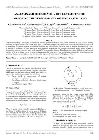
- 1. IJRET: International Journal of Research in Engineering and Technology eISSN: 2319-1163 | pISSN: 2321-7308 _______________________________________________________________________________________ Volume: 04 Issue: 05 | May-2015, Available @ http://www.ijret.org 112 ANALYSIS AND OPTIMIZATION OF ELECTRODES FOR IMPROVING THE PERFORMANCE OF RING LASER GYRO A. Ramchander Rao1 , G.Laxminarayana2 , M.K.Gupta3 , I.M.Chhabra4 , C. Vishnuvardhan Reddy5 1 Research Scholar, Department of Physics, Osmania University, Telangana, India 2 Scientist, Laser Systems, Research Center Imarat, Telangana, India 3 Scientist, Laser Systems, Research Center Imarat, Telangana, India 4 Scientist, Laser Systems, Research Center Imarat, Telangana, India 5 Professor, Department of Physics, Osmania University, Telangana, India Abstract Performance of Ring Laser Gyros (RLGs) solely depends upon the stability of scale factor. Variation in scale factor is directly related to the changes in the path length of the gyros. Any thermal and mechanical gradients are mainly responsible for variation in path length. In the case of prism based RLGs, electrodes are utilized for RF discharge to excite the gain medium (He-Ne Laser) as well as for sustenance of laser. Due to the near proximity of the prism with respect to discharge, it gets heated up. Due to heating of prisms, the refractive index of the material of the prism also changes. This change in refractive index in turn affects the stability of the scale factor. In the present work experiment has been carried out to study and optimize the electrode length for achieving the desired output power and vice a versa to improve the performance of Ring Laser Gyros. Keywords: RLG, Scale factor, Path length, RF discharge, Self heating and Refractive Index --------------------------------------------------------------------***---------------------------------------------------------------------- 1. INTRODUCTION Gyro is an instrument which senses inertial angular motion about its input axis without external reference. Three most widely used physical principles on which successful gyro technologies are based can be described as follows: Gyros based on Conservation of angular momentum of a spinning rotor Gyros based on Coriolis effect on a vibrating mass or structure Gyros based on Sagnac Effect 1.1 Sagnac Effect If two counter propagating light beams travel in a closed circular path after entering at a point P in inertial space, then the travel time for both the beams are same in the absence of an inertial rotation perpendicular to the plane of the circular path as the beams traverse the same optical path and exit at the same point P in inertial space. The travel time is given as t0 = 2 𝜋𝑅 𝑐 . ----(1) When the closed path is rotated at angular rate Ω , then the travel time for both the beams is not the same as the beams have entered at P but leave from another point P1 that is fixed in inertial space. This means that the rotation has created a path length difference ∆L between the counter Fig: 1.1 Sagnac Effect gyro principle P – Light beam entry, P1 – Light beam exit , ∆L – path length difference propagating beams in the closed optical path. This phenomenon is called Sagnac effect. The path length difference ∆L is given by c ∆t. The difference in the beam travel time ∆t, due to path length difference ∆L to a first order of approximation is given by ∆t = 4𝜋𝑅2 𝑐2 Ω = 4 𝐴 𝑐2 Ω -----(2) Where,A – area enclosed by the closed optical path A = π R2 c – velocity of light in the medium Ω - input angular rate about inertial space 2. THEORETICAL DETAILS The Ring Laser Gyro (RLG) is the outcome of extensive research for a solid state gyro as an alternative to spinning rotor gyro technology. In this process of evolution, some of
- 2. IJRET: International Journal of Research in Engineering and Technology eISSN: 2319-1163 | pISSN: 2321-7308 _______________________________________________________________________________________ Volume: 04 Issue: 05 | May-2015, Available @ http://www.ijret.org 113 the earlier designs and configurations of RLG became obsolete, such as 5 sided gyro or the gyro with magnetic mirrors. The active resonator concept followed in RLG motivated research and technology. 2.1 Ring Laser Resonator The important part of the ring laser gyro operation is to create a ring type laser resonator which can detect the rotation induced Sagnac phase difference. There are two design conditions to be fulfilled to achieve a ring resonator. First, In a resonator, the gain provided by the amplifying medium must exceed the losses in the cavity due to various reasons. Second, The resonator oscillation is determined by the condition that the optical path length (L) for the beam to return to itself, is an integral number (m) of wavelength (λ), so that the relation L = m λ is ensured. Under such resonating conditions in a ring laser resonator, the clockwise (cw) and the counter - clockwise (ccw) beams are created that travel with identical frequency in the resonator cavity. When the ring laser cavity is rotated, Sagnac effect causes a change in the optical path length of one beam relative to the other, which in turn results in the two beams to have different oscillation frequency. Transforming the optical path length difference to a more measurable frequency difference provides an elegant instrumentation scheme that forms the basis of RLG rate detection. The fundamental relationship to define the operation of a basic ring laser gyro is termed as 𝑓𝑐𝑐𝑤 − 𝑓𝑐𝑤 = ∆𝑓 = 4 𝐴 𝜆𝐿 Ω ----(3) Where, ∆f - frequency difference between ccw and cw beams A – closed optical path area λ - laser beam wavelength L - closed optical path length Ω - input angular rate about inertial space. In reality the RLG rate detection scheme is mechanized to measure the rotation angle by integrating the above expression. Hence, 𝑁𝑓𝑟𝑖𝑛𝑔𝑒𝑠 = 4 𝐴 𝜆𝐿 ∆Ө ----(4) Where N fringes represents the number of fringes that is traversed when the gyro is rotated through an angle ∆Ө. The Scale factor of RLG can be deduced by putting N = 1 and the gyro scale factor S k is given as 𝑆𝑘 = 𝜆 𝐿 4 𝐴 ----(5) The unit of scale factor is radian / pulse or arc – sec / pulse. The word count is used instead of pulse. In RLG when the two frequencies are equal, the fringes are stationary in time. When the frequencies are different, the fringes move across the field of view. By measuring the number of fringes moving across the field of view for a fixed time, the angular rate can be determined by using the scale factor Sk . A simple counting of the fringes provides the inertial rotation angle. 2.2 Design of RLG with TRP on Four Sides The design and development of RLG were focused on the requirement for an autonomous navigation grade strap down gyro with high reliability and producibility. As expected, the technology evolved through a number of configurations involving various designs concerning all the key areas. All these research and development activities eventually converged on a few variants of design which are described further under the functional and design elements namely, Ring resonator which primarily consists of gas medium, gas discharge and mirrors or reflectors or prisms Path Length Control Readout of Rotation Block Material Number of sides Lock – in Solutions Considering the critical technology that is associated with each of these functional elements in association with the relevant tooling and manufacturing set – ups, each RLG become a unique product where any change of a functional element becomes extremely difficult. Fig: 1.2 Ring Resonator Geometry 3. EXPERIMENTAL SET UP The most widely used lasing medium inside the cavity is a gas that is a mixture of Helium (He) and Neon (Ne). The gas fill pressure and the He-Ne mixture ratio are the important controlling parameters for resonator operation and these are design specific. Control on these parameters establishes the various aspects of the resonator, such as laser gain, gyro thermal sensitivity and performance. The use of four Total Reflecting Prisms (TRP) ensures that the laser beam falls on the refractive surfaces at the “Brewster angle”. Additionally, one prism is designed with transmissivity for the purpose of readout. These prisms has high geometrical accuracy and surface finish to permit TRP
- 3. IJRET: International Journal of Research in Engineering and Technology eISSN: 2319-1163 | pISSN: 2321-7308 _______________________________________________________________________________________ Volume: 04 Issue: 05 | May-2015, Available @ http://www.ijret.org 114 assembly to the gyro block by the optical contact process. The experiment for identifying the change in temperature with respect to the size of electrode has been carried out. The experimental set up used is depicted below Fig: 1.3 Temperature Measurement Setup As shown in figure 1.2 , two numbers of TRP prisms are contacted to laser block consisting of Gain Medium and exited using high voltage and maintained the same using High frequency. Fig: 1.4 Temperature Variation wrt Electrode Size 6 8 10 12 14 16 0.0 0.5 1.0 1.5 2.0 2.5 3.0 3.5 4.0 4.5 5.0 5.5 6.0 6.5 16mm 20mm 30mm OptocaloutputPower(uA) HFO Voltage(V) Fig: 1.5 Optical Power wrt Electrode Size Another 2 prisms are contacted on other side of the laser block having atmosphere. Excitation of Gas and its continuous operation during gyro performance evaluation and in actual use of the gyro the prisms contacted near the gain medium gets heated up due to self heating in comparison to the prisms contacted opposite side of the active medium and hence there is a definite differential temperature in the opposite arm of the gyro. This difference in temperature gives rise the difference in refractive index of the prism as the refractive index is temperature dependent phenomenon as per the relation Temperature coefficient of relative refractive index = Δn/Δt ( 10-5 / K ) . 4. RESULTS & DISCUSSIONS This change in refractive index in turn changes the Path Length of the Gyro. Change in path length is controlled by heating mechanism in the other arm of the gyro. As the temperature changes rapidly, we see more numbers of heater resets. During each resets, at least for three seconds, gyro is not responsive to the path Length control. Which in turn indicate that if number of resets within the specified time frame are more, then chances of bias error are also more and hence the performance of the gyro degrades. The results shows that the change in temperature is directly proportional to the size of electrode. Based on the above mentioned experimental data ,a suitable size of electrodes for minimum self heating and optimum output power has been selected . The performance of the gyro fitted with those electrodes has beevaluateen d for five hours. 0 5 10 15 20 25 30 26 28 30 32 34 36 38 16mm 20mm 30mm Temperature( o C) Time (Min)
- 4. IJRET: International Journal of Research in Engineering and Technology eISSN: 2319-1163 | pISSN: 2321-7308 _______________________________________________________________________________________ Volume: 04 Issue: 05 | May-2015, Available @ http://www.ijret.org 115 Fig: 1.6: more number of Heater resets. (Bias Value – 0.06° / hr) Fig: 1.7 Minimum number of Heater resets after optimizing the electrode size (Bias Value – 0.02 ° / hr) 5. CONCLUSION Experimental data shows that the size and positioning of the electrodes plays a major role for improving the performance of the gyros. As the gain medium is in close proximity of TR prisms, the electrode lengths has be optimized for minimum self heating with optimum output power. In this paper the optimization of electrode has been carried out for improving the gyro performance. REFERENCES [1]. Fundamentals of the Ring Laser Gyro, Dr. Frederick Aronowitz, 11430 Manzanita Trail, Dewey, AZ 86327, U.S.A [2]. Modern Inertial Sensors and Systems, Amitava Base, Somnath Puri, Paritosh Banerjee [3]. C.V.Heer, “Physics of Optics of Ring Gyros”SPIE Vol 487, (1/7-10/84) pp. 2-12 [4]. F.Aronowitz, The Laser Gyro in Laser Applications Vol I,edited by M.Ross, Academic Press (1971) BIOGRAPHY A.Ramchander Rao is working as a scientist at Research Center Imarat (RCI), DRDO Hyderabad. He obtained MSc (Tech) Engg Physics from NIT Warangal, Telangana. Presently persuing PhD at Department of physics, Osmania University, Hyderabad, Telangana state.