Finite Element Analysys of Axial Flow Turbine Blade
•
2 likes•744 views

In this paper the finite element analysis of a Axial flow turbine bladefor a high tuned design was carried out. The geometry was modelled in CATI A V5 R21 and finite element analysis had been performed in AN SYS12 WB. FE analysis is was used to determine stress analysis at 15000rpm modal analysis is at slung as well a s operating condition at 700F and low cycle fatigue analysis. After performing the analysis, the safe working conditions for the axial flow turbine blade were also stated.

Recommended
Recommended
More Related Content
What's hot
What's hot (20)
Viewers also liked
Viewers also liked (20)
Similar to Finite Element Analysys of Axial Flow Turbine Blade
Similar to Finite Element Analysys of Axial Flow Turbine Blade (20)
More from IJMER
More from IJMER (20)
Recently uploaded
Recently uploaded (20)
Finite Element Analysys of Axial Flow Turbine Blade
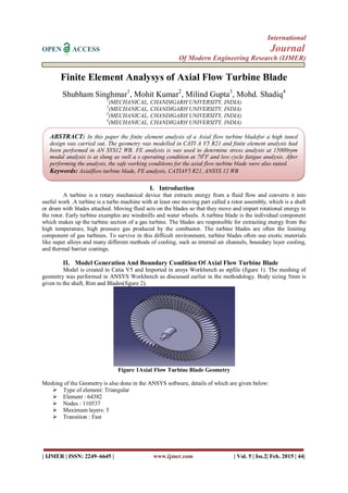
- 1. International OPEN ACCESS Journal Of Modern Engineering Research (IJMER) | IJMER | ISSN: 2249–6645 | www.ijmer.com | Vol. 5 | Iss.2| Feb. 2015 | 44| Finite Element Analysys of Axial Flow Turbine Blade Shubham Singhmar1 , Mohit Kumar2 , Milind Gupta3 , Mohd. Shadiq4 1 (MECHANICAL, CHANDIGARH UNIVERSITY, INDIA) 2 (MECHANICAL, CHANDIGARH UNIVERSITY, INDIA) 3 (MECHANICAL, CHANDIGARH UNIVERSITY, INDIA) 4 (MECHANICAL, CHANDIGARH UNIVERSITY, INDIA) I. Introduction A turbine is a rotary mechanical device that extracts energy from a fluid flow and converts it into useful work .A turbine is a turbo machine with at least one moving part called a rotor assembly, which is a shaft or drum with blades attached. Moving fluid acts on the blades so that they move and impart rotational energy to the rotor. Early turbine examples are windmills and water wheels. A turbine blade is the individual component which makes up the turbine section of a gas turbine. The blades are responsible for extracting energy from the high temperature, high pressure gas produced by the combustor. The turbine blades are often the limiting component of gas turbines. To survive in this difficult environment, turbine blades often use exotic materials like super alloys and many different methods of cooling, such as internal air channels, boundary layer cooling, and thermal barrier coatings. II. Model Generation And Boundary Condition Of Axial Flow Turbine Blade Model is created in Catia V5 and Imported in ansys Workbench as stpfile (figure 1). The meshing of geometry was performed in ANSYS Workbench as discussed earlier in the methodology. Body sizing 5mm is given to the shaft, Rim and Blades(figure 2). Figure 1Axial Flow Turbine Blade Geometry Meshing of the Geometry is also done in the ANSYS software, details of which are given below: Type of element: Triangular Element : 64382 Nodes : 110537 Maximum layers: 5 Transition : Fast ABSTRACT: In this paper the finite element analysis of a Axial flow turbine bladefor a high tuned design was carried out. The geometry was modelled in CATI A V5 R21 and finite element analysis had been performed in AN SYS12 WB. FE analysis is was used to determine stress analysis at 15000rpm modal analysis is at slung as well a s operating condition at 700 F and low cycle fatigue analysis. After performing the analysis, the safe working conditions for the axial flow turbine blade were also stated. Keywords: Axialflow turbine blade, FE analysis, CATIAV5 R21, ANSYS 12 WB
- 2. Finite Element Analysys of Axial Flow Turbine Blade | IJMER | ISSN: 2249–6645 | www.ijmer.com | Vol. 5 | Iss.2| Feb. 2015 | 45| Figure 2 Meshing of Axial Flow Turbine Blade Geometry III. Material Properties To survive in this difficult environment, turbine blades often use exotic materials like super alloys and many different methods of cooling, such as internal air channels, boundary layer cooling, and thermal barrier coatings. Load and Boundary Conditions As per the problem statement the Rotational velocity is applied to all bodies is 15000 RPM , Fixing condition is applied as Remote displacement that is Rotation in Z direction is free and other Degree of freedom is fixed. This remote displacement support is applied both ends of the shaft. Pressure load is applied on the faces of the all bodies that is 0.9 bar. Using these boundary conditions static structural analysis is performed. The temperature is applied in the shat and bottom of the rim as 30 o C. Temperature is applied in outer rim and all blades as 300o C .Using these boundary conditions Transient Thermal analysis performed .To find out the thermal stress thermal to structural analysis performed. FIGURE 3 REMOTE DISPLACEMENT FIGURE 4 ROTATIONAL VELOCITY Temp/Properties 30 o C 200 o C 350 o C 650 o C Young’s Modulus(E)GPa 207.7 194.6 186.5 170.6 Ultimate Strength (σu)MPa 1240 1161 1201 1067 Yield Strength (σy)MPa 1035 969 1002 890 Thermal Conductivity (K) W/mk 11.7 14.90 16.27 19.73 Thermal Expansion (α) e-6/o C 12.42 13.32 13.95 14.76 Specific Heat (Cp)J/kg k 418.6 460.5 502.4 586.2 Density (ρ)Kg/m3 8220
- 3. Finite Element Analysys of Axial Flow Turbine Blade | IJMER | ISSN: 2249–6645 | www.ijmer.com | Vol. 5 | Iss.2| Feb. 2015 | 46| FIGURE 5 PRESSURES ANALYSIS 1. Static Structural analysis 2. Transient Thermal analysis 3. Thermal to Structural coupled analysis 4. Fatigue Analysis 5. Modal analysis At 0 RPM 6. Model analysis At 15000 RPM IV. Solutions After solving the model in ANSYS, following results are obtained: Figure 3 STRESS PLOT Figure 4. DISPLACEMENT PLOT Figure 5THERMAL PLOT Figure 6TERMAL STRESS PLOT
- 4. Finite Element Analysys of Axial Flow Turbine Blade | IJMER | ISSN: 2249–6645 | www.ijmer.com | Vol. 5 | Iss.2| Feb. 2015 | 47| Figure 7SAFETY FACTOR Figure 8LIFE PLOT FIGURE12 DAMAGE PLOT Figure 13 MODE SHAPE 1 AT 0 RPM Figure 14 MODE SHAPE 2 AT 0 RPM Figure 15MODE SHAPE 1 AT 15000 RPM
- 5. Finite Element Analysys of Axial Flow Turbine Blade | IJMER | ISSN: 2249–6645 | www.ijmer.com | Vol. 5 | Iss.2| Feb. 2015 | 48| Figure 16 MODE SHAPE 2 AT 15000 RPM V. Conclusions From the above static structural analysis we found that maximum stress is 160.41Mpa, in the thermal to structural analysis the maximum stress is 847.33Mpa , the material yield strength is 1002 Mpa , comparing with this value the stress values are less . From this we conclude that The Axial Turbine Blade is safe. REFERENCES [1]. Yahya S.M., Turbines, Compressors and Fans , ISBN 9780070597709 [2]. Frank Bleier, Fan Handbook : Selection , Application and design, ISBN 978-0070059337 [3]. ANSI/AMCA Standard 99-2412 Impeller Diameter and Outlet Area for Centrifugal Fan [4]. Centrifugal Fans , John Henry Kinealy , Nabu Press ISBN 9781246058086 [5]. o.c. Zeinkiewicz , R.L. Taylor , The Finite Element Method , Fifth Edition , ISBN 0750650559 [6]. Joseph C. Slater , Wright Finite Element Method : An Easily extensible research-oriented finite element code , April 5,2004 [7]. S.S. Rao ,The Finite Element Method in Engineering , Fourth Edition , ISBN 0750678283 [8]. Abdullah O I, and Schlattmann J (2012). Stress Analysis of Axial Flow Fan, Adv. Theor. Appl. Mech, vol 5(6), 263–275. [9]. Anderson J D (2001). Fundamentals of aerodynamics,McGraw-Hill, New York, vol 2.