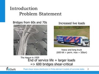
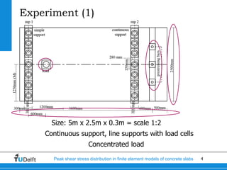
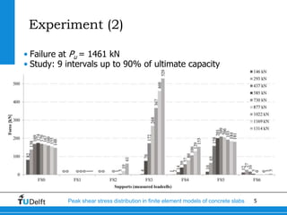
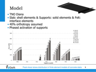
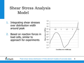
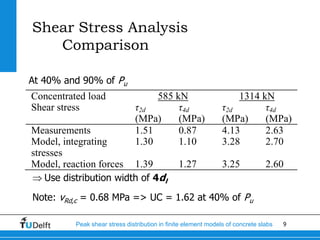
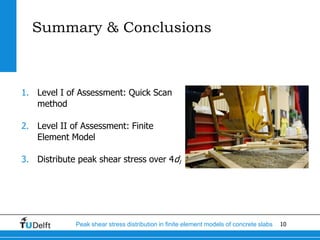
02-09-2013
Challenge the future
Delft
University of
Technology
Peak shear stress distribution
in finite element models of concrete slabs
Eva Lantsoght, Ane de Boer, Cor van der Veen, Joost Walraven
2Peak shear stress distribution in finite element models of concrete slabs
Introduction
Problem Statement
Bridges from 60s and 70s
The Hague in 1959
Increased live loads
heavy and long truck
(600 kN > perm. max = 50ton)
End of service life + larger loads
=> 600 bridges shear-critical
3Peak shear stress distribution in finite element models of concrete slabs
Introduction
Shear assessment strategy
• Level I: Quick Scan sheet
• Fast, simple and conservative spreadsheet
• Unity check: loads/capacity
• Level II: Finite Element Analysis
• Shear stress distribution over support
• Peak shear stress: distribute over which width?
4Peak shear stress distribution in finite element models of concrete slabs
Experiment (1)
Size: 5m x 2.5m x 0.3m = scale 1:2
Continuous support, line supports with load cells
Concentrated load
5Peak shear stress distribution in finite element models of concrete slabs
Experiment (2)
• Failure at Pu = 1461 kN
• Study: 9 intervals up to 90% of ultimate capacity
6Peak shear stress distribution in finite element models of concrete slabs
Model
• TNO Diana
• Slab: shell elements & Supports: solid elements & Felt:
interface elements
• 40% orthotropy assumed
• Phased activation of supports
7Peak shear stress distribution in finite element models of concrete slabs
Shear Stress Analysis
Experiment
• Assume force distributed
constantly per load cell
• Example: P = 1314 kN
• Total force over 2dl
• Resulting shear stress
,2
86 mm
3 2 4 580 kN
358 mm
tot dF FS FS FS
,2
2 2 2
580 kN
4.13 MPa
2 2 265 mm
tot d
d
l
F
d
8Peak shear stress distribution in finite element models of concrete slabs
Shear Stress Analysis
Model
1. Integrating shear stresses
over distribution width
around peak
2. Based on reaction forces in
load cells, similar to
approach for experiments
9Peak shear stress distribution in finite element models of concrete slabs
Shear Stress Analysis
Comparison
Concentrated load 585 kN 1314 kN
Shear stress τ2d
(MPa)
τ4d
(MPa)
τ2d
(MPa)
τ4d
(MPa)
Measurements 1.51 0.87 4.13 2.63
Model, integrating
stresses
1.30 1.10 3.28 2.70
Model, reaction forces 1.39 1.27 3.25 2.60
Use distribution width of 4dl
Note: vRd,c = 0.68 MPa => UC = 1.62 at 40% of Pu
At 40% and 90% of Pu
10Peak shear stress distribution in finite element models of concrete slabs
Summary & Conclusions
1. Level I of Assessment: Quick Scan
method
2. Level II of Assessment: Finite
Element Model
3. Distribute peak shear stress over 4dl
11Peak shear stress distribution in finite element models of concrete slabs
Contact:
Eva Lantsoght
E.O.L.Lantsoght@tudelft.nl
+31(0)152787449

Peak shear stress distribution in finite element models of concrete slabs

  • 1.
    02-09-2013 Challenge the future Delft Universityof Technology Peak shear stress distribution in finite element models of concrete slabs Eva Lantsoght, Ane de Boer, Cor van der Veen, Joost Walraven
  • 2.
    2Peak shear stressdistribution in finite element models of concrete slabs Introduction Problem Statement Bridges from 60s and 70s The Hague in 1959 Increased live loads heavy and long truck (600 kN > perm. max = 50ton) End of service life + larger loads => 600 bridges shear-critical
  • 3.
    3Peak shear stressdistribution in finite element models of concrete slabs Introduction Shear assessment strategy • Level I: Quick Scan sheet • Fast, simple and conservative spreadsheet • Unity check: loads/capacity • Level II: Finite Element Analysis • Shear stress distribution over support • Peak shear stress: distribute over which width?
  • 4.
    4Peak shear stressdistribution in finite element models of concrete slabs Experiment (1) Size: 5m x 2.5m x 0.3m = scale 1:2 Continuous support, line supports with load cells Concentrated load
  • 5.
    5Peak shear stressdistribution in finite element models of concrete slabs Experiment (2) • Failure at Pu = 1461 kN • Study: 9 intervals up to 90% of ultimate capacity
  • 6.
    6Peak shear stressdistribution in finite element models of concrete slabs Model • TNO Diana • Slab: shell elements & Supports: solid elements & Felt: interface elements • 40% orthotropy assumed • Phased activation of supports
  • 7.
    7Peak shear stressdistribution in finite element models of concrete slabs Shear Stress Analysis Experiment • Assume force distributed constantly per load cell • Example: P = 1314 kN • Total force over 2dl • Resulting shear stress ,2 86 mm 3 2 4 580 kN 358 mm tot dF FS FS FS ,2 2 2 2 580 kN 4.13 MPa 2 2 265 mm tot d d l F d
  • 8.
    8Peak shear stressdistribution in finite element models of concrete slabs Shear Stress Analysis Model 1. Integrating shear stresses over distribution width around peak 2. Based on reaction forces in load cells, similar to approach for experiments
  • 9.
    9Peak shear stressdistribution in finite element models of concrete slabs Shear Stress Analysis Comparison Concentrated load 585 kN 1314 kN Shear stress τ2d (MPa) τ4d (MPa) τ2d (MPa) τ4d (MPa) Measurements 1.51 0.87 4.13 2.63 Model, integrating stresses 1.30 1.10 3.28 2.70 Model, reaction forces 1.39 1.27 3.25 2.60 Use distribution width of 4dl Note: vRd,c = 0.68 MPa => UC = 1.62 at 40% of Pu At 40% and 90% of Pu
  • 10.
    10Peak shear stressdistribution in finite element models of concrete slabs Summary & Conclusions 1. Level I of Assessment: Quick Scan method 2. Level II of Assessment: Finite Element Model 3. Distribute peak shear stress over 4dl
  • 11.
    11Peak shear stressdistribution in finite element models of concrete slabs Contact: Eva Lantsoght E.O.L.Lantsoght@tudelft.nl +31(0)152787449