SlideShare a Scribd company logo
1 of 39
Transistors
Different types and sizes
BJT (PNP) Electrical Diagram
First Transistor
Modern Electronics
FET and BJT Transistor
TRANSISTOR
•Transistor is a device which transfers applied
signal from one type of resister to other type, for
example signal can be transferred from low
resistor to high or from high resistor to low
resistor. By combination of two words transfer
and resister it is called “Transistor” (Transfer
+resistor).
•John Bardeen, Walter Brattain & William
Schokley invented Transistor in 1947
CLASSIFICATION OF TRANSISTOR
BJT (Bipolar Junction Transistor)
•The BJT has three portions inside it, namely the
emitter, the base and the collector, denoted by E,
B and C respectively.
•Emitter: Emitter is a portion of transistor through
which charge carriers enter into it.
•Base: Base is a portion of transistor which
controls the flow of charge carriers between
emitter and collector.
•Collector: Collector is a portion of transistor at
which charge carriers are collected.
BJT (Bipolar Junction Transistor)
• BJT can be classified into two types:
1. npn transistor
2. pnp transistor
In n-p-n type a thin layer of p-type is sandwiched
between two layers of n-type semiconductor.
BJT (Bipolar Junction Transistor)
•
•In p-n-p type, a thin layer of n-type is
sandwiched between two layers of p type
semiconductor.
BJT (Bipolar Junction Transistor)
•In BJT, the emitter layer is heavily doped, the
base lightly doped, and the collector only lightly
doped.
•The outer layers have widths much greater than
the sandwiched p- or n-type material.
•Area and doping profile of these regions are
given as:
Area profile: C>E>B
Doping profile: E>C>B
Operation of Transistor
• Operation of transistor is dependent on the
biasing of emitter and collection junction.
• As we know there are two junction in the BJT and
each junction can biased in two ways either
forward bias or reverse bias.
• It means operation of BJT can be dependent on
following four situations:
Operation of Transistor
• Emitter junction is forward based and collector
junction is reversed bias. In this situation BJT will be
called in active region and BJT will be used as an
amplifier.
• Emitter junction is forward base and collector
junction is also forward bias. In this situation BJT will
be called in saturation region and it will be used as a
switch.
Operation of Transistor
• Emitter junction is reverse bias and collector junction
is also reversed bias in this situation BJT will be called
in Cut off Region and it will be used as switch.
• Emitter junction is reversed bias and collector
junction is forward bias. In this situation BJT will be
called reversed active and there is no use of this type
of biasing.
Operation of Transistor in Active
Region
• To operate BJT in active region JEB (emitter base
junction) must be forward biased and JCB (collector
base junction) must be reverse biased.
Operation of Transistor in Active
Region
• JEB is forward biased by the battery VEE by which the
depletion region will decrease and a majority carrier
flow will occur from emitter to base giving current
Imajority or IE.
• So, Here, IeE is current due to electrons of emitter
region and IhB is current due to holes in base region.
Operation of Transistor in Active
Region
• In base region there is recombination between
electrons and holes due to which base current is
obtained. As number of holes in base is very small,
base current is very small.
• JCB is reverse biased by VCC. So collector current is due
to flow of minority charge carriers from both sides of
the junction. In base minority carriers are electrons
left after recombination and in collector minority
carriers are holes. So,
• Directions of all terminal currents are shown in figure
and it is clear that,
Operation of Transistor in Active
Region
• Directions of all terminal currents are shown in figure
and it is clear that,
Transistor Configurations
• We know that, transistor can be used as an
amplifier. For an amplifier, two terminals are
required to supply the weak signal and two
terminals to collect the amplified signal.
• Thus four terminals are required but a transistor
is said to have only three terminals Therefore,
one terminal is used common for both input
and output.
Transistor Configurations
This gives rise to three different combinations.
• Common base configuration (CB)
• Common emitter configuration (CE)
• Common collector configuration (CC)
Transistor Configurations
Common Collector configuration (CC)
Input V/I Characteristics of CB Configuration
• It is graph between input current (IE) and input
voltage (VEB) at constant output voltage (VCB).
This graph is drawn for active region of BJT.
Input V/I Characteristics of CB Configuration
• By keeping constant VCB, when forward bias at emitter base junction is
increased then graph between IB and VEB is similar to forward
characteristics of pn junction diode. If this graph is again drawn for some
higher value of VCB a similar graph is obtained with reduced knee voltage.
Output V/I Characteristics of CB Configuration
• It is graph between output current IC and
output voltage VCE at constant input current IE.
This graph is drawn for all three operating
regions of BJT.
• To draw the graph in active region equation of
output current,
Output V/I Characteristics of CB Configuration
• For given and IE, IC is dependent only on I0 which is slightly
dependent on VCB. So, graph of active region is almost
independent of VCB.
• When the transistor is switched from active to saturation
region, a large change in collector current for very small
forward bias voltage at collector to base junction is obtained
in negative direction.
• When both the junctions are reverse biased, a very small
collector current is obtained which is close to horizontal axis.
Current Gain of CB Configuration
•In active region equation of
output current can be give as,
Here I0 is reverse saturation current in CB configuration also
written as ICBO
So,
ICBO can be neglected as compared to IC and IE
Then,
Here, α is called dc current of CB Configuration and its value
is around 0.99
Output V/I Characteristics of CB Configuration
Input V/I Characteristics of CE Configuration
•It is graph between input current (IB) and input voltage
(VBE) at constant output voltage (VCE). This graph is drawn
for active region of BJT.
•By keeping constant VCE, when forward bias at emitter
base junction is increased then graph between IE and VBE
is similar to forward characteristics of pn junction diode.
Input V/I Characteristics of CE Configuration
If this graph is again drawn for some higher value of VCE a similar
graph is obtained with increased knee voltage. This is due to
reduction in IB on increasing reverse bias at collector base
junction.
Input V/I Characteristics of CE Configuration
Output V/I Characteristics of CE Configuration
•It is graph between output current IC and
output voltage VCE at constant input current IB.
This graph is drawn for all three operating
regions of BJT.
•To draw the graph in active region equation of
output current,
Output V/I Characteristics of CE Configuration
For given and IB, IC is dependent on ( +1)I0
which is more dependent on VCE than in case of
CB configuration. So, graph of active region
has some slope showing change in IC on
changing VCE
Output V/I Characteristics of CE Configuration
Current Gain in CE Configuration
• Expression of output current Ic can be given as,
Ic
= α IE + ICBO
= α (IC + IB )+ ICBO
IC (1- α)= α IB + ICBO
Let,
then,
So, Ic
= βIB + (β +1)ICBO
Current Gain in CE Configuration
• β is called dc current gain of CE configuration.
• The second term of equation, Ic
= βIB + (β +1)ICBO
is reverse saturation current in CE configuration
and represented as ICEO.
So, ICEO
= (β +1)ICBO
Ans 1
Ans 2
Ans 3
Therefore emitter current, IE =IC + IB =1010+20=1030µA =1.03mA
Comparison of Different Configurations

More Related Content

Similar to unit 2 part1 (1).pptx

Similar to unit 2 part1 (1).pptx (20)

Chapter 4 bjt
Chapter 4 bjtChapter 4 bjt
Chapter 4 bjt
 
Bipolar junction transisitors.ppt
Bipolar junction transisitors.pptBipolar junction transisitors.ppt
Bipolar junction transisitors.ppt
 
Transistor Configuration
Transistor Configuration Transistor Configuration
Transistor Configuration
 
BIPOLAR JUNCTION TRANSISTOR
BIPOLAR JUNCTION TRANSISTORBIPOLAR JUNCTION TRANSISTOR
BIPOLAR JUNCTION TRANSISTOR
 
Chapter 6: Bipolar Junction Transistors (BJTs)
Chapter 6: Bipolar Junction Transistors (BJTs)Chapter 6: Bipolar Junction Transistors (BJTs)
Chapter 6: Bipolar Junction Transistors (BJTs)
 
Shubham shakya BJT Basic in Hindi
Shubham shakya BJT Basic in HindiShubham shakya BJT Basic in Hindi
Shubham shakya BJT Basic in Hindi
 
bjt1.ppt
bjt1.pptbjt1.ppt
bjt1.ppt
 
viva ppt2.pptx
viva ppt2.pptxviva ppt2.pptx
viva ppt2.pptx
 
viva ppt2.pptx
viva ppt2.pptxviva ppt2.pptx
viva ppt2.pptx
 
BJT.ppt
BJT.pptBJT.ppt
BJT.ppt
 
BJT.....pdf
BJT.....pdfBJT.....pdf
BJT.....pdf
 
Unit II.ppt
Unit II.pptUnit II.ppt
Unit II.ppt
 
Transistor configurations
Transistor configurationsTransistor configurations
Transistor configurations
 
EDCbijuntiiontransitorlecturesnist1.pptx
EDCbijuntiiontransitorlecturesnist1.pptxEDCbijuntiiontransitorlecturesnist1.pptx
EDCbijuntiiontransitorlecturesnist1.pptx
 
Unit 2.pptx
Unit  2.pptxUnit  2.pptx
Unit 2.pptx
 
Aec ppt2
Aec ppt2Aec ppt2
Aec ppt2
 
Aec ppt2
Aec ppt2Aec ppt2
Aec ppt2
 
AIDS Unit_5.pptx
AIDS Unit_5.pptxAIDS Unit_5.pptx
AIDS Unit_5.pptx
 
Unit 3
Unit 3Unit 3
Unit 3
 
CLIPPER AND CLAMPER AND BIPOLAR JUNCTION TRANSISTER AMPLIFIER
CLIPPER AND CLAMPER AND BIPOLAR JUNCTION TRANSISTER AMPLIFIERCLIPPER AND CLAMPER AND BIPOLAR JUNCTION TRANSISTER AMPLIFIER
CLIPPER AND CLAMPER AND BIPOLAR JUNCTION TRANSISTER AMPLIFIER
 

Recently uploaded

CCS355 Neural Networks & Deep Learning Unit 1 PDF notes with Question bank .pdf
CCS355 Neural Networks & Deep Learning Unit 1 PDF notes with Question bank .pdfCCS355 Neural Networks & Deep Learning Unit 1 PDF notes with Question bank .pdf
CCS355 Neural Networks & Deep Learning Unit 1 PDF notes with Question bank .pdfAsst.prof M.Gokilavani
 
Software and Systems Engineering Standards: Verification and Validation of Sy...
Software and Systems Engineering Standards: Verification and Validation of Sy...Software and Systems Engineering Standards: Verification and Validation of Sy...
Software and Systems Engineering Standards: Verification and Validation of Sy...VICTOR MAESTRE RAMIREZ
 
Internship report on mechanical engineering
Internship report on mechanical engineeringInternship report on mechanical engineering
Internship report on mechanical engineeringmalavadedarshan25
 
Effects of rheological properties on mixing
Effects of rheological properties on mixingEffects of rheological properties on mixing
Effects of rheological properties on mixingviprabot1
 
CCS355 Neural Network & Deep Learning UNIT III notes and Question bank .pdf
CCS355 Neural Network & Deep Learning UNIT III notes and Question bank .pdfCCS355 Neural Network & Deep Learning UNIT III notes and Question bank .pdf
CCS355 Neural Network & Deep Learning UNIT III notes and Question bank .pdfAsst.prof M.Gokilavani
 
VICTOR MAESTRE RAMIREZ - Planetary Defender on NASA's Double Asteroid Redirec...
VICTOR MAESTRE RAMIREZ - Planetary Defender on NASA's Double Asteroid Redirec...VICTOR MAESTRE RAMIREZ - Planetary Defender on NASA's Double Asteroid Redirec...
VICTOR MAESTRE RAMIREZ - Planetary Defender on NASA's Double Asteroid Redirec...VICTOR MAESTRE RAMIREZ
 
Concrete Mix Design - IS 10262-2019 - .pptx
Concrete Mix Design - IS 10262-2019 - .pptxConcrete Mix Design - IS 10262-2019 - .pptx
Concrete Mix Design - IS 10262-2019 - .pptxKartikeyaDwivedi3
 
Risk Assessment For Installation of Drainage Pipes.pdf
Risk Assessment For Installation of Drainage Pipes.pdfRisk Assessment For Installation of Drainage Pipes.pdf
Risk Assessment For Installation of Drainage Pipes.pdfROCENODodongVILLACER
 
What are the advantages and disadvantages of membrane structures.pptx
What are the advantages and disadvantages of membrane structures.pptxWhat are the advantages and disadvantages of membrane structures.pptx
What are the advantages and disadvantages of membrane structures.pptxwendy cai
 
GDSC ASEB Gen AI study jams presentation
GDSC ASEB Gen AI study jams presentationGDSC ASEB Gen AI study jams presentation
GDSC ASEB Gen AI study jams presentationGDSCAESB
 
DATA ANALYTICS PPT definition usage example
DATA ANALYTICS PPT definition usage exampleDATA ANALYTICS PPT definition usage example
DATA ANALYTICS PPT definition usage examplePragyanshuParadkar1
 
IVE Industry Focused Event - Defence Sector 2024
IVE Industry Focused Event - Defence Sector 2024IVE Industry Focused Event - Defence Sector 2024
IVE Industry Focused Event - Defence Sector 2024Mark Billinghurst
 
Gurgaon ✡️9711147426✨Call In girls Gurgaon Sector 51 escort service
Gurgaon ✡️9711147426✨Call In girls Gurgaon Sector 51 escort serviceGurgaon ✡️9711147426✨Call In girls Gurgaon Sector 51 escort service
Gurgaon ✡️9711147426✨Call In girls Gurgaon Sector 51 escort servicejennyeacort
 
Sachpazis Costas: Geotechnical Engineering: A student's Perspective Introduction
Sachpazis Costas: Geotechnical Engineering: A student's Perspective IntroductionSachpazis Costas: Geotechnical Engineering: A student's Perspective Introduction
Sachpazis Costas: Geotechnical Engineering: A student's Perspective IntroductionDr.Costas Sachpazis
 
Oxy acetylene welding presentation note.
Oxy acetylene welding presentation note.Oxy acetylene welding presentation note.
Oxy acetylene welding presentation note.eptoze12
 
Call Girls Narol 7397865700 Independent Call Girls
Call Girls Narol 7397865700 Independent Call GirlsCall Girls Narol 7397865700 Independent Call Girls
Call Girls Narol 7397865700 Independent Call Girlsssuser7cb4ff
 
Introduction to Machine Learning Unit-3 for II MECH
Introduction to Machine Learning Unit-3 for II MECHIntroduction to Machine Learning Unit-3 for II MECH
Introduction to Machine Learning Unit-3 for II MECHC Sai Kiran
 
An experimental study in using natural admixture as an alternative for chemic...
An experimental study in using natural admixture as an alternative for chemic...An experimental study in using natural admixture as an alternative for chemic...
An experimental study in using natural admixture as an alternative for chemic...Chandu841456
 

Recently uploaded (20)

CCS355 Neural Networks & Deep Learning Unit 1 PDF notes with Question bank .pdf
CCS355 Neural Networks & Deep Learning Unit 1 PDF notes with Question bank .pdfCCS355 Neural Networks & Deep Learning Unit 1 PDF notes with Question bank .pdf
CCS355 Neural Networks & Deep Learning Unit 1 PDF notes with Question bank .pdf
 
young call girls in Green Park🔝 9953056974 🔝 escort Service
young call girls in Green Park🔝 9953056974 🔝 escort Serviceyoung call girls in Green Park🔝 9953056974 🔝 escort Service
young call girls in Green Park🔝 9953056974 🔝 escort Service
 
Software and Systems Engineering Standards: Verification and Validation of Sy...
Software and Systems Engineering Standards: Verification and Validation of Sy...Software and Systems Engineering Standards: Verification and Validation of Sy...
Software and Systems Engineering Standards: Verification and Validation of Sy...
 
Internship report on mechanical engineering
Internship report on mechanical engineeringInternship report on mechanical engineering
Internship report on mechanical engineering
 
Effects of rheological properties on mixing
Effects of rheological properties on mixingEffects of rheological properties on mixing
Effects of rheological properties on mixing
 
CCS355 Neural Network & Deep Learning UNIT III notes and Question bank .pdf
CCS355 Neural Network & Deep Learning UNIT III notes and Question bank .pdfCCS355 Neural Network & Deep Learning UNIT III notes and Question bank .pdf
CCS355 Neural Network & Deep Learning UNIT III notes and Question bank .pdf
 
VICTOR MAESTRE RAMIREZ - Planetary Defender on NASA's Double Asteroid Redirec...
VICTOR MAESTRE RAMIREZ - Planetary Defender on NASA's Double Asteroid Redirec...VICTOR MAESTRE RAMIREZ - Planetary Defender on NASA's Double Asteroid Redirec...
VICTOR MAESTRE RAMIREZ - Planetary Defender on NASA's Double Asteroid Redirec...
 
Concrete Mix Design - IS 10262-2019 - .pptx
Concrete Mix Design - IS 10262-2019 - .pptxConcrete Mix Design - IS 10262-2019 - .pptx
Concrete Mix Design - IS 10262-2019 - .pptx
 
🔝9953056974🔝!!-YOUNG call girls in Rajendra Nagar Escort rvice Shot 2000 nigh...
🔝9953056974🔝!!-YOUNG call girls in Rajendra Nagar Escort rvice Shot 2000 nigh...🔝9953056974🔝!!-YOUNG call girls in Rajendra Nagar Escort rvice Shot 2000 nigh...
🔝9953056974🔝!!-YOUNG call girls in Rajendra Nagar Escort rvice Shot 2000 nigh...
 
Risk Assessment For Installation of Drainage Pipes.pdf
Risk Assessment For Installation of Drainage Pipes.pdfRisk Assessment For Installation of Drainage Pipes.pdf
Risk Assessment For Installation of Drainage Pipes.pdf
 
What are the advantages and disadvantages of membrane structures.pptx
What are the advantages and disadvantages of membrane structures.pptxWhat are the advantages and disadvantages of membrane structures.pptx
What are the advantages and disadvantages of membrane structures.pptx
 
GDSC ASEB Gen AI study jams presentation
GDSC ASEB Gen AI study jams presentationGDSC ASEB Gen AI study jams presentation
GDSC ASEB Gen AI study jams presentation
 
DATA ANALYTICS PPT definition usage example
DATA ANALYTICS PPT definition usage exampleDATA ANALYTICS PPT definition usage example
DATA ANALYTICS PPT definition usage example
 
IVE Industry Focused Event - Defence Sector 2024
IVE Industry Focused Event - Defence Sector 2024IVE Industry Focused Event - Defence Sector 2024
IVE Industry Focused Event - Defence Sector 2024
 
Gurgaon ✡️9711147426✨Call In girls Gurgaon Sector 51 escort service
Gurgaon ✡️9711147426✨Call In girls Gurgaon Sector 51 escort serviceGurgaon ✡️9711147426✨Call In girls Gurgaon Sector 51 escort service
Gurgaon ✡️9711147426✨Call In girls Gurgaon Sector 51 escort service
 
Sachpazis Costas: Geotechnical Engineering: A student's Perspective Introduction
Sachpazis Costas: Geotechnical Engineering: A student's Perspective IntroductionSachpazis Costas: Geotechnical Engineering: A student's Perspective Introduction
Sachpazis Costas: Geotechnical Engineering: A student's Perspective Introduction
 
Oxy acetylene welding presentation note.
Oxy acetylene welding presentation note.Oxy acetylene welding presentation note.
Oxy acetylene welding presentation note.
 
Call Girls Narol 7397865700 Independent Call Girls
Call Girls Narol 7397865700 Independent Call GirlsCall Girls Narol 7397865700 Independent Call Girls
Call Girls Narol 7397865700 Independent Call Girls
 
Introduction to Machine Learning Unit-3 for II MECH
Introduction to Machine Learning Unit-3 for II MECHIntroduction to Machine Learning Unit-3 for II MECH
Introduction to Machine Learning Unit-3 for II MECH
 
An experimental study in using natural admixture as an alternative for chemic...
An experimental study in using natural admixture as an alternative for chemic...An experimental study in using natural admixture as an alternative for chemic...
An experimental study in using natural admixture as an alternative for chemic...
 

unit 2 part1 (1).pptx

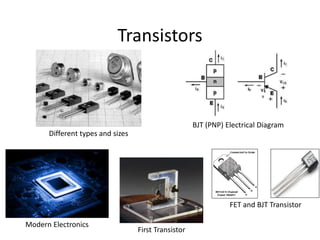
  • 1. Transistors Different types and sizes BJT (PNP) Electrical Diagram First Transistor Modern Electronics FET and BJT Transistor
  • 2. TRANSISTOR •Transistor is a device which transfers applied signal from one type of resister to other type, for example signal can be transferred from low resistor to high or from high resistor to low resistor. By combination of two words transfer and resister it is called “Transistor” (Transfer +resistor). •John Bardeen, Walter Brattain & William Schokley invented Transistor in 1947
  • 4. BJT (Bipolar Junction Transistor) •The BJT has three portions inside it, namely the emitter, the base and the collector, denoted by E, B and C respectively. •Emitter: Emitter is a portion of transistor through which charge carriers enter into it. •Base: Base is a portion of transistor which controls the flow of charge carriers between emitter and collector. •Collector: Collector is a portion of transistor at which charge carriers are collected.
  • 5. BJT (Bipolar Junction Transistor) • BJT can be classified into two types: 1. npn transistor 2. pnp transistor In n-p-n type a thin layer of p-type is sandwiched between two layers of n-type semiconductor.
  • 6. BJT (Bipolar Junction Transistor) • •In p-n-p type, a thin layer of n-type is sandwiched between two layers of p type semiconductor.
  • 7. BJT (Bipolar Junction Transistor) •In BJT, the emitter layer is heavily doped, the base lightly doped, and the collector only lightly doped. •The outer layers have widths much greater than the sandwiched p- or n-type material. •Area and doping profile of these regions are given as: Area profile: C>E>B Doping profile: E>C>B
  • 8. Operation of Transistor • Operation of transistor is dependent on the biasing of emitter and collection junction. • As we know there are two junction in the BJT and each junction can biased in two ways either forward bias or reverse bias. • It means operation of BJT can be dependent on following four situations:
  • 9. Operation of Transistor • Emitter junction is forward based and collector junction is reversed bias. In this situation BJT will be called in active region and BJT will be used as an amplifier. • Emitter junction is forward base and collector junction is also forward bias. In this situation BJT will be called in saturation region and it will be used as a switch.
  • 10. Operation of Transistor • Emitter junction is reverse bias and collector junction is also reversed bias in this situation BJT will be called in Cut off Region and it will be used as switch. • Emitter junction is reversed bias and collector junction is forward bias. In this situation BJT will be called reversed active and there is no use of this type of biasing.
  • 11. Operation of Transistor in Active Region • To operate BJT in active region JEB (emitter base junction) must be forward biased and JCB (collector base junction) must be reverse biased.
  • 12. Operation of Transistor in Active Region • JEB is forward biased by the battery VEE by which the depletion region will decrease and a majority carrier flow will occur from emitter to base giving current Imajority or IE. • So, Here, IeE is current due to electrons of emitter region and IhB is current due to holes in base region.
  • 13. Operation of Transistor in Active Region • In base region there is recombination between electrons and holes due to which base current is obtained. As number of holes in base is very small, base current is very small. • JCB is reverse biased by VCC. So collector current is due to flow of minority charge carriers from both sides of the junction. In base minority carriers are electrons left after recombination and in collector minority carriers are holes. So, • Directions of all terminal currents are shown in figure and it is clear that,
  • 14. Operation of Transistor in Active Region • Directions of all terminal currents are shown in figure and it is clear that,
  • 15. Transistor Configurations • We know that, transistor can be used as an amplifier. For an amplifier, two terminals are required to supply the weak signal and two terminals to collect the amplified signal. • Thus four terminals are required but a transistor is said to have only three terminals Therefore, one terminal is used common for both input and output.
  • 16. Transistor Configurations This gives rise to three different combinations. • Common base configuration (CB) • Common emitter configuration (CE) • Common collector configuration (CC)
  • 19. Input V/I Characteristics of CB Configuration • It is graph between input current (IE) and input voltage (VEB) at constant output voltage (VCB). This graph is drawn for active region of BJT.
  • 20. Input V/I Characteristics of CB Configuration • By keeping constant VCB, when forward bias at emitter base junction is increased then graph between IB and VEB is similar to forward characteristics of pn junction diode. If this graph is again drawn for some higher value of VCB a similar graph is obtained with reduced knee voltage.
  • 21. Output V/I Characteristics of CB Configuration • It is graph between output current IC and output voltage VCE at constant input current IE. This graph is drawn for all three operating regions of BJT. • To draw the graph in active region equation of output current,
  • 22. Output V/I Characteristics of CB Configuration • For given and IE, IC is dependent only on I0 which is slightly dependent on VCB. So, graph of active region is almost independent of VCB. • When the transistor is switched from active to saturation region, a large change in collector current for very small forward bias voltage at collector to base junction is obtained in negative direction. • When both the junctions are reverse biased, a very small collector current is obtained which is close to horizontal axis.
  • 23. Current Gain of CB Configuration •In active region equation of output current can be give as, Here I0 is reverse saturation current in CB configuration also written as ICBO So, ICBO can be neglected as compared to IC and IE Then, Here, α is called dc current of CB Configuration and its value is around 0.99
  • 24. Output V/I Characteristics of CB Configuration
  • 25. Input V/I Characteristics of CE Configuration •It is graph between input current (IB) and input voltage (VBE) at constant output voltage (VCE). This graph is drawn for active region of BJT. •By keeping constant VCE, when forward bias at emitter base junction is increased then graph between IE and VBE is similar to forward characteristics of pn junction diode.
  • 26. Input V/I Characteristics of CE Configuration If this graph is again drawn for some higher value of VCE a similar graph is obtained with increased knee voltage. This is due to reduction in IB on increasing reverse bias at collector base junction.
  • 27. Input V/I Characteristics of CE Configuration
  • 28. Output V/I Characteristics of CE Configuration •It is graph between output current IC and output voltage VCE at constant input current IB. This graph is drawn for all three operating regions of BJT. •To draw the graph in active region equation of output current,
  • 29. Output V/I Characteristics of CE Configuration For given and IB, IC is dependent on ( +1)I0 which is more dependent on VCE than in case of CB configuration. So, graph of active region has some slope showing change in IC on changing VCE
  • 30. Output V/I Characteristics of CE Configuration
  • 31. Output V/I Characteristics of CE Configuration
  • 32. Current Gain in CE Configuration • Expression of output current Ic can be given as, Ic = α IE + ICBO = α (IC + IB )+ ICBO IC (1- α)= α IB + ICBO Let, then, So, Ic = βIB + (β +1)ICBO
  • 33. Current Gain in CE Configuration • β is called dc current gain of CE configuration. • The second term of equation, Ic = βIB + (β +1)ICBO is reverse saturation current in CE configuration and represented as ICEO. So, ICEO = (β +1)ICBO
  • 34.
  • 35. Ans 1
  • 36. Ans 2
  • 37. Ans 3 Therefore emitter current, IE =IC + IB =1010+20=1030µA =1.03mA
  • 38. Comparison of Different Configurations
  • 39. Comparison of Different Configurations

Editor's Notes

  1. (www.dictionary.com) http://captherm.com/semiconductor-cooling/