
Recommended
Recommended
More Related Content
Similar to INSERTS FOR PLASTICSF Lτ = F x LInserts.docx
Similar to INSERTS FOR PLASTICSF Lτ = F x LInserts.docx (20)
More from dirkrplav
More from dirkrplav (20)
Recently uploaded
Recently uploaded (20)
INSERTS FOR PLASTICSF Lτ = F x LInserts.docx
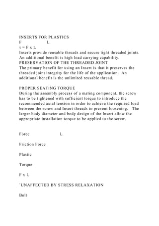
- 1. INSERTS FOR PLASTICS F L τ = F x L Inserts provide reusable threads and secure tight threaded joints. An additional benefit is high load carrying capability. PRESERVATION OF THE THREADED JOINT The primary benefit for using an Insert is that it preserves the threaded joint integrity for the life of the application. An additional benefit is the unlimited reusable thread. PROPER SEATING TORQUE During the assembly process of a mating component, the screw has to be tightened with sufficient torque to introduce the recommended axial tension in order to achieve the required load between the screw and Insert threads to prevent loosening. The larger body diameter and body design of the Insert allow the appropriate installation torque to be applied to the screw. Force L Friction Force Plastic Torque F x L `UNAFFECTED BY STRESS RELAXATION Bolt
- 2. Axial Load (Tension) A common problem with bolted joints in plastic applications is that plastic is susceptible to creep or stress relaxation. Under loads well below the elastic limit, plastics will lose their ability to maintain a load. When this occurs, the threaded connection becomes loose. The brass thread Insert Tension = Torque μ x Bolt ø Torque provides permanent creep resistance for the entire load path of the thread. μ = Coefficient of Friction ≈ 0.2 ENHANCE LOAD CARRYING The load carrying ability of the joint is enhanced by the larger diameter of the Insert as compared to the screw. Inserts are generally twice the diameter of the screw and that increases the shear surface fourfold. Pull-out resistance can further be enhanced by increased Insert length. WHY SPIROL INSERTS? TECHNICAL SUPPORT Since SPIROL’s inception in 1948, we have lead the industry in application engineering support for fastening, joining and
- 3. assembly. Our Inserts are designed to maximize and balance tensile (pull-out) and rotational torque performance. Our Application Engineers have the technical know-how and experience to work together with our customers to develop a cost-effective solution to meet the application requirements. BROAD PRODUCT RANGE/CAPABILITY Our leading edge production technology is suitable to meet all your specific needs for both long and short run requirements at competitive pricing. We offer a broad range of standard products and cost-effective methods of producing special features. Heat/Ultrasonic Self Tapping Press-In Molded-In QUALITY Expansion INSTALLATION SUPPORT We offer installation technical support and installation equipment. Our standardized, time-tested, modular designs are robust, reliable and easily adjustable – allowing simple customization to meet the specific needs of an application. Our comprehensive quality concept encompasses not only product quality, but also quality of design and service. Process control, operational discipline and continuous improvement are the foundation of our mission to exceed our customers' expectations. We are ISO/TS16949, ISO9001 and ISO14001 certified. LOCAL DESIGN, GLOBAL SUPPLY SPIROL has Application Engineers throughout the world to assist you in your designs, supported by state-of-the-art
- 4. manufacturing centers and worldwide stocking facilities to simplify the logistics of delivering your product. The objective is to design an Insert with sufficient torque resistance to accommodate the tightening torque necessary to achieve sufficient axial tension load on the threaded joint to keep it together and prevent loosening, while also achieving pull-out values necessary for the load conditions that the Insert will be exposed to while in service. In general, resistance to torque is a function of diameter and resistance to pull-out is a function of length. These functions, however, are interactive and the challenge for the designer is to achieve the optimum combination of both. Types of Knurls Diamond Straight Helical Post-Mold Installed with Heat or Ultrasonic Installation Knurls are used to increase resistance to torque. Straight knurls, as opposed to diamond knurls, are the preferred design. Coarser knurls increase resistance to torque but they also induce greater stress on the plastic. In addition, the circumference of the Insert determines the knurl pitch so there are practical limitations on knurl design. Helical knurls, in comparison to straight knurls, lower torque resistance but increase axial pull- out resistance. In practice, knurl angles between 30 and 45 degrees have a positive impact on pull-out resistance with a minimal loss of torque value. In some Inserts, different helical knurl bands as well as straight and helical knurls can be combined on the same Insert to achieve an optimum combination of torque and pull-out resistance. Some Inserts are designed with a slightly larger diameter knurl band between two slightly smaller diameter knurl bands on either side separated from the larger knurl band by grooves. With a properly designed Insert and in a hole manufactured as recommended, the plastic will flow over the larger knurl band into the groove and knurls behind the larger knurl band in the
- 5. opposite direction of installation, significantly increasing pull- out resistance. All the plastic above the larger knurl band in effect becomes a shear plane. A head facilitates plastic flow into the upper grooves of the Insert. Finally for best performance, it is essential that the Insert is installed axially square to the hole. This can be facilitated with tapering the Insert or by providing a pilot. Pilots need to be of sufficient length and have a plain, unknurled diameter the same size or slightly smaller than the hole. Self-Tapping Inserts provide the best pull-out resistance for a post-mold installed Insert. The threads are designed with a thin profile to minimize inducing stress into the plastic and a relative coarse pitch to provide the maximum plastic shear surface to resist pull-out. Installation torque is not a problem in that tightening increases the friction between the plastic and threads, and the larger diameter of the external Insert thread increases the frictional surface. Back-out torque performance relies totally on the greater surface area of the external Insert thread and the tension between the threads and plastic. Again, to facilitate installation square to the hole, a good pilot is essential. Installed Flush Expansion Inserts Expansion Inserts are designed for non-critical applications. Ease of installation, not torque and pull-out resistance, is the primary design criteria. Diamond knurls are a cost-effective solution to increase friction enhancing interference between the Insert and the hole wall. 2 Full Threads
- 6. Minimum Torque is an issue to the extent that the Insert must not spin when the bolt is installed. The Insert diameter is designed slightly larger than the hole diameter and slots are provided to reduce interference during Insertion. A generous lead-in is provided to assure straight insertion. Installation of the screw expands the Insert and forces the diamond knurl into the hole wall providing reasonable torque and pull-out resistance for applications with non-demanding load requirements. Press-In Inserts These Inserts are designed to reduce installation cost at a sacrifice of torque and pull-out performance. Helical knurls are used to provide both torque and pull-out resistance and to ensure good plastic flow as the Insert rotates into the hole. Installation torque to achieve sufficient tension between the threads is not a problem in that the helical knurls are designed so that the direction of the installation torque will have the tendency to drive the Insert into the hole — which of course is not possible — as the threaded joint is tightened. A pilot only slightly smaller than the hole and of sufficient length is designed to assure straight Insertion into the hole. Molded-In Inserts This process, although generally more costly in getting the Insert into place than the post-mold installation process, provides the best performance.
- 7. Both length and diameter have an impact on pull-out resistance and torque. The challenge is to find the most cost-effective solution that provides/meets the installation torque requirements to achieve a good threaded joint, and the pull-out values that meet the application load requirements. Blind-ended Inserts provide an additional alternative to prevent plastic from flowing into the inside of the Insert. A hexagonal exterior is the designer’s choice to maximize the torque resistance for a given diameter. The length of the hexagonal shape of the Insert needs to be long enough to meet the installation torque requirements for a good threaded joint. The length of the Insert above the hexagonal section must be sufficient to achieve the pull-out resistance to which the Insert is subjected while in service. The design also needs to consider material usage to provide the lowest cost solution. In order to facilitate installation square to the hole, the tolerance of the minor thread diameter is reduced for a good fit between the Insert and mold guide pins. Countersinks are designed to simplify the placing of the Insert on the pin. There are four main commercial categories of plastics: thermoset, thermoplastics, foam and elastomers. The latter two have limited suitability for Insert installation and should an Insert be required, a unique analysis is suggested. Accordingly, these categories are not covered here. Thermoset plastics, once formed, undergo an irreversible chemical change and cannot be reformed using heat and pressure. These plastics are tough and heat-resistant. Examples are Bakelite, urea and polyester resins. Heat/ Ultrasonic Inserts are not suitable for these plastics. Thermoset plastics require
- 8. the use of Molded-In, Press-In, Expansion or Self-Tapping Inserts. Thermoset Plastics • Phenolic (Bakelite) • Epoxies • Polyimide • Vulcanized Rubber Thermoplastics are rigid and solid at normal temperatures but at elevated temperatures they soften and melt. Some of the more common plastics in this category are ABS, Nylon, PVC and Polycarbonate. Heat/Ultrasonic, as well as other types of Inserts, are suitable for plastics in this category. Thermoplastics are further delineated into amorphous and semi- crystalline polymers. Amorphous polymers have a random molecular structure that does not have a sharp melting point. Instead, amorphous material softens gradually as temperature rises. Amorphous materials are more sensitive to stress failure due to the presence of hydrocarbons. ABS and PVC are common amorphous thermoplastics. Semi-crystalline polymers have a highly ordered molecular structure. These do not soften as the temperature rises, but rather have a defined and narrow melting point. This melting point is generally above that of the upper range of amorphous thermoplastics. PET and PEEK are common semi-crystalline plastics. Molecular arrangement of polymer chains Thermoplastics Amorphous polymers • Polymethyl methacrylate (PMMA),
- 9. Acrylic • Polystyrene (PS) • Polycarbonate (PC) • Polysulfone (PS) • PVC • ABS Amorphous Semi-Crystalline Semi-crystalline polymers • Polyethelyne (PE) • Polypropylene (PP) • Polybutylene terephtalate (PBT) • Polyethylene terephthalate (PET) • Polyetheretherketone (PEEK) • Polyamide (Nylon) This can be both amorphous and semi-crystalline based on the blending.eaw A wide variety of fillers and plasticizers are used to achieve the desired characteristics for the application such as strength, stability, stiffness, conductivity, thermal properties and resistance to creep. Fillers are also used to reduce cost. Fillers and plasticizers increase the stress sensitivity. All fillers generally increase the flow or melt point and therefore, they impact post-mold Insert installation. The impact not only
- 10. correlates to the type of filler, but also to the percentage used. � � � � � � �
- 13. � � � � � � �
- 14. � � � � � � �
- 15. � �