SPIROL Spring Alignment Dowels and Bushings Catalog
•
0 likes•265 views

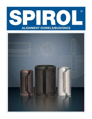
SPIROL roll-formed, hardened Spring Dowels and Dowel Bushings are designed to align mating components, eliminate drilling of a separate bolt hole, protect bolts from shear loading, and/or maintain joint integrity. The 12-page design guide provides product specification data and pages of helpful design guidelines. Four pages of applications are included.

Recommended
More Related Content
What's hot
What's hot (13)
Similar to SPIROL Spring Alignment Dowels and Bushings Catalog
Similar to SPIROL Spring Alignment Dowels and Bushings Catalog (20)
More from SPIROL
More from SPIROL (8)
Recently uploaded
Recently uploaded (20)
SPIROL Spring Alignment Dowels and Bushings Catalog
- 2. 2 SPIROL’s roll formed hardened Bushings are designed to meet one or more of the following objectives: ¥ Align mating components, ¥ Eliminate drilling of a separate bolt hole, ¥ Protect bolts from shear loading, and/or ¥ Maintain joint integrity Although these hollow, lightweight Bushings are not precision ground and do not require precision holes, thus saving in component and hole preparation costs, they are capable of precision alignment if the design guidelines are followed. Further savings can be achieved by using the inside of the Dowel Bushing for the bolt and thus eliminating the cost of a separate bolt hole. This design concept also protects the bolt from shear loads perpendicular to the bolt and isolates the forces on the bolt to tension loading. Shear forces acting on a bolted joint cause the joint members to slip back and forth, which causes the bolts and nuts to rotate, reducing the pre-load tension. This is particularly the case with short bolts with a reduced clamping distance. Spring Alignment Dowels/Bushings
- 3. 1 SPRING ACTION The diameter of the Bushing is slightly largerthanthehole. Thespringactionof the Bushing allows it to be installed into a drilled or cored hole and assume the diameter of the hole. It is self-retained once installed. Product Features and Benefits CONTROLLED INSIDE DIAMETER The inside diameter of the Dowel Bushings is designed to provide clearanceforaboltthroughtheBushing for the purpose of fastening the aligned components together. This isolates the bolt from the shear loading and increases the joint integrity. It also eliminates the cost of a separate hole. STAGGERED SEAM The staggered seam prevents interlocking, making these Bushings suitable for automatic feeding and eliminating the need to separate them during manual assembly. LEAD-IN CHAMFERS The beveled chamfer around the entire periphery of the Bushing is designed to facilitate ease of insertion and to avoid skiving of the Bushing during installation. 1
- 4. 2 Dowel Bushings Dowel Bushings are used to locate components in conjunction with bolts which pass through the inside of the Dowel after it has been installed. Separate holes for locating pins are eliminated. The hardened Dowels also absorb shear loads, isolating the bolts from these forces. Series DB100 Inch Nominal Bolt Diameter Min. ØID Installed1 ØOD Wall Thickness T Chamfer Recommended Ø Hole Size Min. Single Shear (lbs.)2 Min. Max. C Length ØB Max. Min. Max. .250 1/4 .256 .325 .335 .028 .050 .308 .315 .320 2,500 .312 5/16 .318 .401 .411 .035 .050 .381 .391 .396 4,000 .375 3/8 .381 .479 .489 .042 .050 .457 .469 .474 5,750 .500 1/2 .510 .640 .650 .057 .060 .615 .630 .635 10,500 Inch Nominal Bolt Diameter Length .500 .750 1.000 1.250 1/2 3/4 1 1-1/4 .250 1/4 .312 5/16 .375 3/8 .500 1/2 LENGTH TOLERANCE +.000” -.030” Metric Nominal Bolt Diameter Length 12 15 20 25 30 35 6 8 10 12 16 LENGTH TOLERANCE + 0.0mm - 1.0mm MATERIAL FINISH B High Carbon Steel K Plain, Oiled Metric Nominal Bolt Diameter Min. ØID Installed1 ØOD Wall Thickness T Chamfer Recommended Ø Hole Size Min. Single Shear (kN)2 Min. Max. C Length ØB Max. Min. Max. 6 6.20 7.92 8.18 0.70 1.40 7.50 7.67 7.80 10.9 8 8.20 10.35 10.61 0.90 1.40 9.85 10.10 10.23 18.7 10 10.20 12.75 13.01 1.10 1.40 12.20 12.50 12.63 28.4 12 12.25 15.50 15.76 1.45 1.80 14.85 15.25 15.38 45.4 16 16.25 20.25 20.51 1.80 1.80 19.50 20.00 20.13 74.6 DIMENSIONAL DATA 1 When installed in recommended hole. 2 Single shear minimum, tested in accordance with ISO 8749 and ASME B18.8.2 Appendix B. Testing can only be performed on Dowels greater than two diameters in length. • On special order plated parts, all dimensions apply prior to plating. • Special lengths and sizes available upon request. T Ref. C Ref. ØODØB L+0 -LTol To Order: BUSH, Nominal Dowel Size x Length, Material, Finish, Series Example: BUSH 10 x 25 BK DB100
- 5. 3 Spring Dowels Spring Dowels are used to accurately locate components with respect to each other. They are formed around arbors to assure roundness. It is recommended that one half the hole tolerance be used for the fixed location of the Dowel and one half for the hole in the mating part. Series SD200 Metric Nominal Dowel Diameter Length 12 15 20 25 30 6 8 10 12 MATERIAL FINISH B High Carbon Steel K Plain, Oiled Metric Nominal Dowel Diameter ØOD Wall Thickness T Chamfer Recommended Ø Hole Size Min. Single Shear (kN)1 Min. Max. C Length ØB Max. Min. Max. 6 6.25 6.50 0.55 1.00 5.85 6.00 6.13 6.6 8 8.25 8.50 0.70 1.40 7.80 8.00 8.13 11.5 10 10.25 10.50 0.90 1.40 9.75 10.00 10.13 18.5 12 12.25 12.50 1.10 1.40 11.70 12.00 12.13 27.1 DIMENSIONAL DATA 1 Single shear minimum, tested in accordance with ISO 8749. Testing can only be performed on Dowels greater than two diameters in length. • On special order plated parts, all dimensions apply prior to plating. • Special lengths and sizes available upon request. • Inch sizes available upon request. T Ref. C Ref. ØODØB L+0 -1.0 To Order: BUSH, Nominal Dowel Size x Length, Material, Finish, Series Example: BUSH 8 x 20 BK SD200
- 6. 4 Design Guidelines Doweling to Fix Relative Location Of Components The more common application is to use the Dowels to fix the relative location of two or more components. In this situation, the Dowels are partially installed in one component, the initial installation, and then holes in the mating component are pushed over the exposed end of the partially installed Dowel. The following factors need to be considered for precision location: ¥ Hole dimension tolerance ¥ Relative depth of initial installation ¥ Total length of the Dowel ¥ True position of hole centerlines These factors are interrelated and need to be considered together. The following general guidelines are helpful in determining the best design in a specific situation. ¥ Precise holes with reduced hole tolerances increase the cost but also increase location accuracy and simplify the design considerations. ¥ Wider hole tolerances require longer Dowels to assure a tight, non-clearance fit in both components. ¥ Hole tolerance should be minus in the initial installation hole and plus in the mating component hole. ¥ The maximum hole tolerance should not exceed one half (1/2) of the recommended tolerance range to allow for hole tolerancing of both holes within the tolerance range. ¥ Fixing the Dowel location in a through hole can be achieved through length of engagement and hole tolerancing, or both. Generally, an engagement of 60% of the total length in the smaller hole is recommended for the fixed location. ¥ If more than one Dowel is used, holes in the upper recommended tolerance range allow for a wider tolerance in centerline location. Doweling for Permanent Positioning If components are located or positioned by methods other than the Doweling itself, and the issue is to allow for disassembly and then re-assembly with the components in exactly the same location – then it is recommended that the components be drilled together and the Dowel installed in the assembled condition. During disassembly, the Dowel may be removed and reinstalled during re-assembly. This method eliminates the need for hole tolerancing and hole centerline concerns. It provides for very accurate permanent locating.
- 7. 5 Design Guidelines Precise Holes If the holes are precise and the same in both components, such as honed or reamed holes with a tolerance of .0008” or 0.002mm, then the length of the Bushing need only receive minor consideration for purposes of precise relative location. We recommend using the minimum specified hole in these situations. The Bushing will assume the diameter of the initial installation hole and the unsized diameter of the normally exposed end would compensate for the tolerance difference between the holes if any. If no interferencewhatsoeverisacceptablewhenassembling the mating component over the exposed Bushing, then it is recommended to keep the exposed Dowel length to a minimum, or if practical, to push the Dowel through the initial component to size the exposed end. In any event it is recommended to install at least two thirds of the total Dowel length into the initial hole so as to permanently fix the Dowel position. Maximum Tolerance Holes The maximum allowable tolerance is one-half the total recommended tolerance. This is still within the normal productionholetolerancefordrilledorcoredholes. The smaller hole, that is the hole with the minus tolerance, should be the hole into which the Dowel is initially installed. The larger hole, that is the hole in the mating component, should have a plus tolerance. To illustrate: The total recommended hole tolerance for an ø8mm Dowel is ø8.00 to ø8.13mm. Take the approximate midpointandsplitthetolerance. Thesmallerholewould beø8.00toø8.06mm,thelargerø8.06toø8.13mm. The smaller hole used for the initial installation will size the Dowel but the protruding unsized length of the Dowel remains larger, with the diameter increasing as the distance from the hole increases. It normally requires a protruding length equal to 1-1/2 times the Dowel diameterforaDowelinstalledinaminimumholetohave a protruding diameter greater than the maximum hole. Foranø8mmDowelinaø8mmhole,thatwouldrequire a protrusion of 12mm to have a Dowel diameter at the protruding end greater than ø8.13mm. The smaller hole in the initial installation helps in fixing the location of the Dowel but it is still recommended that the greater length of engagement be in the smaller initial hole. Therefore, in the example used here to illustrate the maximum hole tolerance situation, the Dowel would be BUSH 8 x 30 BK SD 200. Total hole tolerance = ø8.00 to ø8.13mm Hole for fixed Dowel location = ø8.00 to ø8.06mm Mating component hole = ø8.06 to ø8.13mm ø8.13mm (Maximum hole diameter of mating component) ø8.00mm (Smallest diameter with tolerance) 12mm 18mm Equal to hole diameter ≤1 outside diameter ≥60% of Dowel length
- 8. 6 Centerline Tolerancing If more than one Dowel is used, centerline tolerancing for hole positioning becomes an issue. In situations with precision holes requiring precision locating, the centerline tolerancing needs to be accurate and similar to tolerancing used for solid Dowels. A tolerance of .0006” or 0.0015mm is recommended. When a Dowel is installed in a minimum hole, which is recommended in these cases, the Dowel gap is butted and further spring action is very limited, if any. Hole tolerance can be increased to provide for relaxed positioning tolerances with some sacrifice of rigidity. The centerline tolerance can be increased to the tolerance of the holes, or the smallest tolerance if the tolerances of the holes are different. In the ø8mm Dowel example used, the centerline tolerance can be 0.06mm. The net hole at maximum misalignment cannot be less than the smallest recommended hole; in the example, ø8mm. The misalignment will normally distribute itself between the Dowels. If it is a Dowel Bushing application with a bolt passing through the Dowel into a threaded component, the clearance between the minimum inside diameter of the Dowel Bushing and maximum bolt diameter needs to be enough to compensate for misalignment. If these guidelines are used, the standard clearance will always be adequate at maximum misalignment. SPIROL APPLICATION SPECIALISTS ARE AVAILABLE TO MAKE RECOMMENDATIONS BASED ON YOUR REQUIREMENT OR TO REVIEW YOUR APPLICATION. Blind Holes and Stepped Holes Blind and stepped holes can be used for Dowel location and stepped holes are generally used for Dowel Bushings used in conjunction with bolts. Since blind and stepped holes only fix the Dowel location in one direction, it is still recommended that the Dowel be fixed into location by using the smaller hole and greater length of engagement. Joint Integrity Loss of joint integrity due to rotational loosening is triggered by vibration. Loads perpendicular to the axis of the bolt, particularly cyclic loading cause slip at the bolt head or the nut which translates into rotational loosening. Dowels, particularly Dowel Bushings, reduce or even eliminate rotational loosening. In this instance, the use of the smallest hole possible within the tolerance range is recommended to reduce Dowel flexibility after insertion. The shear strength also needs review. In static loading or a long cycle time between loads, maximum load should not exceed of 75% of the minimum shear strength. When the loads are in the form of severe vibration, 50% is recommended.
- 9. 7 Applications ENGINE HOUSING ENGINE CAM SHAFT CAPS SWITCH HOUSING ASSEMBLY
- 10. 8 INTAKE MANIFOLD HOUSING OIL PUMP ASSEMBLY VALVE
- 11. 9 OIL PUMP HOUSING TRANSMISSION SOLENOID HOUSING
- 12. SPIROL Application Engineers will review your application needs and work with you to recommend the optimum solution. One way to start the process is to visit our Optimal Application Engineering portal at SPIROL.com. © 2018 SPIROL International Corporation 02/18 SPIROL International Corporation 30 Rock Avenue Danielson, Connecticut 06239 U.S.A. Tel. +1 860 774 8571 Fax. +1 860 774 2048 SPIROL Shim Division 321 Remington Road Stow, Ohio 44224 U.S.A. Tel. +1 330 920 3655 Fax. +1 330 920 3659 SPIROL Canada 3103 St. Etienne Boulevard Windsor, Ontario N8W 5B1 Canada Tel. +1 519 974 3334 Fax. +1 519 974 6550 SPIROL Mexico Avenida Avante #250 Parque Industrial Avante Apodaca Apodaca, N.L. 66607 Mexico Tel. +52 81 8385 4390 Fax. +52 81 8385 4391 SPIROL Brazil Rua Mafalda Barnabé Soliane, 134 Comercial Vitória Martini, Distrito Industrial CEP 13347-610, Indaiatuba, SP, Brazil Tel. +55 19 3936 2701 Fax. +55 19 3936 7121 SPIROL France Cité de l’Automobile ZAC Croix Blandin 18 Rue Léna Bernstein 51100 Reims, France Tel. +33 3 26 36 31 42 Fax. +33 3 26 09 19 76 SPIROL United Kingdom 17 Princewood Road Corby, Northants NN17 4ET United Kingdom Tel. +44 1536 444800 Fax. +44 1536 203415 SPIROL Germany Ottostr. 4 80333 Munich, Germany Tel. +49 89 4 111 905 71 Fax. +49 89 4 111 905 72 SPIROL Spain 08940 Cornellà de Llobregat Barcelona, Spain Tel. +34 93 193 05 32 Fax. +34 93 193 25 43 SPIROL Czech Republic Sokola Tůmy 743/16 Ostrava-Mariánské Hory 70900 Czech Republic Tel/Fax. +420 417 537 979 SPIROL Poland ul. Solec 38 lok. 10 00-394, Warszawa, Poland Tel. +48 71 399 44 55 SPIROL Asia Headquarters 1st Floor, Building 22, Plot D9, District D No. 122 HeDan Road Wai Gao Qiao Free Trade Zone Shanghai, China 200131 Tel. +86 21 5046 1451 Fax. +86 21 5046 1540 SPIROL Korea 160-5 Seokchon-Dong Songpa-gu, Seoul, 138-844, Korea Tel. +86 (0) 21 5046-1451 Fax. +86 (0) 21 5046-1540 Europe Americas Asia Pacific Technical Centers info@spirol.com Please refer to www.SPIROL.com for current specifications and standard product offerings. e-mail: SPIROL.com Installation Technology Coiled Spring Pins Rolled Tubular Components Spacers Parts Feeding Technology Dowel Bushings / Spring Dowels Inserts for Plastics Precision Shims & Thin Metal Stampings Disc Springs Solid Pins Ground Hollow Dowels Slotted Spring Pins Precision Washers Compression Limiters Innovative fastening solutions. Lower assembly costs.