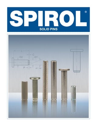
SPIROL Straight Solid Pins, Knurled Solid Pins, and Headed Solid Pins
•
0 likes•226 views

Specifying SPIROL Solid Pins provides the lowest cost and the most responsive delivery. Standards include SPIROL® Straight Pins, Knurled Pins, Headed Pins and Headed Knurled Pins. Standard materials have been selected to meet the requirements of ASME and ISO product standards and to cover a range of requirements as dictated by the market.

Recommended
Recommended
More Related Content
What's hot
What's hot (19)
Similar to SPIROL Straight Solid Pins, Knurled Solid Pins, and Headed Solid Pins
Similar to SPIROL Straight Solid Pins, Knurled Solid Pins, and Headed Solid Pins (20)
Recently uploaded
Recently uploaded (20)
SPIROL Straight Solid Pins, Knurled Solid Pins, and Headed Solid Pins
- 1. 1 SOLID PINS D2 C 25˚ - 40˚ D1 P
- 2. 2 Providing innovative solutions for fastening and joining since 1948! SPIROL stands apart from all other companies in our industry. We are a technical resource that provides high quality components that improve the quality of your assembly, extend the life of your products and reduce your manufacturing costs. SPIROL has Application Engineers throughout the world to assist you in your designs, supported by state-of-the-art manufacturing centers and worldwide stocking facilities to simplify the logistics of delivering your product. Local Design, Global Supply Contact SPIROL for design assistance: www.spirol.com/s/solidpindesign/ N. America S. America Europe Asia/Pacific Apodaca, Nuevo León: Mexico São Paulo: Brazil Corby, Northants: England Barcelona: Spain Stow, Ohio: United States Danielson, Connecticut: United States Windsor, Ontario: Canada Munich: Germany Ostrava: Czech Republic Reims: France Kyoto: Japan Seoul: South Korea Shanghai: China Warszawa: Poland
- 3. 1 With so many types of industrial standard pins to choose from, the challenge for the designer is to select the most cost-effective pin that meets the specific application requirements. While more than one type of pin may meet certain requirements, here are some general guidelines when a Solid Pin may be most suitable: • When a head is required for a positive stop or to retain a thin member to a thicker member of the assembly • When a smooth, uninterrupted surface is required such as when used in conjunction with a pawl or other angular component • When a hollow pin is not suitable such as when the designer is looking to plug a hole (i.e. Restrict passage of liquids) • When there is a need to manually align several clearance holes • When increased bending or shear strength is required • When precise hole locations need to be maintained WHY USE A SOLID PIN? SPIROL maintains a library of application case studies for online review at www.spirol.com. SPIROL has a standard offering of Straight Pins, Knurled Pins and Barbed Pins. The specifications for these pins can be found on pages 4-7. Straight Pins – Offered with or without a head, Straight Pins are distinguished by their uniformity. The chamfered ends are more consistent than tumbled edges—making installation with automatic assembly equipment more reliable. Straight Pins are retained by compressing the host, not the pin. They are suitable for use in plastics for press-fit applications limited to those cases where the host material can withstand compression in the order of .002” – .003” (0.05mm – 0.08mm). These pins are often used to replace ground dowels in applications that do not require the tight tolerances of a ground dowel. Knurled Pins – Offered with or without a head, Knurled Pins are available with either straight or helical knurls. Unlike a Straight Pin where retention is provided by the uniform interference between the pin and hole, knurled pins are designed to cut into the host. The displacement of the host material into the valleys of the knurls yields more frictional contact area between the pin and hole thus resulting in higher retention. With Helical Knurled Pins, a 30° knurl causes the pin to rotate as it enters the hole creating even more surface contact with the host. This results in higher frictional forces, greater engagement and improved resistance to back out. Barbed Pins – Offered with a head, Barbed Pins were created specifically for use in plastic assemblies. The raised barbs are angled backwards, opposite the direction of insertion for maximum retention. All Barbed Pins are provided with a generous pilot to facilitate alignment with the hole and ease installation. SPIROL SOLID PINS CUSTOMIZED PRODUCTS TO MEET YOUR APPLICATION REQUIREMENTS One of the advantages of partnering with SPIROL early in the design stage is that if one of our 30,000 standard items doesn’t meet your specific application requirements, the solution is often a simple derivation of our standard design. Regardless of the complexity, SPIROL’s Engineers will work with you to develop a pin to meet the exact requirements of your application at the lowest total manufacturing cost.
- 4. 2 DESIGN GUIDELINES SPIROL manufactures Solid Pins with straight knurls, helical knurls and barbs. There are many overlaps as to the applications in which these retention features can be used successfully. Straight knurls have lower insertion forces than helical knurls, offer resistance to turning within the assembly, but provide limited retention when axially loaded. Therefore, straight knurls are often recommended when the pin is used to transmit torque such as when used as an axle to rotate a wheel. Helical knurls provide both resistance to torque and push out when axially loaded. Barbs are recommended for use in flexible plastics where optimum resistance to axial force is desired. After installation, the plastic will backfill into the area around the barbs resulting in maximum retention. Barbs are not appropriate for brittle plastics or those containing high percentages of fillers. As barbs are a radial feature, they do not resist rotation of two components relative to one another. For this requirement, a straight or helical knurl should be used. KNURL/BARB LOCATION It is sometimes necessary for the purpose of assembly, retention or function to modify the knurl length or location on the pin. The location of the retention feature can be customized to suit design requirements. More specifically, rather than having the knurls or barbs spanning the full length of the pin, a partial-length knurl or barb, or set of partial-length knurls (or barbs) can be located anywhere along the tenon of the Solid Pin to coincide with the component in which it will be retained. An example of this is given on the right. The designer of a plastic handle wanted to have the pin securely held in one component and have the other component rotate freely around the pin when the plastic handle was actuated. SPIROL designed a Solid Pin with a barb located under the head with a barb length equal to the width of the outermost section of the assembly. The remaining length of the pin was smooth and had no retention feature. This allowed the pin to easily align and freely install through all of the holes of the assembly until the barb made contact with the final hole to securely lock the pin in place. Once fully installed, the handle would pivot freely around the non-barbed end of the stationary pin. The head prevented the pin from being over-installed, and enabled the pin to be mechanically oriented for automatic installation. HOW TO SELECT THE PROPER RETENTION FEATURE HOLE DESIGN When the Solid Pin is retained by being press-fit into the assembly, it is important for the pin to be harder than the host material. Otherwise, the pin will be deformed during installation. If a higher hardness is required, Solid Pins can be produced from alloy steel and through-hardened. SPIROL’s Application Engineers will review your requirements and work with your design team to recommend the best solution at the lowest total assembly cost. It is important to note that the recommended hole sizes (on pages 4-7) are guidelines based on typical applications and may require modification depending on the hardness of the materials or required engagement. Additionally, there are many applications that require a different hole size to ensure the proper function of the assembly. For this reason, it is recommended that SPIROL be consulted on new designs.
- 5. 3 SPECIAL MATERIALS SPIROL has extensive experience with special materials required for unique circumstances such as: MATERIALS AND FINISHES Austenitic (Nickel) Stainless Steel (D) Austenitic stainless steel provides excellent corrosion protection against normal environmental conditions. It withstands fresh water and atmospheric marine conditions very well, and is suitable for many other industrial conditions including acidic environments. All austenitic stainless Solid Pins are passivated. Low Carbon Steel (F) Low carbon steel is one of the most versatile materials available. This material is readily available, and is the most economical of the standard Solid Pin materials in the absence of any plating or coating. Low carbon Solid Pins have a dry to the touch rust preventative.Additional coatings and finishes can be applied to carbon steel to improve corrosion resistance, however for some applications, it may be more appropriate and cost beneficial to specify stainless steel when a high level of corrosion resistance is required. Plain/Oiled (K) This finish is a thin coating of dry-to-the touch oil that provides corrosion resistance during storage and shipping. Since this lubricating oil is suspended in a carrier which evaporates over time, the pins are dry-to-the-touch and conducive for automatic feeding and assembly. Passivated (P) Passivation of stainless steel Solid Pins is a process whereby surface contaminates such as embedded tool steel and other free iron particles are removed. The sole purpose of passivation is to remove embedded iron; not to clean the part. While all stainless steel Solid Pins are passivated as a standard, there are some critical applications that absolutely require passivation such as medical devices, components used in the food or drug industry, fuel system applications, and any application requiring a clean environment. Available only for stainless steel. STANDARD MATERIALS STANDARD FINISHES TYPE F - Low Carbon Steel D - Stainless Steel,Austenitic (Nickel) FINISHES GRADE UNS G10220 / C20C (1.0411) UNS S30500 / X4CrNi18-12 MATERIALS K - Plain, oiled P - Passivated Alloy Steel (W) Alloy steel is used for applications requiring higher shear strength than our standard materials provide, or when additional hardness is required to ensure that the pin is harder than the host material into which the pin is being installed. Aluminum (A) Aluminum is lightweight, lead free, and has sufficient strength for most plastic applications. Aluminum is less than half the weight of steel, and does not require any supplemental coatings or platings to provide the necessary corrosion protection in most environments. Other materials and finishes are available to order depending on the application requirements (see page 8).
- 6. 4 STRAIGHT PINS Part Number Code TO ORDER: SLDP (Nominal Diameter)x(Length)(Material)(Finish)(Pin Series Number) EXAMPLE: SLDP .156 x 1.250 FK DP100 Notes: • Please consult SPIROL Engineering for recommended hole sizes when used as a press-fit. • Other diameters and lengths available on request. Straight Pin Series DP100 L C D TYP 25°- 40°TYP INCH SPECIFICATIONS 3 2.95 3.00 0.2 4 3.95 4.00 0.3 5 4.95 5.00 0.4 6 5.95 6.00 0.4 2.5 2.45 2.50 0.2 Min. Max. Min. .250 .312 .375 .437 .500 .562 .625 .750 .875 1.000 1.250 1.500 1.750 2.000 Nominal Diameter Diameter “D” Chamfer “C” Length “L” 1/8 .125 .1230 .1250 .008 3/16 .187 .1855 .1875 .015 1/4 .250 .2480 .2500 .015 2 1.95 2.00 0.15 5/32 .156 .1542 .1562 .010 3/32 .094 .0917 .0937 .008 5/64 .078 .0761 .0781 .005 METRIC SPECIFICATIONS Min. Max. Min. 6 8 10 12 14 16 20 24 26 30 35 40 45 50 Length Tolerance ± .010 Length Tolerance ± 0.25 ➤ DIMENSIONAL DATA
- 7. 5 KNURLED PINS Part Number Code TO ORDER: SLDP (Nominal Diameter)x(Length)(Material)(Finish)(Pin Series Number) EXAMPLE: SLDP 3 x 20 FK KP300 * Denotes sizes only available in KP300. Notes: • Recommended hole sizes are given for average conditions. Actual required hole size is dependent on length of knurl engagement and hardness of host material. • Other diameters, lengths and alternative knurl locations available on request. Straight Knurl Series KP200 Helical Knurl Series KP300 25°- 40°TYP L C D TYP L C D TYP 25°- 40°TYP INCH SPECIFICATIONS 3 3.25 3.35 0.2 3.00 3.06 4 4.25 4.35 0.3 4.00 4.08 5 5.25 5.35 0.4 5.00 5.08 6 6.25 6.35 0.4 6.00 6.08 2.5 2.70 2.80 0.2 2.50 2.56 Min. Max. Ref. Min. Max. .250 .312 .375 .437 .500 .562 .625 .750 .875 1.000 1.250 1.500 Nominal Diameter Diameter “D” Chamfer “C” Recommended Hole Length “L” 1/8 .125 .131 .136 .008 .125 .127 3/16 .187 .195 .200 .015 .188 .191 1/4 .250 .256 .262 .015 .250 .253 5/32 .156 .163 .168 .010 .156 .159 3/32 .094 .099 .103 .008 .094 .096 METRIC SPECIFICATIONS Min. Max. Ref. Min. Max. 6 8 10 12 14 16 20 24 26 30 35 40 Length Tolerance ± .010 Length Tolerance ± 0.25 5/64 .078 .084 .088 .005 .078 .080 * * * * * * * 2 2.20 2.30 0.15 2.00 2.06 * * * * * * ➤ DIMENSIONAL DATA
- 8. 6 Notes: • Please consult SPIROL Engineering for recommended hole sizes when used as a press-fit. • Other diameters and lengths available on request. • Series FH100 is available to order with a round head. Part Number Code TO ORDER: SLDP (Nominal Diameter)x(Length)(Material)(Finish)(Pin Series Number) EXAMPLE: SLDP 4 x 16 FK FH100 HEADED PINS Headed Pin Series FH100 C D L 25°- 40° INCH SPECIFICATIONS 3 2.95 3.00 4.95 5.45 0.90 1.20 0.2 4 3.95 4.00 6.75 7.25 1.20 1.50 0.3 5 4.95 5.00 8.50 9.10 1.50 1.80 0.4 6 5.95 6.00 10.20 10.80 1.90 2.20 0.4 2.5 2.45 2.50 4.20 4.60 0.70 0.90 0.2 Min. Max. Min. Max. Min. Max. Min. .250 .312 .375 .437 .500 .562 .625 .750 .875 1.000 1.250 1.500 1.750 2.000 Nominal Diameter Diameter “D” Head Diameter Head Thickness Chamfer “C” Length “L” 1/8 .125 .1230 .1250 .209 .229 .036 .048 .008 3/16 .187 .1855 .1875 .312 .338 .060 .073 .015 1/4 .250 .2480 .2500 .425 .451 .077 .090 .015 5/32 .156 .1542 .1562 .263 .283 .048 .060 .010 3/32 .094 .0917 .0937 .156 .172 .028 .036 .008 METRIC SPECIFICATIONS Min. Max. Min. Max. Min. Max. Min. 6 8 10 12 14 16 20 24 26 30 35 40 45 50 Length Tolerance ± .010 Length Tolerance ± 0.25 5/64 .078 .0761 .0781 .132 .142 .022 .030 .005 2 1.95 2.00 3.30 3.70 0.55 0.75 0.15 ➤ DIMENSIONAL DATA
- 9. 7 P C 25°- 40° L D2 D1 P C 25°- 40° L D2 D1 P L C 25°- 40° D1 D3 HEADED KNURLED PINS Part Number Code TO ORDER: SLDP (Nominal Diameter)x(Length)(Material)(Finish)(Pin Series Number) EXAMPLE: SLDP .250 x .625 FK FH300 * Denotes sizes only available in FH300 and FH400. Notes: • Recommended hole sizes are given for average conditions. Actual required hole size is dependent on length engagement and hardness of host material. • Other diameters, lengths and alternative knurl locations available on request. • Series FH200, FH300 and FH400 are available to order with round heads. Straight Knurl Series FH200 Barbed Series FH400 Helical Knurl Series FH300 4 3.95 4.00 4.25 4.35 4.36 4.46 6.75 7.25 1.20 1.50 0.3 1.2 4.00 4.08 5 4.95 5.00 5.25 5.35 5.36 5.46 8.50 9.10 1.50 1.80 0.4 1.5 5.00 5.08 6 5.95 6.00 6.25 6.35 6.36 6.46 10.20 10.80 1.90 2.20 0.4 2 6.00 6.08 3/16 .187 .1855 .1875 195 .200 .201 .206 .312 .338 .060 .073 .015 .062 .188 .191 Min. Max. Min. Max. Min. Max. Min. Max. Min. Max. Ref. Ref. Min. Max. .250 .312 .375 .500 .625 .750 1.000 Min. Max. Min. Max. Min. Max. Min. Max. Min. Max. Ref. Ref. Min. Max. 6 8 10 12 16 20 24 1/8 .125 .1230 .1250 .131 .136 .139 .144 .209 .229 .036 .048 .008 .039 .125 .127 5/32 .156 .1542 .1562 .163 .168 .170 .175 .263 .283 .048 .060 .010 .046 .156 .159 1/4 .250 .2480 .2500 .256 .262 .264 .269 .425 .451 .077 .090 .015 .078 .250 .253 2.5 2.45 2.50 2.70 2.80 2.86 2.96 4.20 4.60 0.70 0.90 0.2 0.8 2.50 2.56 3 2.95 3.00 3.25 3.35 3.36 3.46 4.95 5.45 0.90 1.20 0.2 1 3.00 3.06 Nominal Diameter Pilot Diameter “D1” Diameter “D2” Diameter “D3” Head Diameter Head Thickness Chamfer “C” Pilot Length “P” Recommended Hole Length “L” INCH SPECIFICATIONS METRIC SPECIFICATIONS 5/64 .078 .0761 .0781 .084 .088 .092 .097 .132 .142 .022 .030 .005 .026 .078 .080 * * * 3/32 .094 .0917 .0937 .099 .103 .107 .112 .156 .172 .028 .036 .008 .031 .094 .096 2 1.95 2.00 2.20 2.30 2.36 2.46 3.30 3.70 0.55 0.75 0.15 0.6 2.00 2.06 * * * ➤ Length Tolerance ± .010 Length Tolerance ± 0.25 DIMENSIONAL DATA
- 10. 8 When reviewing your application, SPIROL’s Application Engineers will first attempt to use a standard product to meet your technical requirements as this offers the most affordable solution and will reduce your total manufacturing cost. During our engineering review, if a standard product cannot meet your application or assembly requirements, our Engineers will design a special product to meet your needs. Many specials are derivations of our standard products and can be produced with minimal investment in development. Others are completely unique and may require a larger investment in development or special processing on our CNC machinery. SPECIAL SIZES SPIROL can manufacture special configured Solid Pins and large diameter special Solid Pins in low volumes up to Ø.750” (Ø19mm) in diameter and 3” (75mm) in length. SPECIAL SURFACE CONFIGURATIONS SPIROL can machine Solid Pins with multiple diameters, grooves, knurls, threads, elongated chamfers, heads, center holes, side holes, as well as those that are turned, shaved, burnished, broached, back drilled, and counterbored. The location and length of the knurls and barbs can be positioned anywhere along the body of the pin to accommodate application-specific requirements. SPECIAL MATERIALS In addition to the standard materials described on page 3, SPIROL’s production technology enables us to produce Solid Pins out of a variety of materials. The most common alternate materials are: • Alloy Steel • Aluminum • Brass • Martensitic Stainless Steel SPECIAL FINISHES SPIROL Engineers have extensive experience in recommending the right combination of materials and finishes to meet application-specific requirements. All special SPIROL Solid Pins are made to order. SPECIALS
- 11. Pin Installation Technology While SPIROL Solid Pins can be installed with a hammer or with an arbor press, we recognize that an essential factor in reducing the overall cost is trouble-free assembly. Installation equipment increases production efficiency, particularly with awkward or small components. Model CR Model SG Model PMH Model PR SPIROL guarantees that our equipment will enhance your productivity and reduce your total manufacturing costs by offering the only performance warranty in the industry. Model HC SPIROL is the only manufacturer of Solid Pins that designs, builds and supports a comprehensive standard line of Pin Installation Equipment ranging from manual to fully automatic modules. We are experts in adapting our standard modules to customer specific applications, including fixturing and holding components for both a quality installation and ease-of- assembly. Our time-tested, proven and reliable equipment can be equipped with options such as rotary index tables, pin sensing, force monitoring, and drilling and pinning combinations for enhanced productivity, heightened process control and error proofing.
- 12. SPIROL Application Engineers will review your application needs and work with you to recommend the optimum solution. One way to start the process is to visit our Optimal Application Engineering portal at SPIROL.com. © 2019 SPIROL International Corporation 02/19 SPIROL International Corporation 30 Rock Avenue Danielson, Connecticut 06239 U.S.A. Tel. +1 860 774 8571 Fax. +1 860 774 2048 SPIROL Shim Division 321 Remington Road Stow, Ohio 44224 U.S.A. Tel. +1 330 920 3655 Fax. +1 330 920 3659 SPIROL Canada 3103 St. Etienne Boulevard Windsor, Ontario N8W 5B1 Canada Tel. +1 519 974 3334 Fax. +1 519 974 6550 SPIROL Mexico Avenida Avante #250 Parque Industrial Avante Apodaca Apodaca, N.L. 66607 Mexico Tel. +52 81 8385 4390 Fax. +52 81 8385 4391 SPIROL Brazil Rua Mafalda Barnabé Soliane, 134 Comercial Vitória Martini, Distrito Industrial CEP 13347-610, Indaiatuba, SP, Brazil Tel. +55 19 3936 2701 Fax. +55 19 3936 7121 SPIROL France Cité de l’Automobile ZAC Croix Blandin 18 Rue Léna Bernstein 51100 Reims, France Tel. +33 3 26 36 31 42 Fax. +33 3 26 09 19 76 SPIROL United Kingdom 17 Princewood Road Corby, Northants NN17 4ET United Kingdom Tel. +44 1536 444800 Fax. +44 1536 203415 SPIROL Germany Ottostr. 4 80333 Munich, Germany Tel. +49 89 4 111 905 71 Fax. +49 89 4 111 905 72 SPIROL Spain 08940 Cornellà de Llobregat Barcelona, Spain Tel. +34 93 669 31 78 Fax. +34 93 193 25 43 SPIROL Czech Republic Sokola Tůmy 743/16 Ostrava-Mariánské Hory 70900 Czech Republic Tel/Fax. +420 417 537 979 SPIROL Poland ul. Solec 38 lok. 10 00-394, Warszawa, Poland Tel. +48 510 039 345 SPIROL Asia Headquarters 1st Floor, Building 22, Plot D9, District D No. 122 HeDan Road Wai Gao Qiao Free Trade Zone Shanghai, China 200131 Tel. +86 21 5046 1451 Fax. +86 21 5046 1540 SPIROL Korea 160-5 Seokchon-Dong Songpa-gu, Seoul, 138-844, Korea Tel. +86 (0) 21 5046-1451 Fax. +86 (0) 21 5046-1540 Europe Americas Asia Pacific Technical Centers info@spirol.com Please refer to www.SPIROL.com for current specifications and standard product offerings. e-mail: SPIROL.com Installation Technology Coiled Spring Pins Rolled Tubular Components Spacers Parts Feeding Technology Dowel Bushings / Spring Dowels Inserts for Plastics Precision Shims & Thin Metal Stampings Disc Springs Solid Pins Ground Hollow Dowels Slotted Spring Pins Precision Washers Compression Limiters Innovative fastening solutions. Lower assembly costs.