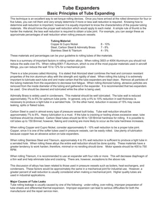
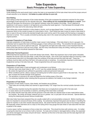
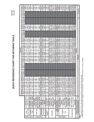
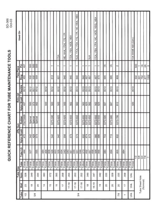
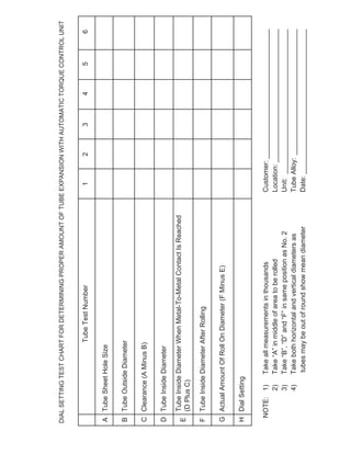
SlideShare a Scribd company logo
1 of 8
Download to read offline
Basic Principles of Tube Expanding
Tube Expanding is the art of reducing a tube wall by compressing the O.D. of the tube against a fixed container . . .
such as rolling tubes into tube sheets, drums, ferrules or flanges. To assure a proper tube joint, the tube wall must
be reduced by a predetermined percentage. The following chart can be used for determining the correct tube wall
reduction.
This chart shows a typical 3/4” – 16 gauge tube. Before rolling this tube you would find the proper rolling dimension
as shown.
A. First determine the tube hole size.
B. Then determine the tube outside diameter.
C. Subtract the tube outside diameter from the tube
hole dimension.
D. With an Elliott Tube Gauge, determine the inside
diameter of the tube before rolling.
E. By adding the dimension found in “D” to the
clearance between the tube O.D. and the tube hole,
you will then know the tube’s inside diameter at
metal to metal contact.
F. Roll the tube to what you feel is a good tube joint.
This example was rolled and then the I.D. of the
tube was checked with an Elliott Tube Gauge.
G. By subtracting “E” from the rolled diameter you
determine the actual amount of expansion (tube
wall reduction) on the inside diameter of your tube.
This can be converted to a % of wall reduction by
dividing the actual wall thickness (“B minus D”)
.130” into the amount of roll .009.
You can use this chart to your advantage by predetermining both the % of wall reduction required and the actual
inside diameter which should be rolled. After the completion of “E” you realize any additional increase of the inside
diameter of the tube will result in actual wall reduction. Since the amount of wall reduction greatly determines the
quality of the tube joint, you should arrive at the % required for your application prior to tube rolling.
By subtracting the tube inside diameter “D” from “B”, you determine actual wall thickness. This example would
therefore be .130”. If you then take the 7% wall reduction times the wall thickness, you arrive at .0091”. Adding
.0091” (“G”) to .627” (“E”) we get “F” the inside diameter of the tube after rolling (.636”).
Tube Test Number 1 2 3 4 5 6
A Tube Sheet Hole Size .757
B Tube Outside Diameter .750
C Clearance (A Minus B) .007
D Tube Inside Diameter .620
E Tube Inside Diameter When Metal-To-Metal .627
Contact is Reached (D Plus C)
F Tube Inside Diameter After Rolling .636
G Actual Amount of Roll on Diameter (F Minus E) .009
Note: 1) Take all measurements in thousands Customer: _______________
2) Take “A” in middle of area to be rolled Location: _______________
3) Take “B”, “D” and “F” in same position as No. 2 Unit: _______________
4) Take both horizontal and vertical diameters as Tube Alloy: _______________
tubes may be out of round show mean diameter Date: _______________
Test Chart For Determining Proper Amount Of Tube Expansion
TM-6 02-10-04
Here is a summary of important factors in rolling certain alloys: When rolling 3003 or 4004 Aluminum you should not
reduce the walls over 5%. When rolling 6061-T Aluminum, which is one of the most popular materials used in aircraft
fittings, you can reduce the wall 10 to 12% for a mechanical joint.
There is a tube process called Alonizing. It is stated that Alonized steel combines the heat and corrosion resistant
properties of the iron aluminum alloy with the strength and rigidity of steel. When rolling this tubing it is extremely
important to lubricate each tube end and make certain that the tube expanders are kept clean. Remove all particles of
the tubing materials from the expanders to decrease tool fatigue. When rolling Alonized tubing, abrasive particles are
removed from the inside diameter of the tubing and gathered in the expander. It is recommended that two expanders
be used. One should be cleaned and lubricated while the other is being used.
Admiralty Brass is widely used in condensers. This material should be well lubricated. The tube wall is reduced
approximately 7% to 8% for optimum tube joints. In general, only a 4% to 10% reduction in wall thickness is
necessary to produce a tight tube in a serrated hole. On the other hand, reduction in excess of 15% may cause
leaking, splits or flaked tubes.
Carbon Steel is used in almost every type of pressure vessel built today. Tube wall reduction should be
approximately 7% to 8%. Heavy lubrication is a must. If the tube is cracking or tooling shows excessive wear, tube
hardness should be checked. Carbon Steel tubes should be 90 to 120 Brinnel hardness for rolling. It is possible to
roll tubes up to 150 Brinnel; however, flaking and cracking are more likely to occur as the tube hardness increases.
When rolling Copper and Cupro Nickel, consider approximately 8 - 10% wall reduction to be a proper tube joint.
Copper, since it is one of the softer tubes used in pressure vessels, can be easily rolled. Use plenty of lubrication
because copper has an abrasive action on tube expanders.
When rolling Stainless Steel and Titanium, approximately 4 to 5% wall reduction is sufficient to produce a tight tube in
a serrated hole. When rolling these alloys the entire wall reduction should be done quickly. These materials have a
greater tendency to work harden; therefore, minimal or no rerolling should done. Motor speeds should be 400 to 750
RPM.
When rolling Titanium, it is recommended to use an expander with four rolls or more. This will decrease diaphragm of
a thin wall and help eliminate tube end cracking. There are, however, exceptions to the above rule.
This discussion of alloys has been related to those used in pressure vessels such as boilers, heat exchangers, and
condensers. These factors would be approximately the same in a mechanical joint for industrial use. However, a
greater percent of wall reduction is usually considered when making a mechanical joint. Higher quality tubes are
used in industrial applications.
Major Causes of Tube Leaks
Tube rolling leakage is usually caused by one of the following: under-rolling, over-rolling, improper preparation of
tube sheets and differential thermal expansion. Improper expansion can lead to serious difficulties for both the
manufacturer and the repair service men.
Tube Expanders
Basic Principles of Tube Expanding
This technique is an excellent way to set torque rolling devices. Once you have arrived at the rolled dimension for four or
five tubes, you can roll them and very simply determine if more or less wall reduction is required. Knowing how to
determine wall reduction is important; however it is equally important to know the characteristics of the popular tubing
materials. We should know the proper wall reduction which would apply to each metal. A simple rule of thumb is the
harder the material, the less wall reduction is required to obtain a tube joint. For example, you can assign these as
approximate percentages of wall reduction when rolling pressure vessels:
Tubing Material:
Copper & Cupro Nickel 8 - 10%
Steel, Carbon Steel & Admiralty Brass 7 - 8%
Stainless Steel & Titanium 4 - 5%
These materials and percentages can be your guideline to rolling tubes of like materials.
Over-rolling also causes distortion in tube sheets or drums, such as egg-shaped holes. It will also cause diametrical
expansion which is the overall increase of a tube sheet or drum. Over-rolling has been known to cause a tube sheet to
bow or warp to the point where the standard length tube could not be used in the vessel until the bowing or warpage is
returned to normal. This is usually corrected by placing stay rods in the vessel and pulling the tube sheets back to their
original position.
Improper Preparation of Tube Holes
Improper preparation of tube holes is another major cause in tube leakage. If the tube sheet or drum is gouged, it is
extremely hard to expand the tube to fill these gouges or tears without over-rolling. The smoother the tube seat or tube
hole the easier it is to roll an optimum tube joint. The ligaments and light tube walls make it more important that the
finish of the tube hole be in the low micro range. We find many manufacturers today are drilling, reaming and sizing or
burnishing to get the microfinish desired for tube holes.
Differential Thermal Expansion
Differential thermal expansion can result with thicker tube sheets. When the expansion due to heat varies noticeably
between the thinner tube and tube sheet, a shift of the tube results. One of the most important steps for ensuring a safe
and permanent tube joint is to thoroughly clean the surfaces of the tube end and the tube hole wall. These two
surfaces must be clean and free of all dust, mill scale and pits or scratches. It is extremely important to eliminate any
longitudinal scoring in the tube hole wall. These longitudinal lines will cause leaky tubes.
Preparation of Tube Holes
Preparation of tube holes in heat exchangers and condensers is as follows:
1. Drill and ream tube sheet holes to .007” to .010” over the outside diameter of the tube to be used.
2. Be certain the ligaments are sufficient to guarantee a safe and permanent tube joint.
3. When conditions permit, utilize a sizing or burnishing tool to further assure a good finish in the tube hole. This will
also increase the tensile strength of the ligament.
4. The serrations or grooves to be used will determine the holding power of the tube.
5. It is extremely important when retubing that the grooves be cleared of all metals or any foreign material.
Preparation of Tube Seats
Preparation of tube seats in drums, tube sheets, and headers are as follows:
1. Tube holes are normally drilled and reamed to approximately 1/32” larger than the nominal outside diameter of the
tubes.
2. It is extremely important during this operation that there are no longitudinal scorings left in the tube seat.
3. In cases where out-of-roundness is extreme, prerolling of the tube holes is advised.
4. Be certain that the tube hole walls and the grooves in the tube walls are cleaned down to bare metal before tubes
are inserted. Be certain all foreign material such as oil, grease, rust, or just plain dirt are removed. Special attention
during this cleaning will prevent serious trouble later.
After tube holes have been prepared they are usually coated with a rust preventative compound. Before inserting any
tube it is important to remove all traces of this coating. It is extremely important that great care be taken in handling the
tubes for insertion in all of the vessels discussed above. Be certain that the tube ends are clear of any foreign material.
Be especially certain that there are no chips on the tubing which may gouge the tube sheet or tube seat when the tube
is placed in the vessel.
In some cases it will be necessary to force a tube into a tube hole. This should be done with extreme care. It is better
to spring the tube than to try to force it with a hammer. If a tube end is kinked or damaged before rolling, the expanded
end will be damaged and a leaky roll joint will result. Attention at this time to the tube ends and the tube alignment will
prevent future troubles.
Tube Expanders
Basic Principles of Tube Expanding
Under-Rolling
Under-Rolling as the word would imply is when the tube is not expanded to fill the tube sheet hole and the proper amount
of wall reduction is not obtained. It is better to under-roll than to over-roll.
Over-Rolling
Over-rolling is when the expansion of the inside diameter of the tube surpasses the expansion required for the proper
percentage of wall reduction for the ultimate tube joint. Over-rolling can do considerable damage to a vessel. Over-
rolling will decrease the dimensions of the ligament between tubes and weaken this bridge. Once a ligament is
weakened, it will cause a reaction in all ligaments surrounding that weak ligament. If we decrease the strength of the
ligament the tube next to the tube being rolled will leak.
RECOMMENDED EXPANSION OF TUBES FOR OPTIMUM JOINT STRENGTH
IN HEAT EXCHANGERS AND CONDENSERS
3/4” 10 .008”
3/4” 11 .008”
3/4” 12 .008”
3/4” 13 .008”
3/4” 14 .008”
3/4” 15 .007”
3/4” 16 .006”
3/4” 17 .005”
3/4” 18 .005”
3/4” 19 .005”
3/4” 20 .005”
3/4” 21 .004”
1” 8 .009”
1” 9 .009”
1” 10 .009”
1” 11 .009”
1” 12 .009”
1” 13 .008”
1” 14 .008”
1” 15 .007”
1” 16 .006”
1” 17 .005”
1” 18 .005”
1/2” 14 .006”
1/2” 15 .006”
1/2” 16 .006”
1/2” 17 .005”
1/2” 18 .005”
1/2” 19 .004”
1/2” 20 .004”
1/2” 21 .004”
5/8” 12 .006”
5/8” 13 .006”
5/8” 14 .006”
5/8” 15 .006”
5/8” 16 .006”
5/8” 17 .005”
5/8” 18 .005”
5/8” 19 .004”
5/8” 20 .004”
5/8” 21 .004”
1-1/4” 8 .010”
1-1/4” 10 .010”
1-1/4” 12 .009”
1-1/4” 14 .008”
1-1/4” 16 .007”
1-1/4” 18 .006”
1-1/2” 8 .012”
1-1/2” 10 .012”
1-1/2” 12 .010”
1-1/2” 14 .010”
1-1/2” 16 .008”
1-1/2” 18 .008”
2” 8 .012”
2” 10 .012”
2” 12 .011”
2” 14 .010”
2” 16 .008”
2” 18 .008”
O.D. Tube
Size GA Expansion
Use expansion listed in tube expansion column plus clearance between tube O.D. and sheet hole I.D.
Recommended expansion may be plus or minus .001”.
ADDITIONAL SIZES
1/4” O.D. tube - expand all gauges .003” after contact with tube sheet hole
3/8” O.D. tube - expand all gauges .004” after contact with tube sheet hole
EXAMPLE
3/4” O.D. x 14 gauge tubes
Recommended expansion.............................................. .008”
Tube sheet hole ............................................................. .760”
Therefore, expand as follows:
Tube I.D. before expanding ............................................ .584”
Recommended expansion.............................................. .008”
Clearance between tube & tube sheet hole .................... .010”
FINISH I.D. .602”
The above recommendation is based on our experience. However, this does not constitute a
guarantee because of the great variety of materials, tubes and tube sheets used. Some conditions
will require experimental rolling to be certain that the rolled joints will be satisfactory.
O.D. Tube
Size GA Expansion
O.D. Tube
Size GA Expansion
QUICKREFERENCECHARTFORRETUBINGTOOLS
SD-367
Oct-03
QUICKREFERENCECHARTFORTUBEMAINTENANCETOOLS
SD-366
Oct-03
DIALSETTINGTESTCHARTFORDETERMININGPROPERAMOUNTOFTUBEEXPANSIONWITHAUTOMATICTORQUECONTROLUNIT
TubeTestNumber123456
ATubeSheetHoleSize
BTubeOutsideDiameter
CClearance(AMinusB)
DTubeInsideDiameter
E
FTubeInsideDiameterAfterRolling
GActualAmountOfRollOnDiameter(FMinusE)
HDialSetting
NOTE:1)TakeallmeasurementsinthousandsCustomer:__________________________________
2)Take“A”inmiddleofareatoberolledLocation:___________________________________
3)Take“B”,“D”and“F”insamepositionasNo.2Unit:______________________________________
4)TakebothhorizontalandverticaldiametersasTubeAlloy:_________________________________
tubesmaybeoutofroundshowmeandiameterDate:______________________________________
TubeInsideDiameterWhenMetal-To-MetalContactIsReached
(DPlusC)
tube
expanders
Boiler Expanders
Heat Exchanger Expanders
Condenser Expanders
Refinery Expanders
tube rolling motors
& torque controls
Electric
Pneumatic
tube
cleaners
Air & Water Driven Motors
(Internal/External Drives)
Jiffy Guns
(“Shoot-Thru” Devices)
Roto-Jet
(Rotating Flex Shaft)
additional
products
Tube and Joint Testers
Tube Plugs
(High & Low Pressure)
retubing
tools
Tube Gauges
Tube Cutters
Manual Tools
Spear Type Tube Pullers
Collet-Type Tube Pullers
CYCLGRIP Tube Extractors
Grooving Tools
End-Prep Tools
metal working
products
Back Chamfering Tools
Carbide Roller Burnishing Tools
Diamond Burnishing Tools
Elliptical Deburring Tools
Fine Boring Tools
Internal Recessing Tools
Magic Vise
Mechanical Joining Tools
Roller Burnishing Tools
Single Blade Reamers
Elliott offers a complete line of precision tube tools, including:
Elliott Tool Technologies Ltd • 1760 Tuttle Avenue • Dayton, Ohio 45403 U.S.A.
Phone: +1 800 332 0447 • +1 937 253 6133 • Fax: +1 937 253 9189
Elliott Tool Technologies UK Ltd • Broadstone Hill • Old Chalford • Chipping Norton • OXON • OX7 5QL • England
Phone: +44 (0) 1608 672815 • Fax: +44 (0) 1608 672810
www.elliott-tool.com
TM-6
02-10-04

More Related Content

What's hot

MEASURING, CUTTING, AND JOINING PIPES
MEASURING, CUTTING, AND JOINING PIPESMEASURING, CUTTING, AND JOINING PIPES
MEASURING, CUTTING, AND JOINING PIPESCrislyn Monterde
 
Pipe and joints by jawad ali
Pipe and joints by jawad aliPipe and joints by jawad ali
Pipe and joints by jawad aliJAWAD Ali
 
Basic piping for freshers Engineer
Basic piping for freshers EngineerBasic piping for freshers Engineer
Basic piping for freshers EngineerVaibhav Paydelwar
 
Mud loss or lost circulation
Mud loss or lost circulationMud loss or lost circulation
Mud loss or lost circulationSYED NAWAZ
 
Plumbing fittings & fixtures
Plumbing fittings & fixturesPlumbing fittings & fixtures
Plumbing fittings & fixturesJonathanCaporas
 
Aircraft fluid lines and fittings - Flexible hose
Aircraft fluid lines and fittings - Flexible hoseAircraft fluid lines and fittings - Flexible hose
Aircraft fluid lines and fittings - Flexible hoseAli Borromeo Ismaeili
 
Types of plumbing and pipe fittings
Types of plumbing and pipe fittingsTypes of plumbing and pipe fittings
Types of plumbing and pipe fittingsMani Das
 
PIPES , PIPE FITTINGS,PIPE JOINTS & LAYING OF PIPELINES
PIPES , PIPE FITTINGS,PIPE JOINTS & LAYING OF PIPELINESPIPES , PIPE FITTINGS,PIPE JOINTS & LAYING OF PIPELINES
PIPES , PIPE FITTINGS,PIPE JOINTS & LAYING OF PIPELINESMehul Gohil
 
PPRC piping presentation
PPRC piping presentationPPRC piping presentation
PPRC piping presentationVinayak Abhale
 
Fitting and fixtures
Fitting and fixturesFitting and fixtures
Fitting and fixturesNikhar Mehra
 
Aircraft fluid lines and fittings - Rigid tubing
Aircraft fluid lines and fittings - Rigid tubingAircraft fluid lines and fittings - Rigid tubing
Aircraft fluid lines and fittings - Rigid tubingAli Borromeo Ismaeili
 
Sewer pipes-and-fittings
Sewer pipes-and-fittingsSewer pipes-and-fittings
Sewer pipes-and-fittingsthanhuce
 
Various types of pressure pipes
Various types of pressure pipes Various types of pressure pipes
Various types of pressure pipes Lavanya Singh
 

What's hot (20)

MEASURING, CUTTING, AND JOINING PIPES
MEASURING, CUTTING, AND JOINING PIPESMEASURING, CUTTING, AND JOINING PIPES
MEASURING, CUTTING, AND JOINING PIPES
 
Pipe and joints by jawad ali
Pipe and joints by jawad aliPipe and joints by jawad ali
Pipe and joints by jawad ali
 
Basic piping for freshers Engineer
Basic piping for freshers EngineerBasic piping for freshers Engineer
Basic piping for freshers Engineer
 
Mud loss or lost circulation
Mud loss or lost circulationMud loss or lost circulation
Mud loss or lost circulation
 
Plumbing fittings & fixtures
Plumbing fittings & fixturesPlumbing fittings & fixtures
Plumbing fittings & fixtures
 
Pillar and Bib taps
Pillar and Bib tapsPillar and Bib taps
Pillar and Bib taps
 
Aircraft fluid lines and fittings - Flexible hose
Aircraft fluid lines and fittings - Flexible hoseAircraft fluid lines and fittings - Flexible hose
Aircraft fluid lines and fittings - Flexible hose
 
Pipe fittings
Pipe fittingsPipe fittings
Pipe fittings
 
Aircraft hoses
Aircraft hosesAircraft hoses
Aircraft hoses
 
Types of plumbing and pipe fittings
Types of plumbing and pipe fittingsTypes of plumbing and pipe fittings
Types of plumbing and pipe fittings
 
PIPES , PIPE FITTINGS,PIPE JOINTS & LAYING OF PIPELINES
PIPES , PIPE FITTINGS,PIPE JOINTS & LAYING OF PIPELINESPIPES , PIPE FITTINGS,PIPE JOINTS & LAYING OF PIPELINES
PIPES , PIPE FITTINGS,PIPE JOINTS & LAYING OF PIPELINES
 
Stop valve ppt
Stop valve pptStop valve ppt
Stop valve ppt
 
6.6 pipes and unions
6.6 pipes and unions6.6 pipes and unions
6.6 pipes and unions
 
PPRC piping presentation
PPRC piping presentationPPRC piping presentation
PPRC piping presentation
 
Fitting and fixtures
Fitting and fixturesFitting and fixtures
Fitting and fixtures
 
Aircraft fluid lines and fittings - Rigid tubing
Aircraft fluid lines and fittings - Rigid tubingAircraft fluid lines and fittings - Rigid tubing
Aircraft fluid lines and fittings - Rigid tubing
 
Piping and pipeline
Piping and pipelinePiping and pipeline
Piping and pipeline
 
Sewer joint
Sewer jointSewer joint
Sewer joint
 
Sewer pipes-and-fittings
Sewer pipes-and-fittingsSewer pipes-and-fittings
Sewer pipes-and-fittings
 
Various types of pressure pipes
Various types of pressure pipes Various types of pressure pipes
Various types of pressure pipes
 

Similar to Basic Principles of Tube Expanding Techniques

The difference between Pipe & Tubes
The difference between Pipe & TubesThe difference between Pipe & Tubes
The difference between Pipe & TubesClaire Shi
 
Training material heat exchangers
Training material   heat exchangersTraining material   heat exchangers
Training material heat exchangersKrishna Raj
 
Elbow 90 deg lr asme b16
Elbow 90 deg lr asme b16Elbow 90 deg lr asme b16
Elbow 90 deg lr asme b16Hieu Dang
 
Piping Components Handbook (Piping Training Material) for Oil & Gas Engineer
Piping Components Handbook (Piping Training Material) for Oil & Gas EngineerPiping Components Handbook (Piping Training Material) for Oil & Gas Engineer
Piping Components Handbook (Piping Training Material) for Oil & Gas EngineerVarun Patel
 
Tube-to-Tube-Sheet.ppt
Tube-to-Tube-Sheet.pptTube-to-Tube-Sheet.ppt
Tube-to-Tube-Sheet.pptssuserea7ebc
 
Pipe line activities To know about fabrication and modifications work Instal...
Pipe line activities  To know about fabrication and modifications work Instal...Pipe line activities  To know about fabrication and modifications work Instal...
Pipe line activities To know about fabrication and modifications work Instal...mkpq pasha
 
Failure in synthesis converter
Failure in synthesis converterFailure in synthesis converter
Failure in synthesis converterPrem Baboo
 
BIMETALLIC STRIPPER&PRE-CONC.
BIMETALLIC STRIPPER&PRE-CONC.BIMETALLIC STRIPPER&PRE-CONC.
BIMETALLIC STRIPPER&PRE-CONC.vipul srivastava
 
Inspection manual for piping
Inspection manual for pipingInspection manual for piping
Inspection manual for pipingKhiem Vo Duy
 
Fluid conductors: Design and selection criteria
Fluid conductors: Design and selection criteriaFluid conductors: Design and selection criteria
Fluid conductors: Design and selection criteriaAnand Prithviraj
 
Valvespiping 150416183623-conversion-gate01
Valvespiping 150416183623-conversion-gate01Valvespiping 150416183623-conversion-gate01
Valvespiping 150416183623-conversion-gate01majid asgary
 
Piping system presentation
Piping system presentationPiping system presentation
Piping system presentationEr Ramgarhia
 
Interior services unit 3
Interior services unit 3Interior services unit 3
Interior services unit 3ctlachu
 
Pipe Fittings Manufacturing Process
Pipe Fittings Manufacturing ProcessPipe Fittings Manufacturing Process
Pipe Fittings Manufacturing ProcessSteelPipesFactory
 
Tube-Caron_Brochure-Specifications_ENG
Tube-Caron_Brochure-Specifications_ENGTube-Caron_Brochure-Specifications_ENG
Tube-Caron_Brochure-Specifications_ENGMichele Caron
 
Products
ProductsProducts
Products?? ?
 

Similar to Basic Principles of Tube Expanding Techniques (20)

The difference between Pipe & Tubes
The difference between Pipe & TubesThe difference between Pipe & Tubes
The difference between Pipe & Tubes
 
Training material heat exchangers
Training material   heat exchangersTraining material   heat exchangers
Training material heat exchangers
 
Thermoplastic Liners
Thermoplastic LinersThermoplastic Liners
Thermoplastic Liners
 
Tema basics of construction 07.10
Tema basics of construction   07.10Tema basics of construction   07.10
Tema basics of construction 07.10
 
Elbow 90 deg lr asme b16
Elbow 90 deg lr asme b16Elbow 90 deg lr asme b16
Elbow 90 deg lr asme b16
 
Piping Components Handbook (Piping Training Material) for Oil & Gas Engineer
Piping Components Handbook (Piping Training Material) for Oil & Gas EngineerPiping Components Handbook (Piping Training Material) for Oil & Gas Engineer
Piping Components Handbook (Piping Training Material) for Oil & Gas Engineer
 
Assignment.pptx
Assignment.pptxAssignment.pptx
Assignment.pptx
 
Tube-to-Tube-Sheet.ppt
Tube-to-Tube-Sheet.pptTube-to-Tube-Sheet.ppt
Tube-to-Tube-Sheet.ppt
 
Pipe line activities To know about fabrication and modifications work Instal...
Pipe line activities  To know about fabrication and modifications work Instal...Pipe line activities  To know about fabrication and modifications work Instal...
Pipe line activities To know about fabrication and modifications work Instal...
 
Failure in synthesis converter
Failure in synthesis converterFailure in synthesis converter
Failure in synthesis converter
 
BIMETALLIC STRIPPER&PRE-CONC.
BIMETALLIC STRIPPER&PRE-CONC.BIMETALLIC STRIPPER&PRE-CONC.
BIMETALLIC STRIPPER&PRE-CONC.
 
Inspection manual for piping
Inspection manual for pipingInspection manual for piping
Inspection manual for piping
 
Fluid conductors: Design and selection criteria
Fluid conductors: Design and selection criteriaFluid conductors: Design and selection criteria
Fluid conductors: Design and selection criteria
 
CMP Solutions by Contech
CMP Solutions by ContechCMP Solutions by Contech
CMP Solutions by Contech
 
Valvespiping 150416183623-conversion-gate01
Valvespiping 150416183623-conversion-gate01Valvespiping 150416183623-conversion-gate01
Valvespiping 150416183623-conversion-gate01
 
Piping system presentation
Piping system presentationPiping system presentation
Piping system presentation
 
Interior services unit 3
Interior services unit 3Interior services unit 3
Interior services unit 3
 
Pipe Fittings Manufacturing Process
Pipe Fittings Manufacturing ProcessPipe Fittings Manufacturing Process
Pipe Fittings Manufacturing Process
 
Tube-Caron_Brochure-Specifications_ENG
Tube-Caron_Brochure-Specifications_ENGTube-Caron_Brochure-Specifications_ENG
Tube-Caron_Brochure-Specifications_ENG
 
Products
ProductsProducts
Products
 

Basic Principles of Tube Expanding Techniques

  • 1. Basic Principles of Tube Expanding Tube Expanding is the art of reducing a tube wall by compressing the O.D. of the tube against a fixed container . . . such as rolling tubes into tube sheets, drums, ferrules or flanges. To assure a proper tube joint, the tube wall must be reduced by a predetermined percentage. The following chart can be used for determining the correct tube wall reduction. This chart shows a typical 3/4” – 16 gauge tube. Before rolling this tube you would find the proper rolling dimension as shown. A. First determine the tube hole size. B. Then determine the tube outside diameter. C. Subtract the tube outside diameter from the tube hole dimension. D. With an Elliott Tube Gauge, determine the inside diameter of the tube before rolling. E. By adding the dimension found in “D” to the clearance between the tube O.D. and the tube hole, you will then know the tube’s inside diameter at metal to metal contact. F. Roll the tube to what you feel is a good tube joint. This example was rolled and then the I.D. of the tube was checked with an Elliott Tube Gauge. G. By subtracting “E” from the rolled diameter you determine the actual amount of expansion (tube wall reduction) on the inside diameter of your tube. This can be converted to a % of wall reduction by dividing the actual wall thickness (“B minus D”) .130” into the amount of roll .009. You can use this chart to your advantage by predetermining both the % of wall reduction required and the actual inside diameter which should be rolled. After the completion of “E” you realize any additional increase of the inside diameter of the tube will result in actual wall reduction. Since the amount of wall reduction greatly determines the quality of the tube joint, you should arrive at the % required for your application prior to tube rolling. By subtracting the tube inside diameter “D” from “B”, you determine actual wall thickness. This example would therefore be .130”. If you then take the 7% wall reduction times the wall thickness, you arrive at .0091”. Adding .0091” (“G”) to .627” (“E”) we get “F” the inside diameter of the tube after rolling (.636”). Tube Test Number 1 2 3 4 5 6 A Tube Sheet Hole Size .757 B Tube Outside Diameter .750 C Clearance (A Minus B) .007 D Tube Inside Diameter .620 E Tube Inside Diameter When Metal-To-Metal .627 Contact is Reached (D Plus C) F Tube Inside Diameter After Rolling .636 G Actual Amount of Roll on Diameter (F Minus E) .009 Note: 1) Take all measurements in thousands Customer: _______________ 2) Take “A” in middle of area to be rolled Location: _______________ 3) Take “B”, “D” and “F” in same position as No. 2 Unit: _______________ 4) Take both horizontal and vertical diameters as Tube Alloy: _______________ tubes may be out of round show mean diameter Date: _______________ Test Chart For Determining Proper Amount Of Tube Expansion TM-6 02-10-04
  • 2. Here is a summary of important factors in rolling certain alloys: When rolling 3003 or 4004 Aluminum you should not reduce the walls over 5%. When rolling 6061-T Aluminum, which is one of the most popular materials used in aircraft fittings, you can reduce the wall 10 to 12% for a mechanical joint. There is a tube process called Alonizing. It is stated that Alonized steel combines the heat and corrosion resistant properties of the iron aluminum alloy with the strength and rigidity of steel. When rolling this tubing it is extremely important to lubricate each tube end and make certain that the tube expanders are kept clean. Remove all particles of the tubing materials from the expanders to decrease tool fatigue. When rolling Alonized tubing, abrasive particles are removed from the inside diameter of the tubing and gathered in the expander. It is recommended that two expanders be used. One should be cleaned and lubricated while the other is being used. Admiralty Brass is widely used in condensers. This material should be well lubricated. The tube wall is reduced approximately 7% to 8% for optimum tube joints. In general, only a 4% to 10% reduction in wall thickness is necessary to produce a tight tube in a serrated hole. On the other hand, reduction in excess of 15% may cause leaking, splits or flaked tubes. Carbon Steel is used in almost every type of pressure vessel built today. Tube wall reduction should be approximately 7% to 8%. Heavy lubrication is a must. If the tube is cracking or tooling shows excessive wear, tube hardness should be checked. Carbon Steel tubes should be 90 to 120 Brinnel hardness for rolling. It is possible to roll tubes up to 150 Brinnel; however, flaking and cracking are more likely to occur as the tube hardness increases. When rolling Copper and Cupro Nickel, consider approximately 8 - 10% wall reduction to be a proper tube joint. Copper, since it is one of the softer tubes used in pressure vessels, can be easily rolled. Use plenty of lubrication because copper has an abrasive action on tube expanders. When rolling Stainless Steel and Titanium, approximately 4 to 5% wall reduction is sufficient to produce a tight tube in a serrated hole. When rolling these alloys the entire wall reduction should be done quickly. These materials have a greater tendency to work harden; therefore, minimal or no rerolling should done. Motor speeds should be 400 to 750 RPM. When rolling Titanium, it is recommended to use an expander with four rolls or more. This will decrease diaphragm of a thin wall and help eliminate tube end cracking. There are, however, exceptions to the above rule. This discussion of alloys has been related to those used in pressure vessels such as boilers, heat exchangers, and condensers. These factors would be approximately the same in a mechanical joint for industrial use. However, a greater percent of wall reduction is usually considered when making a mechanical joint. Higher quality tubes are used in industrial applications. Major Causes of Tube Leaks Tube rolling leakage is usually caused by one of the following: under-rolling, over-rolling, improper preparation of tube sheets and differential thermal expansion. Improper expansion can lead to serious difficulties for both the manufacturer and the repair service men. Tube Expanders Basic Principles of Tube Expanding This technique is an excellent way to set torque rolling devices. Once you have arrived at the rolled dimension for four or five tubes, you can roll them and very simply determine if more or less wall reduction is required. Knowing how to determine wall reduction is important; however it is equally important to know the characteristics of the popular tubing materials. We should know the proper wall reduction which would apply to each metal. A simple rule of thumb is the harder the material, the less wall reduction is required to obtain a tube joint. For example, you can assign these as approximate percentages of wall reduction when rolling pressure vessels: Tubing Material: Copper & Cupro Nickel 8 - 10% Steel, Carbon Steel & Admiralty Brass 7 - 8% Stainless Steel & Titanium 4 - 5% These materials and percentages can be your guideline to rolling tubes of like materials.
  • 3. Over-rolling also causes distortion in tube sheets or drums, such as egg-shaped holes. It will also cause diametrical expansion which is the overall increase of a tube sheet or drum. Over-rolling has been known to cause a tube sheet to bow or warp to the point where the standard length tube could not be used in the vessel until the bowing or warpage is returned to normal. This is usually corrected by placing stay rods in the vessel and pulling the tube sheets back to their original position. Improper Preparation of Tube Holes Improper preparation of tube holes is another major cause in tube leakage. If the tube sheet or drum is gouged, it is extremely hard to expand the tube to fill these gouges or tears without over-rolling. The smoother the tube seat or tube hole the easier it is to roll an optimum tube joint. The ligaments and light tube walls make it more important that the finish of the tube hole be in the low micro range. We find many manufacturers today are drilling, reaming and sizing or burnishing to get the microfinish desired for tube holes. Differential Thermal Expansion Differential thermal expansion can result with thicker tube sheets. When the expansion due to heat varies noticeably between the thinner tube and tube sheet, a shift of the tube results. One of the most important steps for ensuring a safe and permanent tube joint is to thoroughly clean the surfaces of the tube end and the tube hole wall. These two surfaces must be clean and free of all dust, mill scale and pits or scratches. It is extremely important to eliminate any longitudinal scoring in the tube hole wall. These longitudinal lines will cause leaky tubes. Preparation of Tube Holes Preparation of tube holes in heat exchangers and condensers is as follows: 1. Drill and ream tube sheet holes to .007” to .010” over the outside diameter of the tube to be used. 2. Be certain the ligaments are sufficient to guarantee a safe and permanent tube joint. 3. When conditions permit, utilize a sizing or burnishing tool to further assure a good finish in the tube hole. This will also increase the tensile strength of the ligament. 4. The serrations or grooves to be used will determine the holding power of the tube. 5. It is extremely important when retubing that the grooves be cleared of all metals or any foreign material. Preparation of Tube Seats Preparation of tube seats in drums, tube sheets, and headers are as follows: 1. Tube holes are normally drilled and reamed to approximately 1/32” larger than the nominal outside diameter of the tubes. 2. It is extremely important during this operation that there are no longitudinal scorings left in the tube seat. 3. In cases where out-of-roundness is extreme, prerolling of the tube holes is advised. 4. Be certain that the tube hole walls and the grooves in the tube walls are cleaned down to bare metal before tubes are inserted. Be certain all foreign material such as oil, grease, rust, or just plain dirt are removed. Special attention during this cleaning will prevent serious trouble later. After tube holes have been prepared they are usually coated with a rust preventative compound. Before inserting any tube it is important to remove all traces of this coating. It is extremely important that great care be taken in handling the tubes for insertion in all of the vessels discussed above. Be certain that the tube ends are clear of any foreign material. Be especially certain that there are no chips on the tubing which may gouge the tube sheet or tube seat when the tube is placed in the vessel. In some cases it will be necessary to force a tube into a tube hole. This should be done with extreme care. It is better to spring the tube than to try to force it with a hammer. If a tube end is kinked or damaged before rolling, the expanded end will be damaged and a leaky roll joint will result. Attention at this time to the tube ends and the tube alignment will prevent future troubles. Tube Expanders Basic Principles of Tube Expanding Under-Rolling Under-Rolling as the word would imply is when the tube is not expanded to fill the tube sheet hole and the proper amount of wall reduction is not obtained. It is better to under-roll than to over-roll. Over-Rolling Over-rolling is when the expansion of the inside diameter of the tube surpasses the expansion required for the proper percentage of wall reduction for the ultimate tube joint. Over-rolling can do considerable damage to a vessel. Over- rolling will decrease the dimensions of the ligament between tubes and weaken this bridge. Once a ligament is weakened, it will cause a reaction in all ligaments surrounding that weak ligament. If we decrease the strength of the ligament the tube next to the tube being rolled will leak.
  • 4. RECOMMENDED EXPANSION OF TUBES FOR OPTIMUM JOINT STRENGTH IN HEAT EXCHANGERS AND CONDENSERS 3/4” 10 .008” 3/4” 11 .008” 3/4” 12 .008” 3/4” 13 .008” 3/4” 14 .008” 3/4” 15 .007” 3/4” 16 .006” 3/4” 17 .005” 3/4” 18 .005” 3/4” 19 .005” 3/4” 20 .005” 3/4” 21 .004” 1” 8 .009” 1” 9 .009” 1” 10 .009” 1” 11 .009” 1” 12 .009” 1” 13 .008” 1” 14 .008” 1” 15 .007” 1” 16 .006” 1” 17 .005” 1” 18 .005” 1/2” 14 .006” 1/2” 15 .006” 1/2” 16 .006” 1/2” 17 .005” 1/2” 18 .005” 1/2” 19 .004” 1/2” 20 .004” 1/2” 21 .004” 5/8” 12 .006” 5/8” 13 .006” 5/8” 14 .006” 5/8” 15 .006” 5/8” 16 .006” 5/8” 17 .005” 5/8” 18 .005” 5/8” 19 .004” 5/8” 20 .004” 5/8” 21 .004” 1-1/4” 8 .010” 1-1/4” 10 .010” 1-1/4” 12 .009” 1-1/4” 14 .008” 1-1/4” 16 .007” 1-1/4” 18 .006” 1-1/2” 8 .012” 1-1/2” 10 .012” 1-1/2” 12 .010” 1-1/2” 14 .010” 1-1/2” 16 .008” 1-1/2” 18 .008” 2” 8 .012” 2” 10 .012” 2” 12 .011” 2” 14 .010” 2” 16 .008” 2” 18 .008” O.D. Tube Size GA Expansion Use expansion listed in tube expansion column plus clearance between tube O.D. and sheet hole I.D. Recommended expansion may be plus or minus .001”. ADDITIONAL SIZES 1/4” O.D. tube - expand all gauges .003” after contact with tube sheet hole 3/8” O.D. tube - expand all gauges .004” after contact with tube sheet hole EXAMPLE 3/4” O.D. x 14 gauge tubes Recommended expansion.............................................. .008” Tube sheet hole ............................................................. .760” Therefore, expand as follows: Tube I.D. before expanding ............................................ .584” Recommended expansion.............................................. .008” Clearance between tube & tube sheet hole .................... .010” FINISH I.D. .602” The above recommendation is based on our experience. However, this does not constitute a guarantee because of the great variety of materials, tubes and tube sheets used. Some conditions will require experimental rolling to be certain that the rolled joints will be satisfactory. O.D. Tube Size GA Expansion O.D. Tube Size GA Expansion
  • 8. tube expanders Boiler Expanders Heat Exchanger Expanders Condenser Expanders Refinery Expanders tube rolling motors & torque controls Electric Pneumatic tube cleaners Air & Water Driven Motors (Internal/External Drives) Jiffy Guns (“Shoot-Thru” Devices) Roto-Jet (Rotating Flex Shaft) additional products Tube and Joint Testers Tube Plugs (High & Low Pressure) retubing tools Tube Gauges Tube Cutters Manual Tools Spear Type Tube Pullers Collet-Type Tube Pullers CYCLGRIP Tube Extractors Grooving Tools End-Prep Tools metal working products Back Chamfering Tools Carbide Roller Burnishing Tools Diamond Burnishing Tools Elliptical Deburring Tools Fine Boring Tools Internal Recessing Tools Magic Vise Mechanical Joining Tools Roller Burnishing Tools Single Blade Reamers Elliott offers a complete line of precision tube tools, including: Elliott Tool Technologies Ltd • 1760 Tuttle Avenue • Dayton, Ohio 45403 U.S.A. Phone: +1 800 332 0447 • +1 937 253 6133 • Fax: +1 937 253 9189 Elliott Tool Technologies UK Ltd • Broadstone Hill • Old Chalford • Chipping Norton • OXON • OX7 5QL • England Phone: +44 (0) 1608 672815 • Fax: +44 (0) 1608 672810 www.elliott-tool.com TM-6 02-10-04