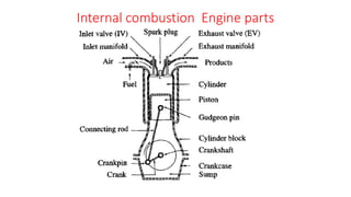
2. Cylinder block
• The cylinder block is the main supporting
structure for the various components.
• The cylinder of a multi cylinder engine
are cast as a single unit, called cylinder
block.
• The cylinder head is mounted on the
cylinder block.
• The cylinder head and cylinder block are
provided with water jackets in the case of
water cooling or with cooling fins in the
case of air cooling.
3. Cylinder
• As the name implies it is a
cylindrical vessel or space in which
the piston makes a reciprocating
motion.
• The varying volume created in the
cylinder during the operation of
the engine is filled with the
working fluid and subjected to
different thermodynamic
processes.
• The cylinder is supported in the
cylinder block.
4. Piston
• It is a cylindrical component fitted
into the cylinder forming the
moving boundary of the
combustion system.
• It fits perfectly (snugly) into the
cylinder providing a gas-tight
space with the piston rings and
the lubricant.
• It forms the first link in
transmitting the gas forces to the
output shaft.
5. Combustion chamber
• The space enclosed in the upper part of
the cylinder, by the cylinder head and the
piston top during the combustion
process, is called the combustion
chamber.
• The combustion of fuel and the
consequent release of thermal energy
results in the building up of pressure in
this part of the cylinder.
6. Inlet manifold
• The pipe which connects
the intake system to the
inlet valve of the engine
and through which air or
air-fuel mixture is drawn
into the cylinder is called
the inlet manifold.
7. Exhaust manifold
• The pipe which
connects the exhaust
system to the exhaust
valve of the engine
and through which
the products of
combustion escape
into the atmosphere
is called the exhaust
manifold.
8.
9. Inlet and Exhaust valves
• Valves are commonly
mushroom shaped pop-pet
type. They are provided
either on the cylinder head
or on the side of the cylinder
for regulating the charge
coming into the cylinder
(inlet valve) and for
discharging the products of
combustion (exhaust valve)
from the cylinder.
10. Spark Plug
• It is a component to
initiate the combustion
process in Spark- Ignition
(SI) engines and is usually
located on the cylinder
head.
11. Connecting Rod
• It interconnects the piston and
the crankshaft and transmits the
gas forces from the piston to the
crankshaft.
• The two ends of the connecting
rod are called as small end and
the big end.
• Small end is connected to the
piston by gudgeon pin and the
big end is connected to the
crankshaft by crankpin.
12. Crankshaft
• It converts the reciprocating motion of the piston into useful rotary motion of
the output shaft. In the crankshaft of a single cylinder engine there are a pair
of crank arms and balance weights.
• The balance weights are provided for static and dynamic balancing of the
rotating system.
• The crankshaft is enclosed in a crankcase.
13. Piston rings
• Piston rings, fitted
into the slots around
the piston, provide a
tight seal between
the piston and the
cylinder wall thus
preventing leakage
of combustion gases.
•Gudgeon pin
• It links the small end
of the connecting
rod and the piston.
14. Camshaft
• The camshaft (not shown in the
figure) and its associated parts
control the opening and closing of
the two valves.
• The associated parts are push
rods, rocker arms, valve springs
and tappets.
• This shaft also provides the drive
to the ignition system.
• The camshaft is driven by the
crankshaft through timing gears.
15. Cams
• These are made
as integral parts
of the camshaft
and are so de-
signed to open
the valves at the
correct timing
and to keep them
open for the
necessary
duration.
16. Flywheel
• The net torque imparted to the
crankshaft during one complete
cycle of operation of the engine
fluctuates causing a change in
the angular velocity of the shaft.
• In order to achieve a uniform
torque an inertia mass in the
form of a wheel is attached to
the output shaft and this wheel
is called the flywheel.