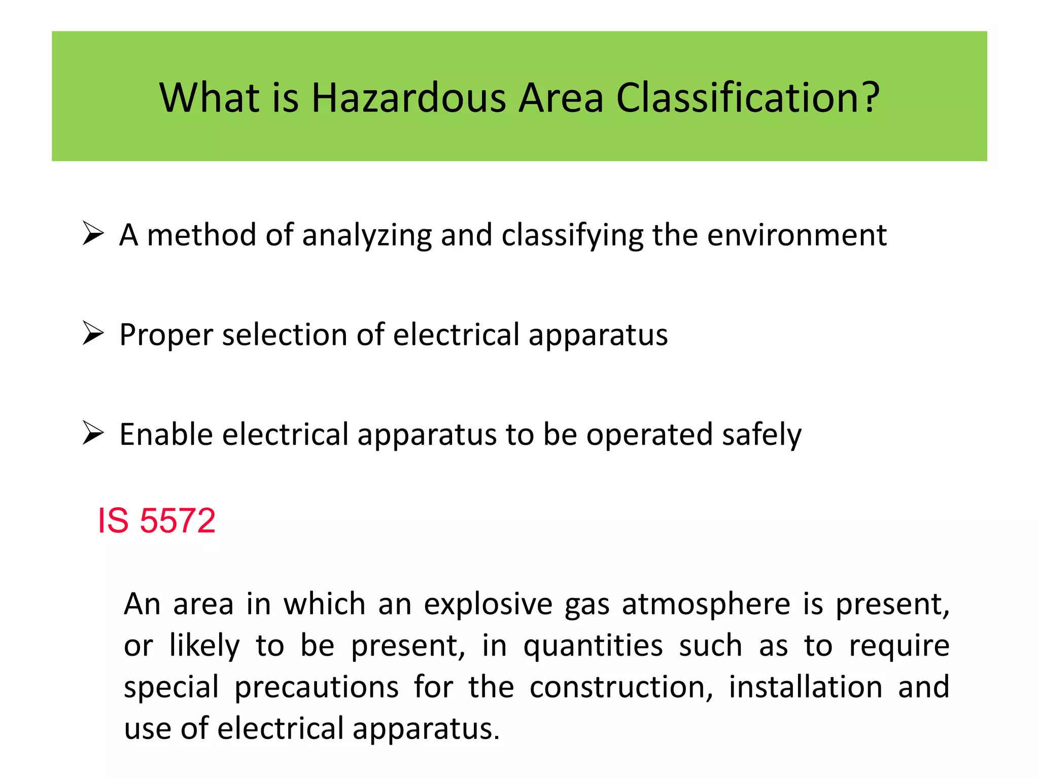
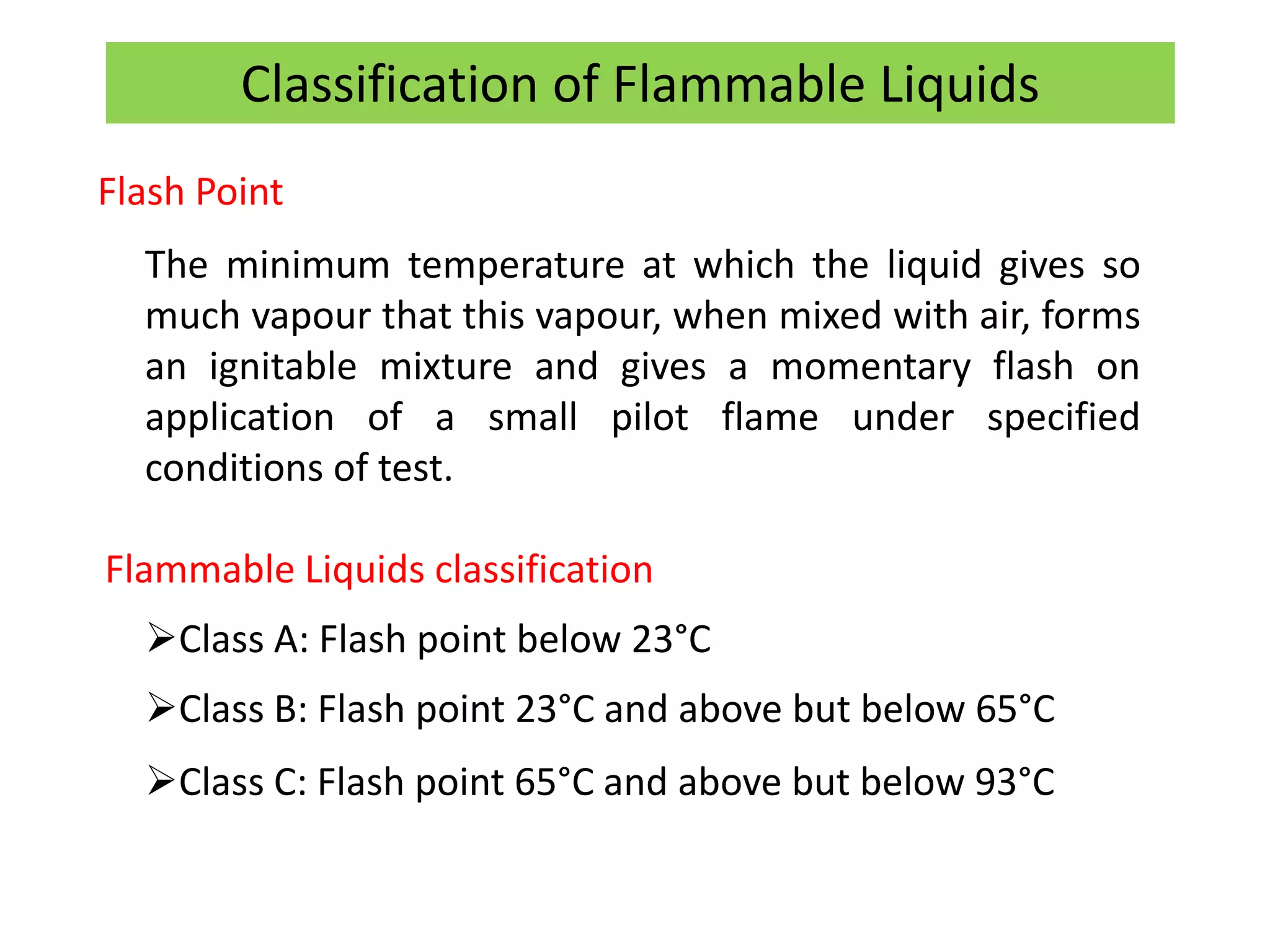
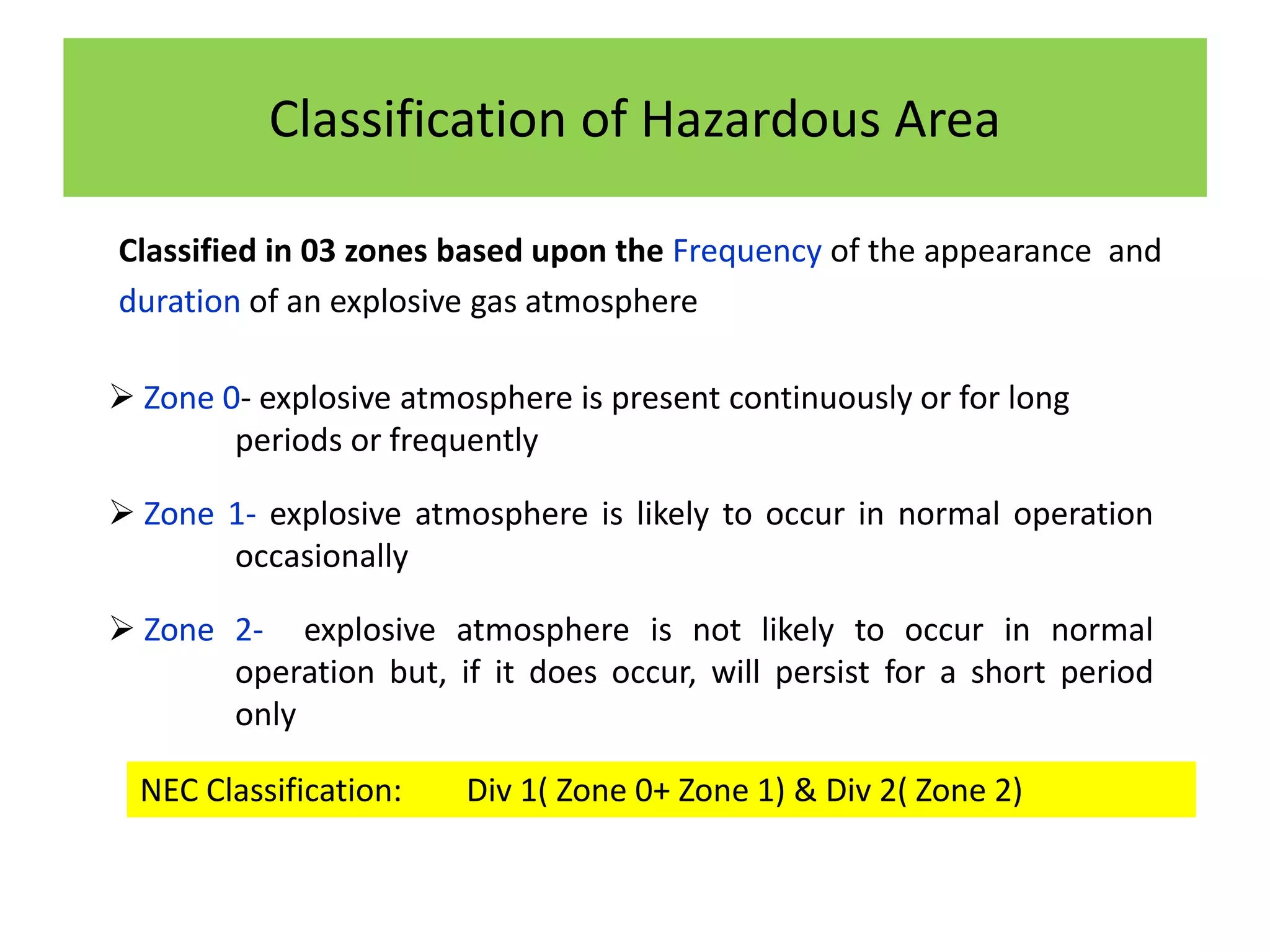
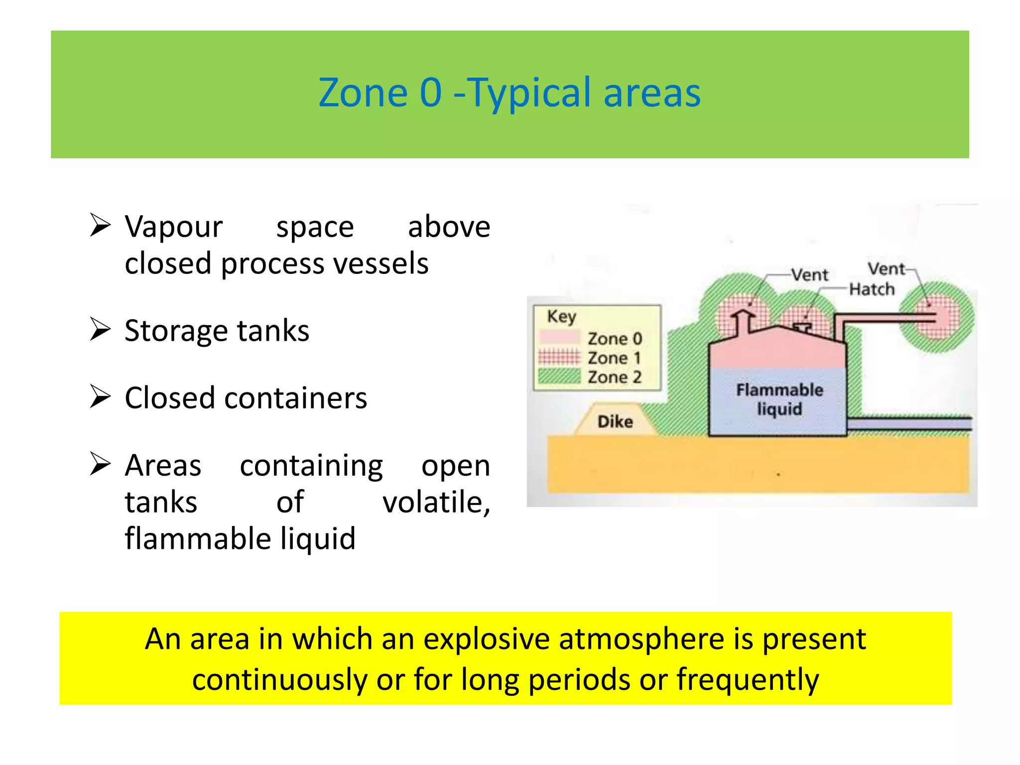
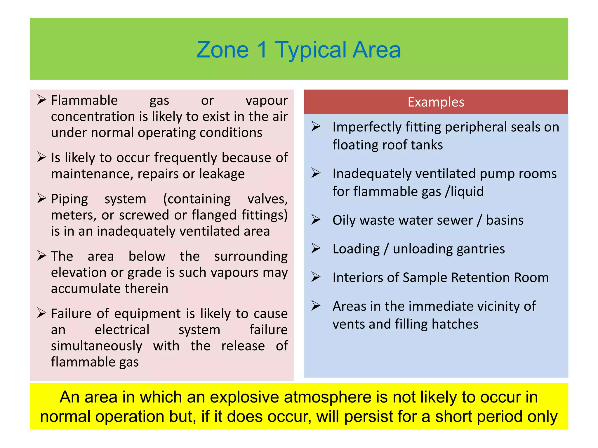
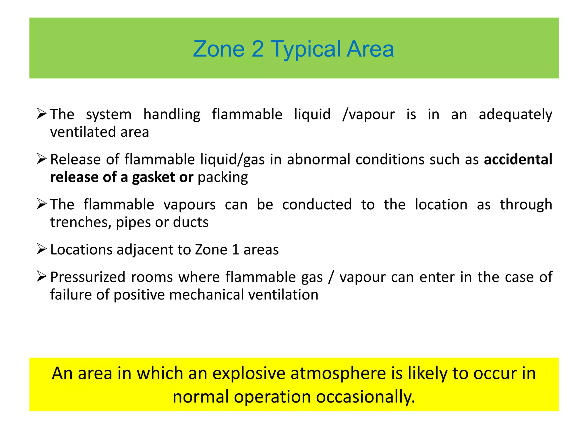
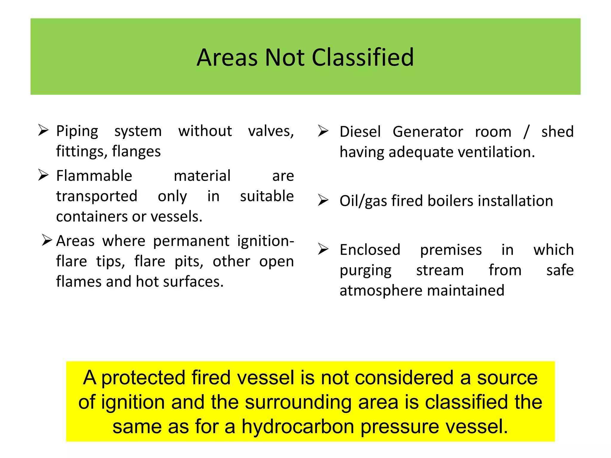
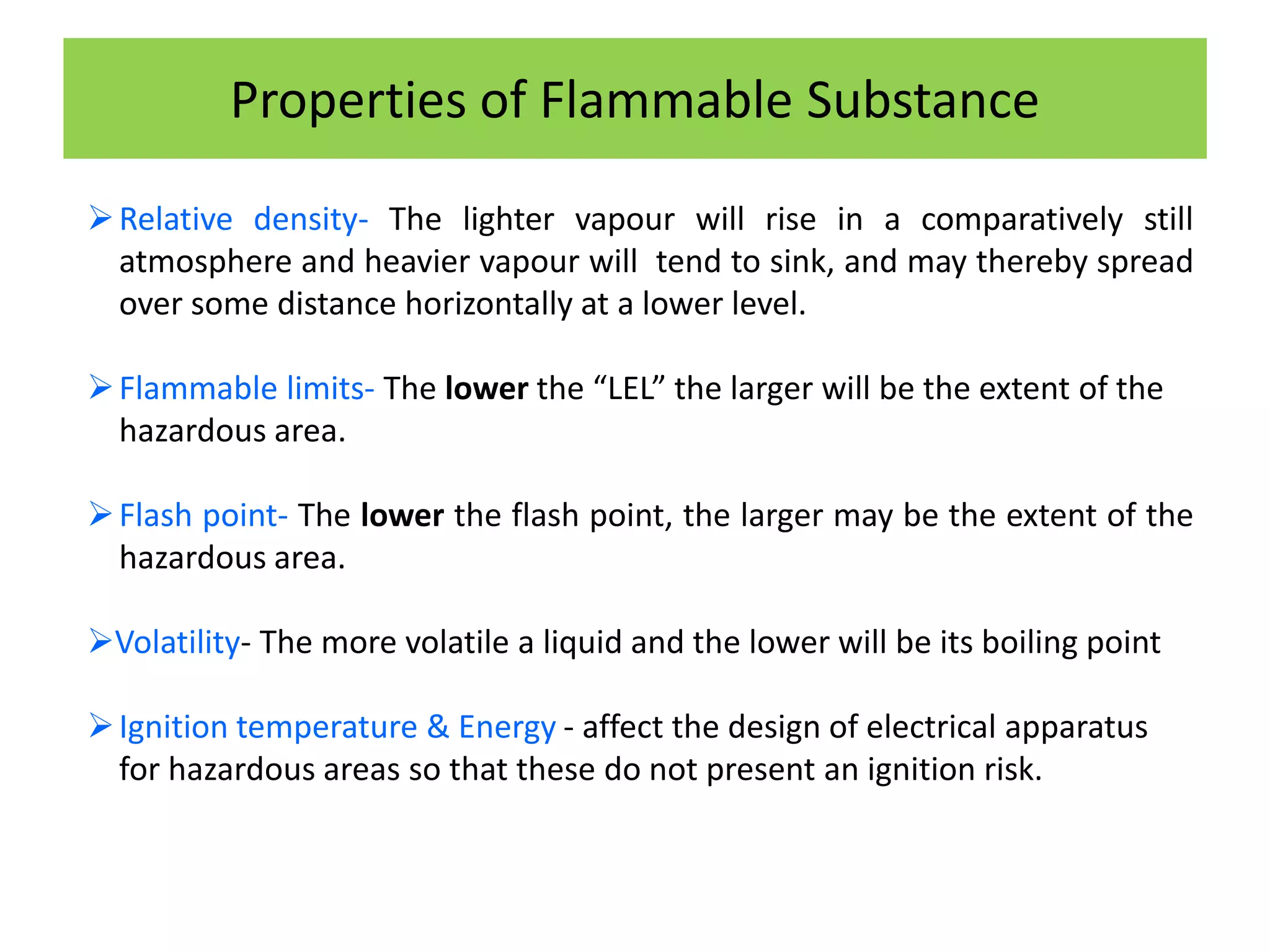
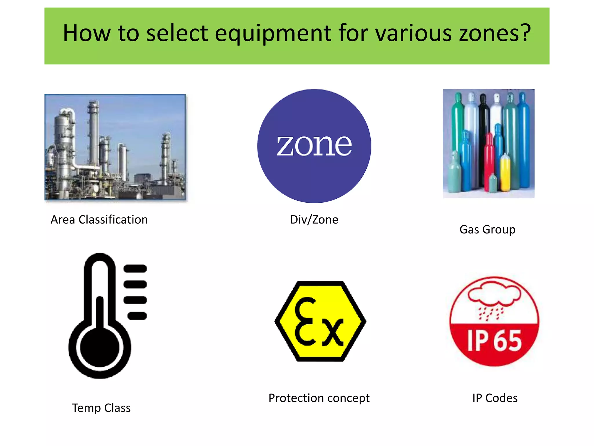
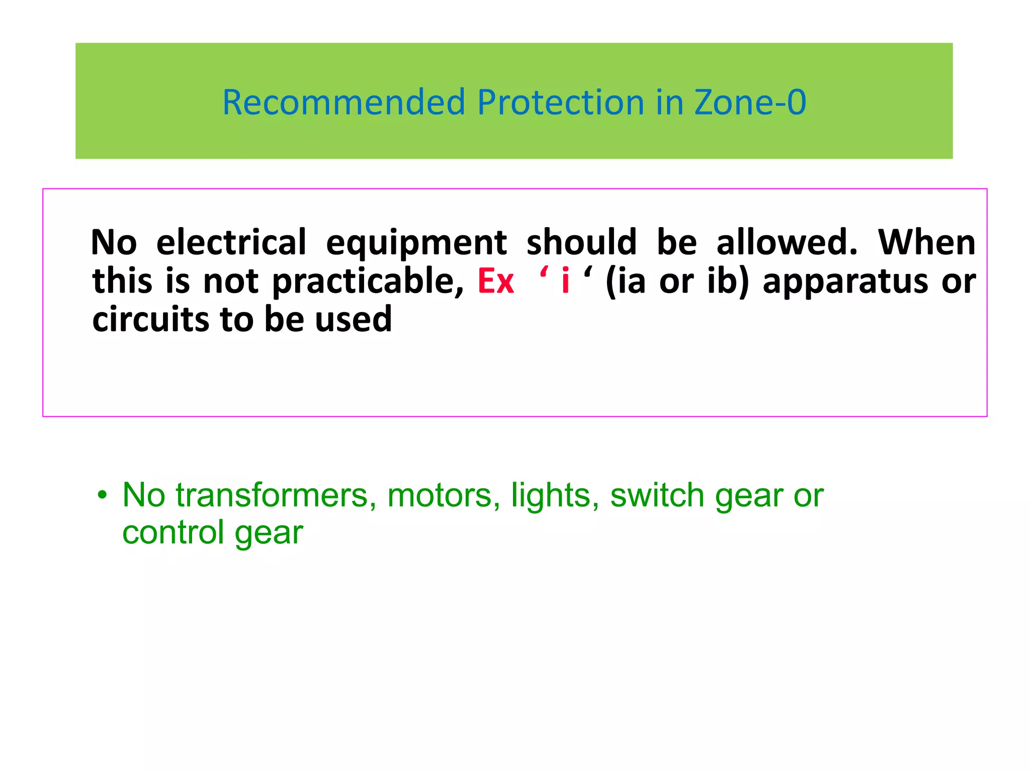
HAZARDOUS AREA CLASSIFICATION
Debabrata Das
Indian Oil Corporation Limited
Objective
1
Understand concept of
Hazardous area Classification
2
Understand the selection of
Equipments for Hazardous Area
Agenda
 Basic concept of Hazardous area
 Classification of Hazardous area
 Statutory requirements
 Selection of Equipments
Why Classify an Area as Hazardous?
Potential for explosion Safety of personnel Property Damage
Blast in a refinery due to non-classification of Cooling
Tower as Hazardous Area
What is Hazardous Area Classification?
 A method of analyzing and classifying the environment
 Proper selection of electrical apparatus
 Enable electrical apparatus to be operated safely
IS 5572
An area in which an explosive gas atmosphere is present,
or likely to be present, in quantities such as to require
special precautions for the construction, installation and
use of electrical apparatus.
Hazardous Areas-Definitions
Petroleum Rule 1976
An area shall be deemed to be a hazardous area, where
(i) Petroleum liquid having flash point below 65°C or any
flammable gas or vapour in a concentration capable of
ignition is likely to be present.
(ii) Petroleum or any flammable liquid having flash point
above 65°C is likely to be refined, blended, handled or
stored at or above its flash point.
Flash Point
The minimum temperature at which the liquid gives so
much vapour that this vapour, when mixed with air, forms
an ignitable mixture and gives a momentary flash on
application of a small pilot flame under specified
conditions of test.
Flammable Liquids classification
Class A: Flash point below 23°C
Class B: Flash point 23°C and above but below 65°C
Class C: Flash point 65°C and above but below 93°C
Classification of Flammable Liquids
Explosive Limit
 Lower Explosive Limit (LEL) – below which an explosive gas
atmosphere will not be formed.
 Upper Explosive Limit (UEL) –above which an explosive gas
atmosphere will not be formed.
Explosive Atmosphere
Explosive Gas Atmosphere
 A mixture with air of flammable materials
 In the form of gas, vapour, or mist
 After ignition, combustion spreads throughout the mixture
Measured with Explosive Meter at out Locations
Agenda
 Basic concept of Hazardous area
 Classification of Hazardous area
 Statutory requirements
 Selection of Equipments
Classification of Hazardous Area
Class I
Typical Environment
• Oil Refinery
• Terminal
• Bottling Plant
Class II
Typical Environment
• Coal Mine
• Grain Silo
• Hay Storage
Areas where flammable
gaes/vapours may be
present
Areas where
combustible dust be
may present
Class III
Areas where
combustible dust be
may present
Typical Environment
• Textile Mill
• Paper Mill
• Wook factory
Classification of Hazardous Area
 Zone 0- explosive atmosphere is present continuously or for long
periods or frequently
 Zone 1- explosive atmosphere is likely to occur in normal operation
occasionally
 Zone 2- explosive atmosphere is not likely to occur in normal
operation but, if it does occur, will persist for a short period
only
Classified in 03 zones based upon the Frequency of the appearance and
duration of an explosive gas atmosphere
NEC Classification: Div 1( Zone 0+ Zone 1) & Div 2( Zone 2)
Zone 0 -Typical areas
 Vapour space above
closed process vessels
 Storage tanks
 Closed containers
 Areas containing open
tanks of volatile,
flammable liquid
An area in which an explosive atmosphere is present
continuously or for long periods or frequently
Zone 1 Typical Area
 Flammable gas or vapour
concentration is likely to exist in the air
under normal operating conditions
 Is likely to occur frequently because of
maintenance, repairs or leakage
 Piping system (containing valves,
meters, or screwed or flanged fittings)
is in an inadequately ventilated area
 The area below the surrounding
elevation or grade is such vapours may
accumulate therein
 Failure of equipment is likely to cause
an electrical system failure
simultaneously with the release of
flammable gas
 Imperfectly fitting peripheral seals on
floating roof tanks
 Inadequately ventilated pump rooms
for flammable gas /liquid
 Oily waste water sewer / basins
 Loading / unloading gantries
 Interiors of Sample Retention Room
 Areas in the immediate vicinity of
vents and filling hatches
An area in which an explosive atmosphere is not likely to occur in
normal operation but, if it does occur, will persist for a short period only
Examples
Zone 2 Typical Area
The system handling flammable liquid /vapour is in an adequately
ventilated area
Release of flammable liquid/gas in abnormal conditions such as accidental
release of a gasket or packing
The flammable vapours can be conducted to the location as through
trenches, pipes or ducts
Locations adjacent to Zone 1 areas
Pressurized rooms where flammable gas / vapour can enter in the case of
failure of positive mechanical ventilation
An area in which an explosive atmosphere is likely to occur in
normal operation occasionally.
Areas Not Classified
 Piping system without valves,
fittings, flanges
 Flammable material are
transported only in suitable
containers or vessels.
Areas where permanent ignition-
flare tips, flare pits, other open
flames and hot surfaces.
 Diesel Generator room / shed
having adequate ventilation.
 Oil/gas fired boilers installation
 Enclosed premises in which
purging stream from safe
atmosphere maintained
A protected fired vessel is not considered a source
of ignition and the surrounding area is classified the
same as for a hydrocarbon pressure vessel.
Properties of Flammable Substance
Relative density- The lighter vapour will rise in a comparatively still
atmosphere and heavier vapour will tend to sink, and may thereby spread
over some distance horizontally at a lower level.
Flammable limits- The lower the “LEL” the larger will be the extent of the
hazardous area.
Flash point- The lower the flash point, the larger may be the extent of the
hazardous area.
Volatility- The more volatile a liquid and the lower will be its boiling point
Ignition temperature & Energy - affect the design of electrical apparatus
for hazardous areas so that these do not present an ignition risk.
Factors Affecting Extent of Hazard
•Increasing temperature
of process liquid
•The lower the IBP
results in greater
concentration of vapour
at the release source
•Rate of release of
flammable material
Temp Air
•A very mild breeze may
serve to extend the area
in those directions to
which vapours might
normally be carried.
•A stronger breeze may
so accelerate the
dispersion of vapours
that the extent of
potentially hazardous
area would be greatly
reduced.
Ventilation
•Increased rate of
ventilation, the extent of
hazardous area may be
reduced
•Obstacles e.g. dykes,
walls may impede the
ventilation and thus may
enlarge the extent.
• On the other hand,
they may limit the
movement of a cloud of
an explosive gas
atmosphere and thus
may reduce the extent.
Elevated or depressed sources of release will alter the areas of potential hazards.
Grouping Of Industrial Gas
Categorized into Group-I and Group-II gases(IS-9570)
Group-I : Found in the coal mining
industry(Methane)
Group-II: Subgroups in the increasing order of
their explosiveness.
 Group-IIA: Acetone, ammonia, ethyl
alcohol, gasoline, LGP/ Propane.
 Group-IIB: Ethylene, acetaldehyde.
Group-IIC: Acetylene, hydrogen
To classify a flammable gas or vapour by its ability to get ignited by a hot
surface.
The temperature class defines the maximum surface temperature an electrical
apparatus is allowed to operate at.
The maximum surface temperature of the apparatus must always be lower than
the ignition temperature of the surrounding gases.
Apparatus, that are certified suitable for use in a hazardous area, should be
marked with their temperature class.
Temperature Class
Temperature Class Max Surface Temperature of
Apparatus in C
Ignition Temperature of the
Flammable Substance in C
T1 450 >450
T2 300 >300<=450
T3 200 >200<=300
T4 135 >135<=200
T5 100 >100<=135
T6 85 >85<=100
Gas group-Ignition Energy
GAS GROUP REPRESENATATIVE GAS IGNITION ENERGY
(mj)
I METHANE 280
II A PROPANE 260
II B ETHYLENE 95
II C HYDROGEN 18
VARIOUS GASES/VAPOURS (IS 13408 Part I)
Flammable limitS No Name of the
chemical
Minimum
Ignition
Current
(MIC) mA
Flash point
Deg. Cen.
Iignition
temperatur
e
(Deg C)
LEL UEL
1 Methane I,
T1
85 - 595 5% 15%
2 Ammonia
II A T1
- - 630 105 mg/l 200 mg/l
3 Ethylene
II B T2
45 - 425 2.7% 34%
4 Propane
II A T1
70 - 470 2% 9.5%
5 Acetylene
II C T2
24 - 305 1.5 % 100%
Case-1
Case-2
Case-3
Case-4
Case-5
Case-6
Case-7
Case-8
Case-9
Agenda
 Basic concept of Hazardous area
 Classification of Hazardous area
 Regulations, Guidelines
 Selection of Equipments
Various Standards
Certifying Agencies
Factory Mutual Underwriters Laboratories
CMRI
Dhanbad
Statutory Regulations
• Petroleum Act, 1884
– Petroleum Rules, 1976
• Explosive Act, 1934
– Explosive Rules, 1983
– Gas Cylinder Rules, 1981
– Static & Mobile pressure Vessel (Unfired) Rules, 1981
CCoE, Department of Explosives is entrusted with the
responsibility of administration of the above statutory rules
in India
Agenda
 Basic concept of Hazardous area
 Classification of Hazardous area
 Statutory requirements
 Selection of Equipments
How to select equipment for various zones?
Area Classification Div/Zone
Gas Group
Temp Class
Protection concept IP Codes
FLAMMABLE
MIXTURE, EXPLOSION
Protection concepts
 No Arcs, sparks, or hot surface-
Increased Safety, Non-incendive
 Containing the explosion and extinguishing the flame-
Explosion proof, flame proof, power filled
 Limiting energy – Intrinsically Safe
Keeping Flammable material Out
Pressurized, encapsulated, oil emersion,
Type of Protection
Type Ex-
Code
Description Location Use
Flameproof d A method of protection where the
enclosure of apparatus will
withstand an internal explosion of
the inflammable gas which may
enter it without causing damage
and without communicating the
internal inflammation to the
external flammable gas. he escaping
(hot) gases must sufficiently cool
down along the escape path that by
the time they reach the outside of
the enclosure not to be a source of
ignition of the outside, potentially
ignitable surroundings.
Zone 1 if gas
group &
temp. class
correct
Motors,
lighting,
junction
boxes,
electronics
Type of Protection
Type Ex-
Code
Description Location Use
Intrinsically
safe
i A protection technique based upon
based on restriction of electrical
energy within apparatus and in the
interconnecting wiring, exposed to
potentially explosive atmosphere, to
a level below that which can cause
ignition by either sparking or
heating effects. Because of the
method by which intrinsic safety is
achieved it is necessary that not
only the electrical apparatus
exposed to the potentially explosive
atmosphere but also other electrical
apparatus with which it is
interconnected is suitably
constructed
'ia‘ : Zone 0
'ib‘: Zone1
'ic : Zone 2
Instrumentation,
measurement,
control
Type of Protection
Type Ex-
Code
Description Location Use
Pressurized/
purged
p Equipment is pressurized to a
positive pressure relative to the
surrounding atmosphere with air or
an inert gas, thus the surrounding
ignitable atmosphere can not come
in contact with energized parts of
the apparatus. The overpressure is
monitored, maintained and
controlled.
Zone 1 (px
or py), or
zone 2 (pz)
Analyzers,
motors, control
boxes,
computers
Oil
immersed
o A method of protection where
electrical apparatus is made safe by
oil immersion in the sense that
flammable gasses or vapors above
the oil or outside the enclosure will
not be ignited
Zone 2 or
Zone 1
switchgear
Type of Protection
Non
Incendive
n A type of protection applied to an
electrical apparatus such that in
normal operation, it is not capable
of igniting a surrounding explosive
atmosphere, and a fault capable of
causing ignition is not likely to occur
Zone 2
Motors, lighting,
junction boxes,
electronic
equipment
Special
Protection
s A concept for those type of
electrical apparatus that, by their
nature do not comply with the
constructional or other
requirements specified for
apparatus with established types of
protection, but which nevertheless
can be shown, where necessary by
test, to be suitable for use in
hazardous areas in prescribed zones
Zone
depending
upon
Manufactur
ers
Certificatio
n.
As its
certification
states
Type of Protection
Increased
Safety
e A method of protection by which
additional measures are applied to
an electrical apparatus to give
increased security against the
possibility of excessive
temperatures and of the
occurrences of arcs and sparks
during service life of the apparatus.
It applies only to an electrical
apparatus, no part of which produce
arcs or sparks or exceed the limiting
temperature in normal service
Zone 2 or
Zone 1
Motors, lighting,
junction boxes
Sand filled q A method of protection where the
enclosure of the electrical apparatus
is filled with a mass of powdery
material such that, if an arc occurs,
the arc will not be liable to ignite
the outer flammable atmosphere
Zone 2 or
Zone 1
Electronics,
telephones,
chokes
IP Types and Protection Details
FIRST NUMERAL
0 No protection
1 Objects greater than 50 mm
2 Objects greater than 12 mm
3 Objects greater than 2.5 mm
4 Objects greater than 1.0 mm
5 Dust - protected
6 Dust tight
SECOND NUMERAL
0 No protection
1 Vertically dripping
2 Angular dripping
3 Sprayed water
4 Splashed water
5 Water jets
6 Heavy seas
7 Effects of immersion
8 Indefinite immersion
IP XY
Degree of Solid ingress Ingress of Liquid
Recommended Protection in Zone-0
No electrical equipment should be allowed. When
this is not practicable, Ex ‘ i ‘ (ia or ib) apparatus or
circuits to be used
• No transformers, motors, lights, switch gear or
control gear
Recommended Protection in Zone-1
Motors- Ex d, Ex p
Transformers & Capacitors - Ex d
Control & Instrument Transformers - Ex i
Lighting Fitting - Ex d
Switch Gear & Control Gear - Ex d
Communication/ Telephone equipment/Meters - Ex i
Portable Hand Lamps- Ex i
*Ex o, Ex q type equipment are also allowed for use
as per IS 5571
Recommended Protection in Zone-2
Motors- Ex d, Ex p, Ex n, Ex e,
Transformers & Capacitors - Ex d, Ex p (auxiliary devices to be
located in pressurized room/hermetically sealed /
intrinsically safe)
Control & Instrument Transformers - Ex i
Lighting Fitting - Ex d, Ex e, Ex n
Switch Gear & Control Gear - Ex d, Ex o, Ex
Communication/ Telephone equipment/Meters - Ex i
Portable Hand Lamps- Ex i
* Minimum IP 55 (for UN-insulated parts) and IP 44 (for
insulated parts) if Ex e protection is used for outdoor
applications
Hazardous Area Classification

Hazardous Area Classification

  • 1.
    HAZARDOUS AREA CLASSIFICATION DebabrataDas Indian Oil Corporation Limited
  • 2.
    Objective 1 Understand concept of Hazardousarea Classification 2 Understand the selection of Equipments for Hazardous Area
  • 3.
    Agenda  Basic conceptof Hazardous area  Classification of Hazardous area  Statutory requirements  Selection of Equipments
  • 4.
    Why Classify anArea as Hazardous? Potential for explosion Safety of personnel Property Damage Blast in a refinery due to non-classification of Cooling Tower as Hazardous Area
  • 5.
    What is HazardousArea Classification?  A method of analyzing and classifying the environment  Proper selection of electrical apparatus  Enable electrical apparatus to be operated safely IS 5572 An area in which an explosive gas atmosphere is present, or likely to be present, in quantities such as to require special precautions for the construction, installation and use of electrical apparatus.
  • 6.
    Hazardous Areas-Definitions Petroleum Rule1976 An area shall be deemed to be a hazardous area, where (i) Petroleum liquid having flash point below 65°C or any flammable gas or vapour in a concentration capable of ignition is likely to be present. (ii) Petroleum or any flammable liquid having flash point above 65°C is likely to be refined, blended, handled or stored at or above its flash point.
  • 7.
    Flash Point The minimumtemperature at which the liquid gives so much vapour that this vapour, when mixed with air, forms an ignitable mixture and gives a momentary flash on application of a small pilot flame under specified conditions of test. Flammable Liquids classification Class A: Flash point below 23°C Class B: Flash point 23°C and above but below 65°C Class C: Flash point 65°C and above but below 93°C Classification of Flammable Liquids
  • 8.
    Explosive Limit  LowerExplosive Limit (LEL) – below which an explosive gas atmosphere will not be formed.  Upper Explosive Limit (UEL) –above which an explosive gas atmosphere will not be formed. Explosive Atmosphere Explosive Gas Atmosphere  A mixture with air of flammable materials  In the form of gas, vapour, or mist  After ignition, combustion spreads throughout the mixture Measured with Explosive Meter at out Locations
  • 9.
    Agenda  Basic conceptof Hazardous area  Classification of Hazardous area  Statutory requirements  Selection of Equipments
  • 10.
    Classification of HazardousArea Class I Typical Environment • Oil Refinery • Terminal • Bottling Plant Class II Typical Environment • Coal Mine • Grain Silo • Hay Storage Areas where flammable gaes/vapours may be present Areas where combustible dust be may present Class III Areas where combustible dust be may present Typical Environment • Textile Mill • Paper Mill • Wook factory
  • 11.
    Classification of HazardousArea  Zone 0- explosive atmosphere is present continuously or for long periods or frequently  Zone 1- explosive atmosphere is likely to occur in normal operation occasionally  Zone 2- explosive atmosphere is not likely to occur in normal operation but, if it does occur, will persist for a short period only Classified in 03 zones based upon the Frequency of the appearance and duration of an explosive gas atmosphere NEC Classification: Div 1( Zone 0+ Zone 1) & Div 2( Zone 2)
  • 12.
    Zone 0 -Typicalareas  Vapour space above closed process vessels  Storage tanks  Closed containers  Areas containing open tanks of volatile, flammable liquid An area in which an explosive atmosphere is present continuously or for long periods or frequently
  • 13.
    Zone 1 TypicalArea  Flammable gas or vapour concentration is likely to exist in the air under normal operating conditions  Is likely to occur frequently because of maintenance, repairs or leakage  Piping system (containing valves, meters, or screwed or flanged fittings) is in an inadequately ventilated area  The area below the surrounding elevation or grade is such vapours may accumulate therein  Failure of equipment is likely to cause an electrical system failure simultaneously with the release of flammable gas  Imperfectly fitting peripheral seals on floating roof tanks  Inadequately ventilated pump rooms for flammable gas /liquid  Oily waste water sewer / basins  Loading / unloading gantries  Interiors of Sample Retention Room  Areas in the immediate vicinity of vents and filling hatches An area in which an explosive atmosphere is not likely to occur in normal operation but, if it does occur, will persist for a short period only Examples
  • 14.
    Zone 2 TypicalArea The system handling flammable liquid /vapour is in an adequately ventilated area Release of flammable liquid/gas in abnormal conditions such as accidental release of a gasket or packing The flammable vapours can be conducted to the location as through trenches, pipes or ducts Locations adjacent to Zone 1 areas Pressurized rooms where flammable gas / vapour can enter in the case of failure of positive mechanical ventilation An area in which an explosive atmosphere is likely to occur in normal operation occasionally.
  • 15.
    Areas Not Classified Piping system without valves, fittings, flanges  Flammable material are transported only in suitable containers or vessels. Areas where permanent ignition- flare tips, flare pits, other open flames and hot surfaces.  Diesel Generator room / shed having adequate ventilation.  Oil/gas fired boilers installation  Enclosed premises in which purging stream from safe atmosphere maintained A protected fired vessel is not considered a source of ignition and the surrounding area is classified the same as for a hydrocarbon pressure vessel.
  • 16.
    Properties of FlammableSubstance Relative density- The lighter vapour will rise in a comparatively still atmosphere and heavier vapour will tend to sink, and may thereby spread over some distance horizontally at a lower level. Flammable limits- The lower the “LEL” the larger will be the extent of the hazardous area. Flash point- The lower the flash point, the larger may be the extent of the hazardous area. Volatility- The more volatile a liquid and the lower will be its boiling point Ignition temperature & Energy - affect the design of electrical apparatus for hazardous areas so that these do not present an ignition risk.
  • 17.
    Factors Affecting Extentof Hazard •Increasing temperature of process liquid •The lower the IBP results in greater concentration of vapour at the release source •Rate of release of flammable material Temp Air •A very mild breeze may serve to extend the area in those directions to which vapours might normally be carried. •A stronger breeze may so accelerate the dispersion of vapours that the extent of potentially hazardous area would be greatly reduced. Ventilation •Increased rate of ventilation, the extent of hazardous area may be reduced •Obstacles e.g. dykes, walls may impede the ventilation and thus may enlarge the extent. • On the other hand, they may limit the movement of a cloud of an explosive gas atmosphere and thus may reduce the extent. Elevated or depressed sources of release will alter the areas of potential hazards.
  • 18.
    Grouping Of IndustrialGas Categorized into Group-I and Group-II gases(IS-9570) Group-I : Found in the coal mining industry(Methane) Group-II: Subgroups in the increasing order of their explosiveness.  Group-IIA: Acetone, ammonia, ethyl alcohol, gasoline, LGP/ Propane.  Group-IIB: Ethylene, acetaldehyde. Group-IIC: Acetylene, hydrogen
  • 19.
    To classify aflammable gas or vapour by its ability to get ignited by a hot surface. The temperature class defines the maximum surface temperature an electrical apparatus is allowed to operate at. The maximum surface temperature of the apparatus must always be lower than the ignition temperature of the surrounding gases. Apparatus, that are certified suitable for use in a hazardous area, should be marked with their temperature class. Temperature Class Temperature Class Max Surface Temperature of Apparatus in C Ignition Temperature of the Flammable Substance in C T1 450 >450 T2 300 >300<=450 T3 200 >200<=300 T4 135 >135<=200 T5 100 >100<=135 T6 85 >85<=100
  • 20.
    Gas group-Ignition Energy GASGROUP REPRESENATATIVE GAS IGNITION ENERGY (mj) I METHANE 280 II A PROPANE 260 II B ETHYLENE 95 II C HYDROGEN 18
  • 21.
    VARIOUS GASES/VAPOURS (IS13408 Part I) Flammable limitS No Name of the chemical Minimum Ignition Current (MIC) mA Flash point Deg. Cen. Iignition temperatur e (Deg C) LEL UEL 1 Methane I, T1 85 - 595 5% 15% 2 Ammonia II A T1 - - 630 105 mg/l 200 mg/l 3 Ethylene II B T2 45 - 425 2.7% 34% 4 Propane II A T1 70 - 470 2% 9.5% 5 Acetylene II C T2 24 - 305 1.5 % 100%
  • 22.
  • 23.
  • 24.
  • 25.
  • 26.
  • 27.
  • 28.
  • 29.
  • 30.
  • 31.
    Agenda  Basic conceptof Hazardous area  Classification of Hazardous area  Regulations, Guidelines  Selection of Equipments
  • 32.
  • 33.
    Certifying Agencies Factory MutualUnderwriters Laboratories CMRI Dhanbad
  • 34.
    Statutory Regulations • PetroleumAct, 1884 – Petroleum Rules, 1976 • Explosive Act, 1934 – Explosive Rules, 1983 – Gas Cylinder Rules, 1981 – Static & Mobile pressure Vessel (Unfired) Rules, 1981 CCoE, Department of Explosives is entrusted with the responsibility of administration of the above statutory rules in India
  • 35.
    Agenda  Basic conceptof Hazardous area  Classification of Hazardous area  Statutory requirements  Selection of Equipments
  • 36.
    How to selectequipment for various zones? Area Classification Div/Zone Gas Group Temp Class Protection concept IP Codes
  • 37.
  • 38.
    Protection concepts  NoArcs, sparks, or hot surface- Increased Safety, Non-incendive  Containing the explosion and extinguishing the flame- Explosion proof, flame proof, power filled  Limiting energy – Intrinsically Safe Keeping Flammable material Out Pressurized, encapsulated, oil emersion,
  • 39.
    Type of Protection TypeEx- Code Description Location Use Flameproof d A method of protection where the enclosure of apparatus will withstand an internal explosion of the inflammable gas which may enter it without causing damage and without communicating the internal inflammation to the external flammable gas. he escaping (hot) gases must sufficiently cool down along the escape path that by the time they reach the outside of the enclosure not to be a source of ignition of the outside, potentially ignitable surroundings. Zone 1 if gas group & temp. class correct Motors, lighting, junction boxes, electronics
  • 40.
    Type of Protection TypeEx- Code Description Location Use Intrinsically safe i A protection technique based upon based on restriction of electrical energy within apparatus and in the interconnecting wiring, exposed to potentially explosive atmosphere, to a level below that which can cause ignition by either sparking or heating effects. Because of the method by which intrinsic safety is achieved it is necessary that not only the electrical apparatus exposed to the potentially explosive atmosphere but also other electrical apparatus with which it is interconnected is suitably constructed 'ia‘ : Zone 0 'ib‘: Zone1 'ic : Zone 2 Instrumentation, measurement, control
  • 41.
    Type of Protection TypeEx- Code Description Location Use Pressurized/ purged p Equipment is pressurized to a positive pressure relative to the surrounding atmosphere with air or an inert gas, thus the surrounding ignitable atmosphere can not come in contact with energized parts of the apparatus. The overpressure is monitored, maintained and controlled. Zone 1 (px or py), or zone 2 (pz) Analyzers, motors, control boxes, computers Oil immersed o A method of protection where electrical apparatus is made safe by oil immersion in the sense that flammable gasses or vapors above the oil or outside the enclosure will not be ignited Zone 2 or Zone 1 switchgear
  • 42.
    Type of Protection Non Incendive nA type of protection applied to an electrical apparatus such that in normal operation, it is not capable of igniting a surrounding explosive atmosphere, and a fault capable of causing ignition is not likely to occur Zone 2 Motors, lighting, junction boxes, electronic equipment Special Protection s A concept for those type of electrical apparatus that, by their nature do not comply with the constructional or other requirements specified for apparatus with established types of protection, but which nevertheless can be shown, where necessary by test, to be suitable for use in hazardous areas in prescribed zones Zone depending upon Manufactur ers Certificatio n. As its certification states
  • 43.
    Type of Protection Increased Safety eA method of protection by which additional measures are applied to an electrical apparatus to give increased security against the possibility of excessive temperatures and of the occurrences of arcs and sparks during service life of the apparatus. It applies only to an electrical apparatus, no part of which produce arcs or sparks or exceed the limiting temperature in normal service Zone 2 or Zone 1 Motors, lighting, junction boxes Sand filled q A method of protection where the enclosure of the electrical apparatus is filled with a mass of powdery material such that, if an arc occurs, the arc will not be liable to ignite the outer flammable atmosphere Zone 2 or Zone 1 Electronics, telephones, chokes
  • 44.
    IP Types andProtection Details FIRST NUMERAL 0 No protection 1 Objects greater than 50 mm 2 Objects greater than 12 mm 3 Objects greater than 2.5 mm 4 Objects greater than 1.0 mm 5 Dust - protected 6 Dust tight SECOND NUMERAL 0 No protection 1 Vertically dripping 2 Angular dripping 3 Sprayed water 4 Splashed water 5 Water jets 6 Heavy seas 7 Effects of immersion 8 Indefinite immersion IP XY Degree of Solid ingress Ingress of Liquid
  • 45.
    Recommended Protection inZone-0 No electrical equipment should be allowed. When this is not practicable, Ex ‘ i ‘ (ia or ib) apparatus or circuits to be used • No transformers, motors, lights, switch gear or control gear
  • 46.
    Recommended Protection inZone-1 Motors- Ex d, Ex p Transformers & Capacitors - Ex d Control & Instrument Transformers - Ex i Lighting Fitting - Ex d Switch Gear & Control Gear - Ex d Communication/ Telephone equipment/Meters - Ex i Portable Hand Lamps- Ex i *Ex o, Ex q type equipment are also allowed for use as per IS 5571
  • 47.
    Recommended Protection inZone-2 Motors- Ex d, Ex p, Ex n, Ex e, Transformers & Capacitors - Ex d, Ex p (auxiliary devices to be located in pressurized room/hermetically sealed / intrinsically safe) Control & Instrument Transformers - Ex i Lighting Fitting - Ex d, Ex e, Ex n Switch Gear & Control Gear - Ex d, Ex o, Ex Communication/ Telephone equipment/Meters - Ex i Portable Hand Lamps- Ex i * Minimum IP 55 (for UN-insulated parts) and IP 44 (for insulated parts) if Ex e protection is used for outdoor applications